

Page 1
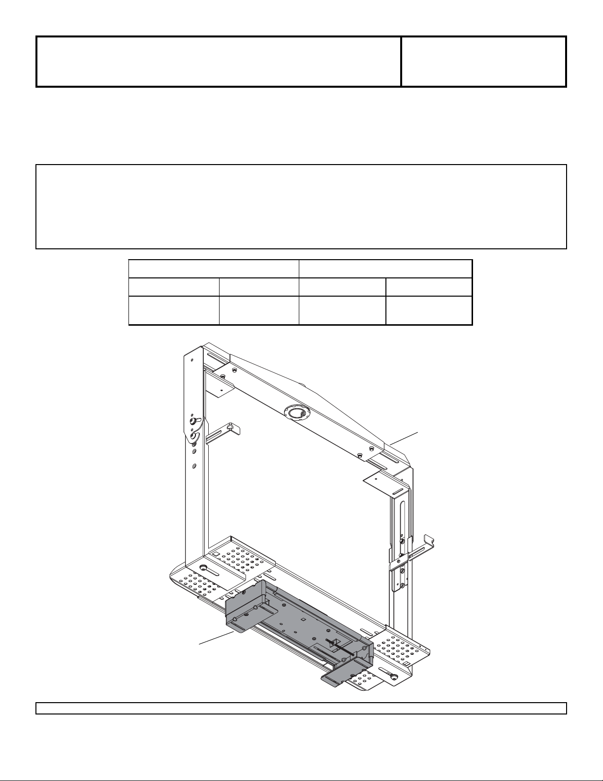
Installation and Assembly -
)
DVD/DVR/VCR Mount for
Jumbo® Mount
Models: VPM 25-J, VPM 25-JS,
SVPM 25-J, SVPM 25-JS
Maximum Load Capacity:
50 lb (22.7 kg)
Read instruction sheet before you start installation and assembly.
Installing a DVD/DVR/VCR Mount to a Jumbo® Mount with Threaded Holes in Center of Tr a y .................... page 3
Installing a DVD/DVR/VCR Mount to a Jumbo Mount with Slots in Center of Tray ........................................ page 3
Installing a Single DVD/DVR/VCR Mount........................................................................................................... page 4
Installing Multiple DVD/DVR/VCR Mounts.......................................................................................................... page 5
INSI D E DI M ENS IO NS MEDI A PL AYER DIMENS I O NS
W IDT H (W) HEIGHT (H) MAXI MUM MI NIM UM
13.25" - 17. 25" 1.5" - 2.75" 17.25" x 2. 50" 13.25" x 1. 5"
(337 mm - 438 mm) (38 mm - 70 mm ) (438 mm x 64 mm ) (337 mm x 38 mm
DVD/DVR/VCR MOUNT
Visit the Peerless Web Site at www.peerlessindustries.com
1 of 5
JUMBO MOUNT
ISSUED: 05-19-04 SHEET #: 081-9032-3 02-14-06
For customer service call 1-800-729-0307 or 708-865-8870.
Page 2
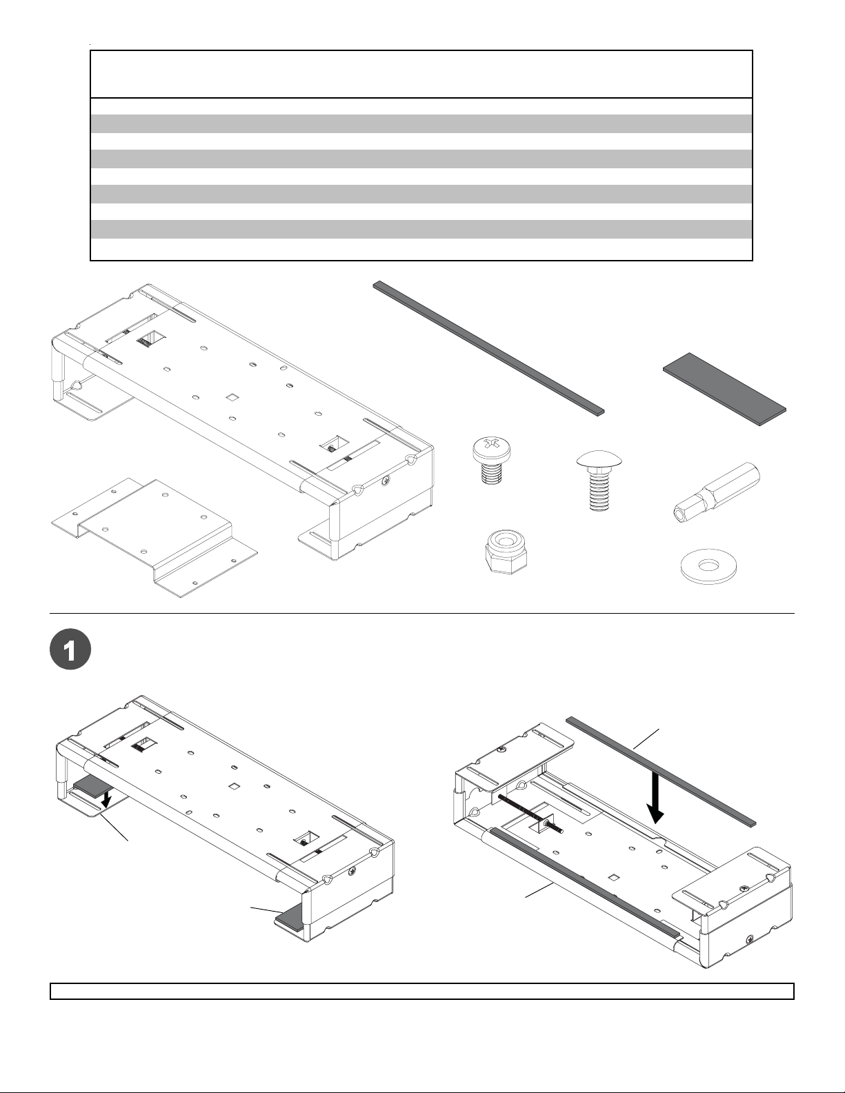
Parts Li st
Description Qty. Part Part Part Part
DVD/DVR/DVR mount 1 081-0072 081-0076 081-0073 081-0077
A
hanger bracket 1 1255-275 081-4086 1255-275 081-4086
B
M5 x . 8 x 8 mm s el f-tapping phil l i ps sc rew 8 520-1167 520-2167 520-1167 520-2167
C
#10-24 x 1/2" carriage bolt 8 520-9523 520-2104 520-9523 520-2104
D
#10-24 nyloc k nut 8 530-9341 530-9342 530-9341 530-9342
E
#10 SAE washer 8 540-9400 540-9442 540-9400 540-9442
F
M5 x 1" pent a-pin™ t ool driver 1 – – 520-9249 520-9249
G
1.5" x 4. 5" x .125" adhes i ve foam 2 599-1122 599-1122 599-1122 599-1122
H
.375" x 12. 75" x . 125" adhes i ve foam 2 599-3802 599-3802 599-3802 599-3802
I
VPM 25-J VPM 25-JS SVPM 25-J SVPM 25-JS
A
I
H
C
B
D
E
G
F
Peel and place four pieces of adhesive foam (H, I) on the horizontal cross support and vertical adjusters as shown
in figure 1.1 and 1.2.
I
VERTICAL ADJUSTER
H
fig 1.1
Visit the Peerless Web Site at www.peerlessindustries.com
2 of 5
HORIZONTAL
CROSS
SUPPORT
fig 1.2
ISSUED: 05-19-04 SHEET #: 081-9032-3 02-14-06
For customer service call 1-800-729-0307 or 708-865-8870.
Page 3

Installing a DVD/DVR/VCR Mount to a Jumbo® Mount with Threaded Holes in
Center of Tray
Attach hanger bracket (B) underneath the Jumbo mount using four M5 x 8 mm screws (C) as in shown figure 2.1.
Attach DVD/DVR/VCR mount (A) to hanger bracket (B) using four M5 x 8 mm screws (C) as in shown figure 2.2.
CUTA WA Y VIEW OF JUMBO MOUNT
TRAY
THREADED HOLES
CUTA WA Y VIEW OF JUMBO MOUNT
B
B
fig 2.1
C
fig 2.2
Installing a DVD/DVR/VCR Mount to a Jumbo Mount with Slots in Center of Tray
Attach hanger bracket (B) underneath the Jumbo mount using four #10-24 carriage bolts (D), #10 SAE washers
(F), and #10-24 nylock nuts (E) as shown in figure 3.1. Att ach DVD/DVR/VCR mount (A) to hanger bracket (B)
using M5 x 8 mm screws (C) as shown in figure 3.2.
C
CUTA WA Y VIEW OF JUMBO MOUNT
D
TRAY
SLOTS
B
F
fig 3.1 fig 3.2
E
3 of 5
Visit the Peerless Web Site at www.peerlessindustries.com
CUTA WA Y VIEW OF JUMBO MOUNT
B
A
C
ISSUED: 05-19-04 SHEET #: 081-9032-3 02-14-06
For customer service call 1-800-729-0307 or 708-865-8870.
Page 4

Installing a Single DVD/DVR/VCR Mount
Adjust size of DVD/DVR/VCR mount (A) to fit media player by loosening vertical and horizontal adjustment screws
where shown in figure 4.1 on both sides. Insert media player and align front of player with front of TV on Jumbo
mount. Tighten vertical and horizontal adjustment screws where shown in figure 4.2 on both sides until player
securely fits in mount.
Note: TV and Jumbo mount not shown in illustrations.
HORIZONTAL ADJUSTMENT SCREW
fig 4.1
A
MEDIA PLA YER
VERTICAL ADJUSTMENT SCREW
A
HORIZONTAL ADJUSTMENT SCREW
VERTICAL ADJUSTMENT SCREW
fig 4.2
Visit the Peerless Web Site at www.peerlessindustries.com
4 of 5
ISSUED: 05-19-04 SHEET #: 081-9032-3 02-14-06
For customer service call 1-800-729-0307 or 708-865-8870.
Page 5

Installing Multiple DVD/DVR/VCR Mounts
If adhesive foam (H) is covering slots, trim foam (H) to expose slots. Insert four carriage bolts (D) into
slots of upper DVD mount (A). Loosely attach lower DVD mount (A) using four #10 SAE washers (F)
and #10-24 nylock nuts (E). This will allow access to the vertical adjustment screws of the upper mount
by being able to easily move the lower mount. Note: TV and TV mount not shown in illustrations.
WARNING
• Do not stack more than three DVD/DVR/VCR Mounts
from a TV mount.
WARNING
• St acked load cannot exceed 50 lb.
VERTICAL
ADJUSTMENT
SCREW
LOWER MOUNT (A)
UPPER MOUNT (A)
H
Adjust size of the upper DVD mount (A) to fit media player by loosening screws on both sides. Insert
media player and align front of player with front of TV on TV mount. Tighten vertical and horizontal
adjustment screws where shown on both sides until player securely fits in mount.
Note: To access the vertical adjustment screws of the upper mount, slide the lower mount to the side.
Repeat for the opposite side.
Center lower DVD mount (A) and securely tighten four nuts (E). Repeat beginning of this step to install
the media player into the lower DVD mount.
D
F
E
DETAIL 1
MEDIA PLA YER
LOWER MOUNT
Visit the Peerless Web Site at www.peerlessindustries.com
© 2004 Peerless Industries, Inc. All rights reserved.
Peerless and Jumbo are registered trademarks and Penta-Pin is a trademark of Peerless Industries, Inc.
All other brand and product names are trademarks or registered trademarks of their respective owners.
5 of 5
HORIZONTAL ADJUSTMENT
UPPER MOUNT
VERTICAL ADJUSTMENT
ISSUED: 05-19-04 SHEET #: 081-9032-3 02-14-06
For customer service call 1-800-729-0307 or 708-865-8870.
 Loading...