

PEERLESS SERIES TC, TC-04, TC-05, TC-06, TC-07 Installation, Operation & Maintenance Manual
...Page 1
TC
Gas/Off Boilers
Installation,
Operation
Maintenance
Manual
pr=-r=-I_Lr=-SS®
CAST IRON BOILERS
Page 2

15 Sizes
Oil, Gas or Combination Gas]Oil Fired,
Hot Water or Steam Boilers
4-18 Sections 8.0 to 40.5 GPH Input 900 to 4,629 MBH Gross Output
Rugged Cast-Iron, Wet Base Sections
• Dzlrabl_ _ Corks m_ lOlLJot Loag L!fe and Optunllm I error mam:e
• CaT_ Be Asselrg)led al Job Siie
Forced Draft Venting
• Only RequirPs a Throe Foot Vent Above the Roo./
High Efficiency Power Burners
• Choice o.fBeckelt, Carlia, Power Flame, Webster. Gordon Piatt
• Provide the tf_hesi Possible E.{fi('iencies
Front and Rear Flame Observation Ports
• Aid Burner Selup
Oval-Shaped Upper Port
• Improves IT_teraal Circulation
• [-felps Creale Dr_j Sleam
Hi-Temperature, Flexible, Graphite Port Connectors
• Simplifij l_stallalion
• [Jl_q_2cled by Chemicals
Side Cleanout Access
• Assures Easy Cleaning oflqueways
Integral Cast Iron Flue Collector
• Adds Durability
• Reduces OperaliJ_g Noise
Tankless Coils
• For Domestic Hot Water on Sleam and Hot Waler Boilers
Insulated Enameled Steel Jacket
• Reduce_ Boiler Heat Loss
Short, Individual Draw Rods
• Simplify Assembly
• Reduce Slmss
• Burner Mortaring Plate with lllsulation Block
• 30 PSIASME Saj'e__ Relie]-Valve (Water Boilers)
• 15 PSI ASME Side Outlet Safe_. Valve (Steam Boilers)
• LWCO on Packaged Boilers
• Wide Variety of Tcmkless Heater Options
• Assembled Seclior'Ls
• Combixlation Low-Water CutoJ]aad Water F_'edel
P('i'l'lt_._;s Boils'Is is plc'ci_,_'(l Io _1]€'! olt(' _)] IIl_' nlo_;I ('olllplx,ll(,ltsit_<, w(u'roltty prof4rams ill Ih<" ill(lll._lUi. All P_'t_r[t!._;s col!lll!_'lx'i(ll
<'tlNl il'olt I)oil('15 ilte.'[tlcl(' _ ]illl, oil(' y<'ar It)(ll'l'(llll{]. A limit_,(l, lell yt'tu" ivanzulty oil Ill(" Ctl.g[ i!OII _('clioIl:q I.'q i_tovid_'d lbr _I1 corn
Ilr'l_'irl! I101 II_(ll('l (1!_(1 _;I¢'_llll t)oil_'t_. Fil_" (_ll(J I(!ll_!j('(lr (,xle_ded tValT(lltli_s oil pal_s (lilcJ I(lt)or (llx' llOII1 al,(lilable. PIt,(l.s_" ('(it_
s_l!l P_'_'l!_'s_; I$oil_'l% [})I _ olllplt'lt" II_(II_TUlI!I il!fi_llll(lliOII.
Peerless Boilers • www.peerless-heater.com
Page 3

Peerless Heater Company presents...
Series TO
Forced Draft Commercial Oil, Gas or
Combination Gas/Oil Boilers
The Series TCcast iron boiler can be used in either
hol water or steam systems. The oii, _.asor combination
_.as/oil-fired boiler is available in 15sizes and is ideal for
lar_.ecommerclal applications. The Series TCboiler is
designed with forced draft firin_ to provide the highest
possible efficiencies. The boiler's _ross output ratings
range from 900 to 4,629 MBH.
Series TC boilers are constructed of ru_,ed, cast-iron,
wet-base sections with cast-in heat extraction pins that
assure durability and top performance. Hi-temperature,
flexible, _raphite port connectors, and short, individual
draw rods simpli_ installation. Front and rear flame
observation ports aid burner setup.
All Series TCboilers are available with a slandard, built-in
cast iron flue collector with integral damper and a burner
mountin_ plate with insulation block. Steel an_.le floor rails
and ceramic fiber rope seal between seclions are also
standard. Series TC boilers feature 80 psi workin_ pressure
sections. A 30 psi ASMEsafety relief valve is standard on
water boilers. Steam boilers include a t5 psi ASME side
outlet safety valve and steam _au_e All Series TCboilers
are equipped with an insulated enameled sleel jacket.
Peerless Series TC boilers are available with your
choice of Becketl, Carlin, Power Flame, Gordon Piatt or
Webster burners.
PEERLESS
CAST IRON BOILERS
The Preferred Heatiz_ Choice
Page 4

Series TO Features
• Power Burners - Oil. Gas, Gas/Oil
• Steam or Hot Water Boilers
• Ru_ed. Oast-lronConstruction
• Forced Draft Venting
• Wet-Base Sections
• Oast-in Heat ExtractionPins
• IntegralOast Iron Flue Oollector
• Hi-Temperature. Flexible,Graphite Port Connectors
Orderin_ Information:
Example:
O- TC- - W-ST - 30 PSI
| Series | 15 PSI Steam (STD)
| | 30 PSI Water (STD)
Blank = NO Burner 50 PSI Water
O = Oil li gO PSI Water
G - Gas WATER STEAM
GO - Gas/Oil W S = Less Burner
WL SL Less Burner & Controls
WU SU W/gurneT & Controls
WUP SUP = PkO.. w/Burner & Controls
WP SP Pkg. Less Burner
WLP SLP = PR#.. Less Burner & Controls
Series TC Standard Equipment
• Insulated Enameled Steel Jacket
• CastIron Flue Collector with Integral Damper
• Bumer Mounting Plate with Insulation Block
• Front and Rear Flame Observation Ports
• Steel Angle Floor Rails
• Ceramic Fiber Rope Seal Between Sections
• Manual Reset, Limit Control
• Operatin_ Control
Water
• 80 PSIWorking Pressure, CastIron Sections
• 30 PSIASMESafety Relief Valve
• Temperature Pressure Gauge
• Return Yoke with Flexible Seals
Steam
• 15 PSIASMESide Outlet Safety Valve
• Steam Gauge
• Gau_e Glasswith Gauge Cocks and Guards
Series TC Optional Equipment
• Combination Low Water Cutoffand Feeder
• Tankless Heater Sections
:. tankless Heaters
• Assembled Seaions
• Packaged Boilers
Inspection Tappin_s, 1-1/2". 3 per Section
Return Yoke (Steam)
Barometric Damper
Burner Specifications
Boiler
Model
Nuh,ber
re04
TC 05
TC-06
T( 07
rC 08
TC 09
TC I0
T( II
TC 12
r( I ]
IC 14
T( 15
T( Ib
l( 17
IL 18
Beckelt
Model
(:rl l0 T
O1 10_
LF2 )O 1
CF2 )O:
CF2 )0 _
(F2 )0 2
Cf2 )0 _
CH! OA:
CI3! 0A2|
i
Burners - Light Oii
Carlin
Model
NO. H.R
Gordon Plait Power Hame Webster
Mode_ Model Mode_
NO. H.P. NO H P. NO. H.P.
R8"GO _ H C1 01 & JBI0-03 I
R8 2-GO _ !g C1 0' 5 ]B10-0] _ 91_
B8 2-GO L E2 DA z 4 )BIB-B71 Va
R8 2 GOI k_ C2-OA 1 'a JBI0 072 :_/_
R84 GO _ 2 C20B _ I JB10072 :_/_
R84GO I 2 20131: _, ]g20-1O 1
RIB.I GO z 2 L2"DBll / JB2_tB 2
RIOIGO l 3 (101 2 JB20-10 l
RIO I GO t 3 C] "O° 2 ]B20 202
RlO I-GO t ] (30 _ 2 1B20-20 _
RIB2GO _ 5 [3"0 _ 2 JB20213 _
R102GO/ 5 (_0B l ] ]B20 30l
RIO2GO: 5 (3.0B; ] JB20]O
RI0 -)(]O t 5 (40A 2 5 JB30-]0 t
RI_2(,D ! 5 (4{/A 3 I )_303Bl
I
Gordon Plait
Model
NO. HP.
R8G _ _
R82 O t _4
RB 2 G r %
R82 G 1 _4
R84(fl
R84 G 1
R_B 1 G_
R101 G _
RIO 1 Gl
RIO I-G z
R_B2 G_
R)02 {/
R102 G _
RIO 2 G'
RI_T 2 G"
Burners - Gas
Power Flame
Mode_
No H.P.
J30-X 12r
JSO_ 15_
)SO_,19
J5OA-15I
C2 G 20_,2
C2G 20B1;
C2-G 2{)gl
C3 G 20 _
L] G 25 _
C3-G 25
f3%2_:
C3.G.258 _
C] G 251{ !
(4 (, 25
£4 G 25 z
Webste_
Model
NO. H.P
IBIG O] _ V{
IBIG O] _ V_
)BIG O5t V_
IBIG-O5 _ ,/z
IB1G 05 _ Y_
]B2G-IO _ I
JB2G 10 _ 1
JB2G 10_ 1
]B2G 152 I12
JB2G.152 I]/
}B2G 15_ Ib'
JB2G-30 _ 3
JB2G 30 _ 3
JB2G 301 3
]B2G 3B _
Gordon Plait
Mod'_
NO. 4.P
R801 '/_
R8201 ¼
Rt_ 201 Y4
R8.2-O 1
Rfl4-O _
R84 O;
Rlr_I.O z
R101 O _
R10t O z
RI0 i.O _
R1B 2 O:
R102-O:
RIO 20 z
RI 02 O _
Rlg 2() ¸' %
Burners - Gas/Oil
Power Flame Webster
Model Model
NO. -l.P. NO. H,P.
C1-G0-12 _ [_z JBTC4)3 _ /a
C1 G0-I2 _ /2 JBICO3 _ /a
C2-GB-IS _ Y_ |BI£433 _ A
C2 GO 1S_ _/4 J81C_7 z _/_
C2_30 2OA _ l JBIC4)7 _ V_
Z2-GO-2OBI 1 9_z JB2C-101
24_B 2B_]12 % 1B2£ tO _
C3-GO-2O: 2 J82C-10 _
C3G025 _ 2 ]B2C 20 _
C3 GO 25_ 2 JB2C-20I
( 3-G($-251 2 IB2C 20_
(3G0258 _ 3 J82C-]0 _
C3-GO-25B _ 3 JB2(302
C4-GO 25: 5 JB3G301
C4 GO 252 5 IB3q 3B]
I [ttlln_ I opeldliorl: on-ol[
2 Burn(i opt'[alion: Io_-bre Marl, hi_h-bre run
Burn{'r ilpelaIiorl: full mildulalion
Nolu: IIl_ _. lliP.h II>_; or ModulaliOl] lilin_ (onsuk Pt'erle_,', H('dR'I Company
"ti>ur PeI'rlP'¢_ lh_aler Cl)mpanv represi'nlati_i' should b(' (onsullod before sele(tin_ boiB't', for inslallillion ha_ in_ unusudl pipin£_ and pick UD reQuiremenls, su(h d'_ in[ermiBenl
s\stem I)pefaIion, exlensive piDin _ svslems {'[{ I ol lorl ed hl)l _'.alcr healinQ s_slems where lhe boilel and all the pipinQ are within lhe area I(i b_' healed, the boiler may be
_,elot Iixl on [hi! basis ol ils Gross Oulpul
Page 5
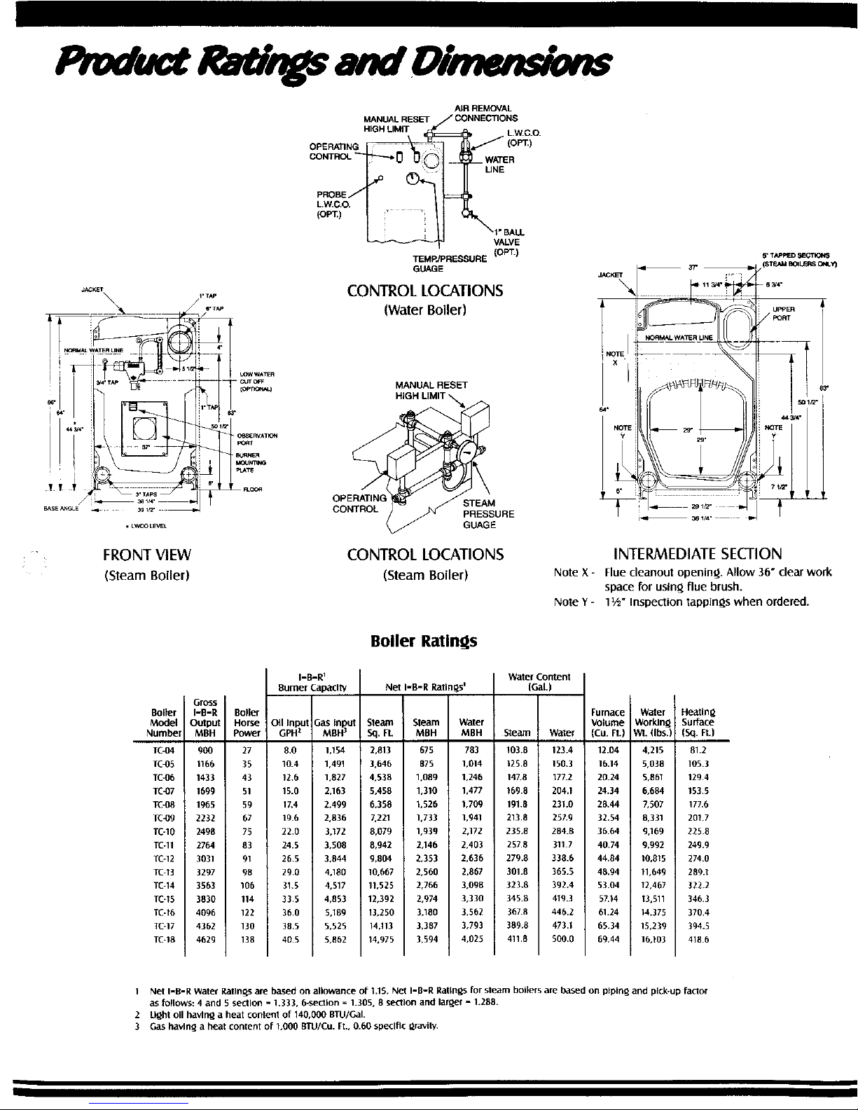
• FRONT VIEW
(Steam Boiler)
MANUALRESET
H]GH LIMIT
OPERATING
AIR REMOVAL
/CONNECTIONS
UNE
1"BALL
VALVE
TEMP./PRESSURE (OPT.)
GUAGE
CONTROL LOCATIONS
(Water Boiler)
MANUALRESET
OPERATING STEAM
CONTROL PRESSURE
GUAGE
CONTROL LOCATIONS
(Steam Boiler)
JAC_
\
5' TAPFEO_=CTIOI_
64"
NOTE
INTERMEDIATE SECTION
Note X- Flue cleanout opening. Allow 36" clearwork
spacefor using flue brush.
Note Y- 1½" Inspection tappings when ordered.
Boiler
Model
Number
TC_)4
TC-05
TC4)6
TC-07
TC_8
Tc_g
TC-10
TC-11
TC-12
TC-13
TC-14
TC-15
TC-16
TC-17
TC-18
Gross
I-B-R
Output
MBH
9O0
1166
1433
1699
1965
2232
2498
2764
3031
3297
3503
3830
4096
4362
4629
I-B-R 1
Burner Capadty
loller [
!orse OII Input Gas Input
'ower GPH z MBH 3
27 8.0 1,154
35 10.4 1,491
43 12.0 1,827
51 15.0 2,163
59 1L4 2,499
67 19.6 2,836
75 22.0 3,172
83 24.5 3,508
91 26.5 3,844
98 29.0 4,180
106 81.5 4,517
114 33.5 4,853
122 36.0 5,189
130 38.5 5,525
138 40.5 5,862
Boiler Ratings
Net I-B-R Ratln@s=
5teaxn Steam Water
Sq. Ft. MBH MBH
2,013 675 783
3,646 875 1,014
4,538 1,089 1,246
5,458 1,310 1,477
6,358 1,526 1.709
7,221 1,733 1,941
8,079 1,939 2,172
8,942 2,146 2,403
9,804 2,353 2,636
10,667 2,560 2,867
11,525 2,766 3.098
12,392 2,974 3,330
13,250 3,180 3,562
14.113 3,387 3,793
14,975 3,594 4,025
Water Content
(Gal.)
Ream Water
103.8 123.4
125.8 150.3
14L8 177.2
169.8 204.1
lgl.8 231.0
213.8 257.9
235.8 284.8
257.8 311.7
279,8 338.6
301.8 365.5
323.8 392.4
345.8 419.3
367.8 440,2
389,8 473.1
411.8 500.0
Furnace
Volume
(Cu. Ft.)
12.04
16.14
20.24
24.34
28.44
32,54
36.64
4074
44.84
48.94
53.04
57,14
61.24
65.34
69.44
Water !
Worldng
VlI. fibs.)
4,215
5,038
5,861
8,684
L507
8,331
9.169
9,992
10,815
11,649
12,467
13,511
14,375
15,239
16,103
Heatln_
Surface
(Sq. Ft.)
81.2
105.3
129.4
153.5
177.6
201.7
225.8
249.9
274.0
289.1
322.2
346.3
370.4
394.5
418.6
1 Net I=B-R Water Ratingsare based on allowance of 1.15. Net I=B=R Ratings for steam boilers are based on ptpJn_iand plcbup factor
as follows: 4 and 5 section = 1.333, 6-section = 1.305, 8 section and lar_er = 1.208.
2 Light oll havln_ a heat content of 140,000 BTU/GaI.
3 Gas havln_Jabeat content of 1,000 BTU/Cu. R., 0.60 specific _ravit_
Page 6

RE_URN
yOKE
BURNER _X. ,
o II I I II o
r-
rTA_m _U_
.... _ ...... ..,_. ....... _. _ X_ •
l ! "
i _2" i j
SIDE VIEW
Note X- Flue cleanout opening. Allow 36" clear work
space for usin_ flue brush.
Note Y - t½" Inspection tappin_s when ordered.
Note Z - Tankless heater sections when ordered. Allow 36" clear space for
heater withdrawal.
Optional Assembled Section and
Packa_led Base
*'Caution: Add 6" to all vertlcal measurements
on 4 - 14 section boilers and 8" on 15 - 18
sectlons.
(oPT.)
/
• VENT
CONNECTIONS
- SUDE DAMPER
(_SERVATION
PORT
WATER R_RN
CONNECTION 5'
RETURN YOKE
WATER BOILE/_ Opa_y
4" RETURN TAPFING
{BOTH SIDES)
REAR VIEW
Boiler Dimensions
Boiler
Model
Number
TC-04
TC4)5
TC-06
TG07
TC4)8
TC-09
TC-10
TC-11
TC-12
TC-13
TC-14
TC-15
TC-16
TC-17
TC-18
Overall LenRth - "A"_
Power
dl Be Flame Webster
¼ I 71%" 66"%"
,¼ : 83%" 74%"
,_ 81 91%" 82%"
1/_ 8; 99%" 90%"
% g' I07%" 98%"
1_ IC 115%" 110%"
i_/ 11 128" 118%"
;9 1_ 137%" 126%"
19 13 145%" 154%"
IZ/ 153%" 142%"
);/ 161%" 150%"
169%" 158%"
177%" 166%"
191%" 183%"
199%" 191%"
Optional
Package(
Base
Dimenslo
91sA_"
104%"
112_A_"
120%"
128%_"
136%"
144_A_"
157%"
165z%_"
173_/_"
181_¾_"
189%"
197z%_"
211"
219¼e"
Furnace
Len&_h
23_A_"
31%d'
39_Ae_
47%e_
55%_"
63%e"
71SAd"
79%_"
87%e"
95%6"
111_/1e"
119_ze"
127%e"
135_Ao"
Boiler
Ler_h
33"
41"
49"
57"
65"
73"
81"
8g"
97"
105"
113"
121"
129"
137"
145"
5reamUpla_eLocatlonS _
"D ° "E" "F"
12%"
20%"
12%" 16"
12%" 24"
12%" 32"
12V_" 40"
20%" 40"
20%" 24" 24"
20V2" 24" 32"
20%" 32" 32"
20%" 32" 40"
20%" 40" 40"
20%" 48" 40"
20_" 48" 48"
20%" 56" 48"
Draft
Loss Ins.
W.C.
.24
.25
.26
.27
.28
.29
.30
.31
.33
.34
.35
.36
.37
.38
39
Firebox
Press.
Ins.
W.C.*
.34
.35
.36
.37
.38
.39
.40
.41
.43
.44
.45
.46
.47
.48
.49
Dial
Vent
Conn.
"G"
10"
10"
10_
12"
12"
14"
14"
14"
14"
14"
16"
16"
16"
18"
18"
Height
Vent
Conn.
57%"
57%"
57%"
56%"
56%"
55%"
55%"
55%"
55%"
55%"
54%"
54%"
54%"
54%"
54%"
I When unit Isassembled or packaged, add 6" 1o hei_hls for 4 - 14 see., 8" to heights for 15 - 18 sect.
2 Add 2-3/4" to secllons 17 and 18 for flue oullet adapten
*Based on 0.10 Ins. W.C. pressure al boiler outlet. If venl slzin_ results in a back pressure Qreater than 0.10 ins. W.C., consult Peerless Heater Compan%
3 Tllese measLwemen?s are approximate.
Page 7
CONNECt GRAVI)_"
RETURN OR PUMP
RETURN BELOW
WATER LINE AND
ABOVE LOWEST
PERMISSIBLE
WATER LINE
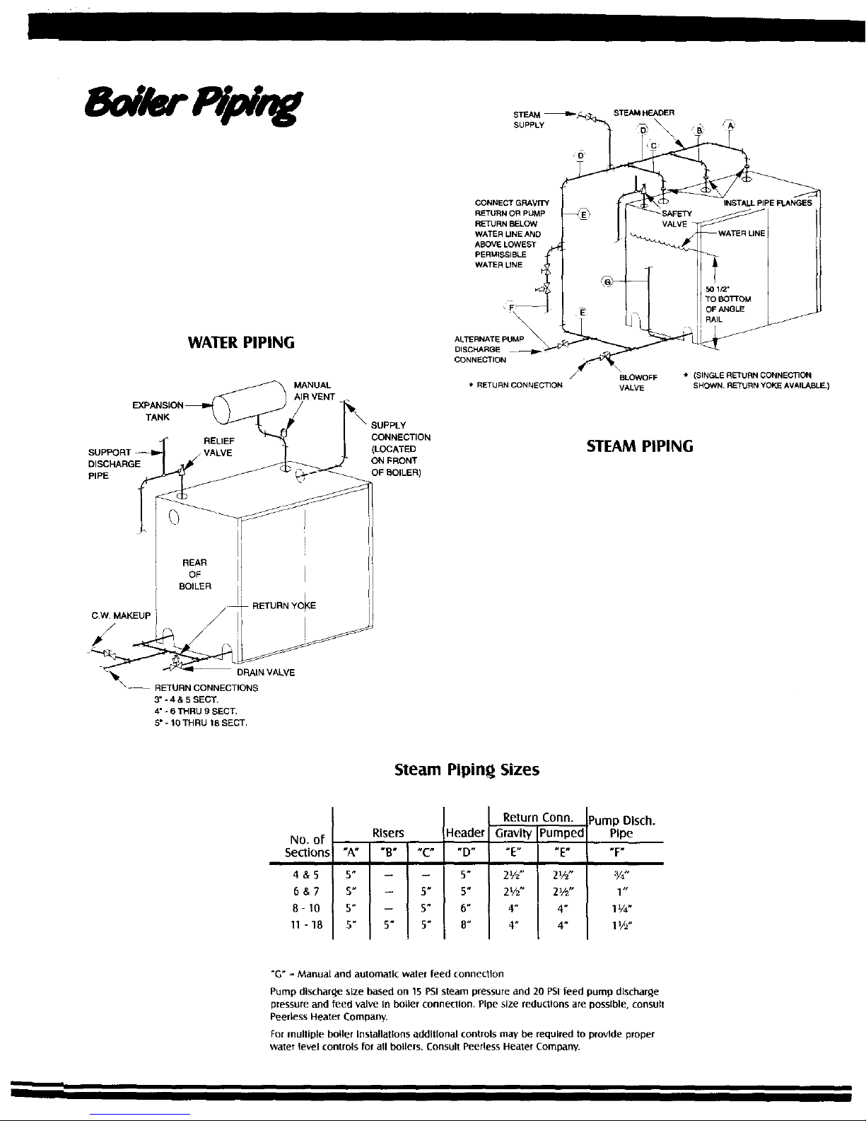
WATER PIPING
MANUAL
AIR VENT
EXPANSION _
TANK
RELIEF CONNECTION
SUPPORT _ VALVE (LOCATED
o,so ,RG ff ON RONT
PIPE OF ROLLER)
\
ALTERNATEPUMP_
DISCHARGE
CONNECTION
* RETURN CONNECTION
BLOWOFF * (SINGLE RETURN CONNECTION
VALVE SHOWN. RETURN YOKE AVAILABLE.)
STEAM PIPING
REAR
OF
BOILER
/
C.W. MAKEUP ' RETURN YO_E
vALVE
3" - 4 & 5 SECT.
4' - 6 THRU 9 SECT.
E" - t0 THRU 18 SECT,
Steam Plpin_ Sizes
No. of
Sections
4&S
o&7
8- 10
11 -18
Risers
.A.I.8.l.c.
5" -- J --
5" -- I 5"
S" -- S"
5" 5" 5"
Header
"D"
s"
5"
6"
8"
Return
Gravity
2V2"
2%"
4"
4"
Conn.
_umped
_E R
21/2"
2_"
4"
4"
•ump Dlsch.
Pipe
I"
1¼"
1½"
"G" = Manual and automatic water feed connection
Pump dischar_e size based on 15 PSI steam pressure and 20 PSI feed pump discharge
pressure and feed valve In boller connection. Pipe size reductions are DOSslble, consult
Peerless Heater Company.
For multiple boiler Installatlons additional controls may be required to provide proper
water level controls for all bo_lers. Consult Peerless Heater Compan_
Page 8

No. of
Sections
4 Section
5 Section
6 Section
7 Section
8 Section
9 Section
10 Section
II Section
12 Section
13 Section
14 Section
15 Section
16 Section
17 Section
18 Section
Arrangement of
Sections for Steam Boilers
F-T-H-B
F-H-T-H-B
F-T-H-T-H-B
F-T-H-P-T-H-B
F-T-H-P-H-T-H-B
F-T-H-P-H-P-T-H-B
F-H-T-H-P-H-P-T-H-B
F-H-T-H-P-ToH-P-T-H-B
F-H-T-H-P-T-H-P-H-T-H-B
F-H-T-H-P-H-T-H-P_H-T-H-B
F-H-T-H-P-H-T-H-P-H-P-T-H-B
F-H-T-H-P-H-P-T-H-P-H-P-T-H-B
F-H-T-H-P-H-P-H-T-H-P-H-P-T-H-B
F-H-T-H-P-H-P-H-T-H-P-H-P-H-T-H-B
F-H-T-H-P-H-P-H-PoT-H-P-H-P-H-T-H-B
F = Front Section
T = Intermediate Sectlon with 5" Tapping
H = Optlonal Intermediate Heater SeCtion
P = Plain Intermediate Sectlon
B = Back
Boiler
Model
Number
SM8-TC
SM12-TC
Capacity, Gals./Min.
200° Boiler Water -
8.0
12.0
Pressure
Drop - PSI
13.0
11.0
Inlet and Outlet
Tapplngs
%-
%-
t Intermlttent draw IO0°F average lemperature rise.
Peerless_ Partner_ Indirect-Fired
Water Heater Standard Equipment
• Hi, h-Grade 316L StainlessSteel Tank
• Enclosed Thermostat Well
• Malntenance-FreePlastlcJacket
• Adjustable Honeywell Control
• 2" Polyurethane Foam Insulation
• T&PRelief Valve
• Cupronickel, Fin-TubeHeat Exchanger
• Modern Ooil Design
• MinimalSS.t_l Temperatum Los
• Rapid RecoveO, Rate
• Easy Installation
• Long Lasting Stainless Steel Constzuct/bn
• No Separate Chimne F or Burner Needed
The Peerless® Partner_ indirect-fired water heater providesa true
advancement in hot water generation. By utilizing the Series TC
boiler as its heat source, the boiler fires only when necessary
and transfers heat energy from the boiler to the water heater
through a highly efficient cupronickel, fin-tube heat exchanger.
PEEI LESS
CAST IRON BOILERS
Peerless Heater Company
231 North Walnut Street • Boyertown,PA 19512-1021
Phone: 610-367-2153• www.peerless-heater.com
HI Division ASME
of _ama
c_ 21102 Peerle,_ Healel ("r_mr_,inv Prfnled in t) S A , OIT-T(- RI 110/02-_I
Page 9
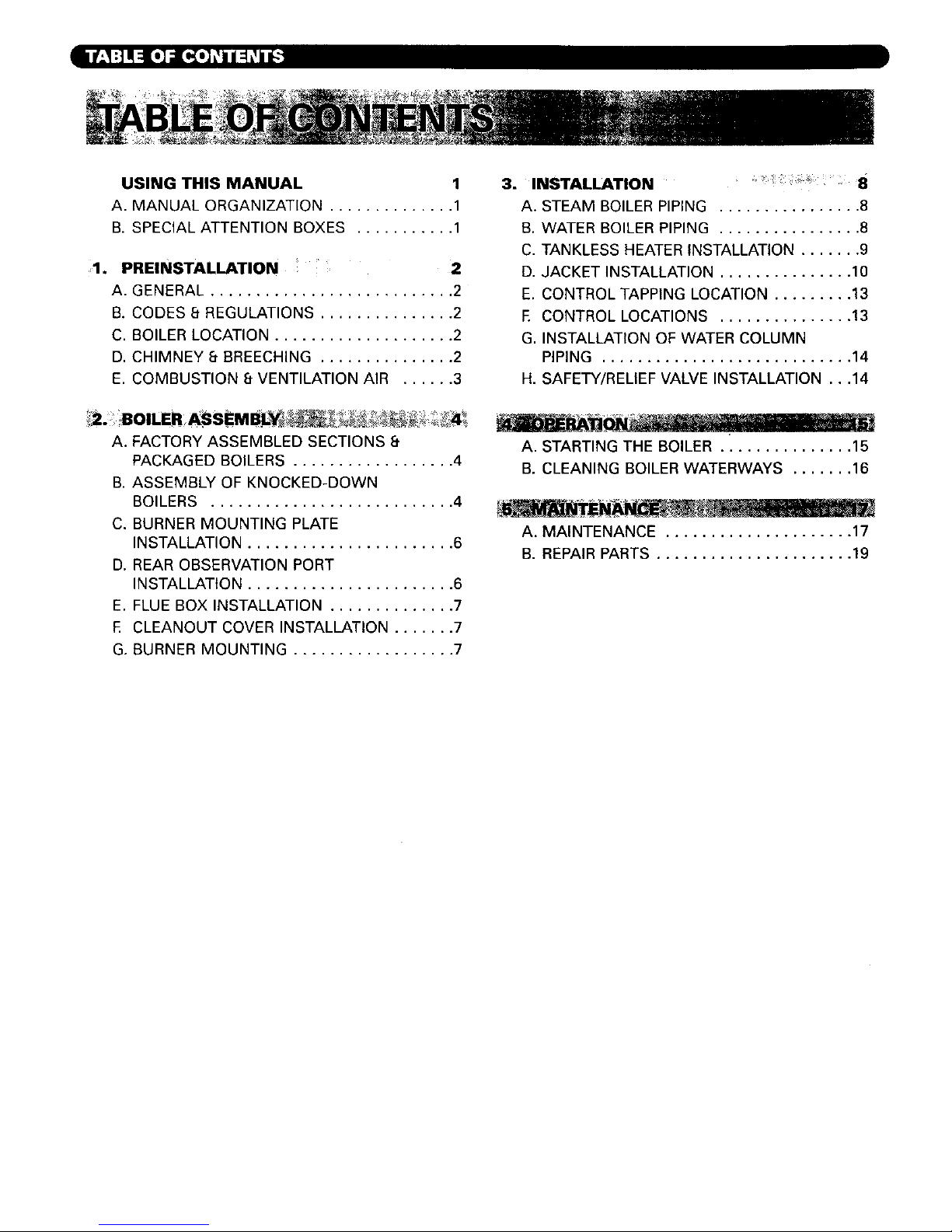
USING THIS MANUAL 1
A. MANUAL ORGANIZATION .............. 1
B. SPECIAL ATTENTION BOXES ........... 1
1. PREINSTALLATION " 2
A. GENERAL ........................... 2
B. CODES 8-REGULATIONS ............... 2
C. BOILER LOCATION .................... 2
D, CHIMNEY 8" BREECHING ............... 2
E. COMBUSTION 8.VENTILATION AIR ...... 3
3. INSTALLATION 8
A. STEAM BOILER PIPING ................ 8
B. WATER BOILER PIPING ................ 8
C. TANKLESS HEATER INSTALLATION ....... 9
D. JACKET INSTALLATION ............... 10
E. CONTROL TAPPING LOCATION ......... 13
E CONTROL LOCATIONS ............... 13
G. INSTALLATION OF WATER COLUMN
PIPING ............................ 14
H. SAFETY/RELIEF VALVE INSTALLATION ...14
A. FACTORY ASSEMBLED SECTIONS 8"
PACKAGED BOILERS .................. 4
B. ASSEMBLY OF KNOCKED-DOWN
BOILERS ........................... 4
C. BURNER MOUNTING PLATE
INSTALLATION ....................... 6
D. REAR OBSERVATION PORT
INSTALLATION ....................... 6
E. FLUE BOX INSTALLATION .............. 7
E CLEANOUT COVER INSTALLATION ....... 7
G. BURNER MOUNTING .................. 7
A. STARTING THE BOILER ............... 15
B. CLEANING BOILER WATERWAYS ....... 16
A. MAINTENANCE ..................... 17
B. REPAIR PARTS ...................... 19
Page 10

7,_1111_vlF±IL_tIY'..! II [e] *'{€'7-'1b,'_lV.J'-_III[*] L_
The Series TC Installation, Operation & Maintenance
Manual is divided into five basic sections:
I. Preinstallation (Sections A through E)
2. Boiler Assembly (Sections A through F)
3. Installation (Sections A through J)
4. Operation (Section A through B)
5. Maintenance (Sections A through B)
=J _.'-]"]:_a,]7±IW_*_IInd:::1L_IIII[o]b._II:{o),_4_
Throughout this manual you wi]l see special attention
boxes intended to supplement the insh_uctions and make
special notice of potential hazards. These categories
mean, in the judgment of the Peerless Heater Company:
Indicates a condition or hazard which will cause
severe personal injury, death or major property
damage.
Indicates a condition or hazard which may potentially
cause severe personal injury, death or major property
damage.
Indicates a condition or hazard which will or can
cause moderate personal injury or property damage.
Indicates special attention is needed, but not directly
related to potential personal injury or property
damage.
Page 11

'-'1 [_ :lOl:l;_r.*1
Series TC boilers are supplied completely knocked down
for field assembly, completely assembled as packaged
boilers or as assembled blocks of sections. All items
should be inspected for damage upon receipt and any
damage reported to the wholesaler and trucker. All
components should be stored in a clean dry area.
Im]! [o,l:lllVd_'_l::li"dt:'1 I:]:t:d=(e,];llO[,€
Carefully read these instructions, burner and controls
manuals before beginning work. This boiler must be
installed by a qualified contractor. The boiler warranty
can be voided if the boiler is not installed correctly.
:N [I'[e] I] _L,"Jl-'JR;| :[L"[I JW-'_IHi[I] _I.:
1,
2,
All work shall be performed in strict accordance with
the requirements of state and local regulating
agencies and codes dealing with boiler installations.
In the absence of such local requirements the
following should govern:
A.S.M.E. Section IV - "Heating Boilers"
A.S.ME Section VI - "Care and Operation Boilers"
ANSIfNFPA 31 - "Installation of Oil Burning
Equipment"
ANSI!Z223.1 - "National Fuel Gas Code"
ANSI/NFPA 70 "National Electrical Code"
A.SM.E. CSD-1 "Controls and Safety Devices for
Automatically Fired Boilers"
ANSI/NFPA 211 - "Chimneys, Fireplaces, Vents,
and Solid Fuel Burning Appliances"
If this boiler is to installed on combustible flooring.
Consult local building authorities for proper
installation, or in the absence of regulations consult
ANSI/NFPA 31, Section 4-4. Failure to comply with
this warning can result in a fire, severe personal
injury or death!
[OglI:.[o]lll::l:] li[oIo,Y,__l/[O]_
1. The boiler should be installed on a concrete floor or
pad. If a pad is used, it should be at least 2" high
and strong enough to support the boiler's weight. Do
not install electrical conductors of any type under the
boiler or pad. The pad must be as level and fiat as
possible.
Locate the boiler close to the chimney to minimize
the breeching length, but allow adequate clearance
for piping, service, maintenance and tanldass coil
replacement. A clearance of 36" on the sides of the
boiler and 48" in front of the boiler is recommended
for serviceability. The minimum clearance to
combustible materials, based on ANSI!NFPA 31,
Table 4-4.11 Clearances to Combustible Materials, is
as follows:
2
I Sides: 6"
2. Rear of Jacket: 6"
3. Front of Boiler: 24"
4. Top of Jacket: 6"
5. Vent/Chimney/Flue Box: 18"
]. Vent System Inspection:
a) Inspect the existing chimney or vent system.
Make sure it is in good condition.
b) Inspect the chimney liner and repair or replace if
necessary.
2. Vent System Installation:
a) The vent system and installation must be in
accordance with the current edition of the
American National Standard ANSI!NFPA 211,
"Chimneys, Fireplaces, Vents, and Solid Fuel
Burning Appliances" or applicable provisions of
the local building codes.
b) Always extend vent terminations three feet above
the roof line.
c) The breeching connection between the boiler
and chimney should be as short as possible with
a minimum number of elbows. [t should be
pitched upwards 1/4" per foot. The breeching
must be the same diameter as the boiler outlet
up to 16 section boilers and 18" diameter for 17
and 18 section boilers.
d) If extreme length, excessive number of turns or a
reduction in diameter is necessary, consult your
Peerless Heater Company representative for
recommendations.
3. Vent System Operation:
a) The vent system must be sized and installed to
remove all combustion products. If the vent
system is not properly sized, the burner may not
operate properly. This can cause poor
combustion or sooting to occur.
b)
c)
If the vent system terminates in any area where
wind-generated down drafts are likely, install a
suitable vent cap which can control wind effects.
This boiler is designed to fire only with a positive
pressure firebox with no more than 0.1" water
column at the boiler outJet before the slide
damper. If venting conditions cause a greater
back pressure, burner capacity may be reduced.
Consult the Peerless Heater Company for
verification of burner capacity under these
conditions. The breeching and vent may be sized
for negative, neutral, or positive pressure as
desired. However, negative pressure overfire can
cause lifting of the flame and poor combustion or
overheating of the boiler crown sheet.
Page 12

d) Breechingusedwithforceddraftboilersmustbe
sealedandofheavygaugesteelconstruction.
Breechingmustcomplywithallapplicablecodes
ofconstruction.
I::m [_o]Lv_l:_lk'li[o]b,_l.'livdqLlilllr-'ll[o]L_l F-'II:
Configuration of breeching and chimney on some
installations may result in a positive breeching
pressure. In these cases, the breeching must be
constructed of pressure tight material, Consult local
building authorities for proper installation. Failure to
comply with this warning can result in carbon
monoxide poisoning or a fire resulting in severe
personal injury or death.
1.
2.
Provide adequate air for combustion and ventilation.
Unless boiler room construction and natural air
infiltration supply all necessary combustion air,
provide an outside air opening or duct. The free
cross sectional area of the opening or duct shall meet
or exceed i square inch per 4000 Btuh input for all
installed appliances. At altitudes above 2000 feet,
increase this requirement by 4% per each thousand
feet above sea level.
3.
If motorized dampers are used on the combustion
and ventilation air openings, wire them such that
they must open in order for the boiler to operate.
They must include a switch that prevents the boiler
from operating if they do not open.
Page 13

"I_.'_-"I-'] 5F'ul:]led
2.
3.
Careful inspection should be made of all assemblies
to detect possible damage during shipment. Factory
assembled blocks of sections and package boilers are
hydrostatically tested at the factory to insure pressure
tightness. Before piping connections are made to the
boiler, hydrostatically retest boiler sections to detect
leaks that may have developed from rough handling
during shipment.
All completed boilers shall satisfactorily pass the
hydrostatic tests as prescribed by ASME Code,
Section I'_
a) Steam boilers - the assembled boiler shall be
subjected to a hydrostatic test pressure of not less
than 45 PSIG.
b) Water boilers - the assembled boiler shall be
subject to a hydrostatic test pressure of not less
than 1-I/2 times the maximum allowable
working pressure.
c) The required test shall not exceed the pressures
prescribed above by more than I0 PSI.
Maintain the test pressure while carefully checking for
leaks. If a leak is found it must be eliminated. Once
the cast iron sections have proven to be water tight
drain them and remove the plugs from any tappings
that will be used in service.
HOLES FOR MOUNTING LOWER
__ JACKET CHANNELS _
" 36-1/2" '1
Figure 1: Shim b Grout Under Angles to Provide
Full Bearing
RETURN
CONNECTION
BOSS
Remove the shipping lugs bolted to the ends of the
base angles and the straps from the draw rods to
angle base after the boiler is in place. Leave the
boiler on the angle iron base.The lifting lugs on
assembled blocks of sections must be removed for
the boiler to accept its jacket,
4. Remove left side jacket panels and check that the
cleanout covers are secure and gas tight.
:tll,__..'&ff__,d:]I_[e] ;I [(OTeIdN=ID_]_DIol_'_,Tl?!:{o]1IF-J_
Section Assembly
1.
Drilled and tapped steel angles are furnished to
provide a level footing, facilitate section assembly
and provide a means of attaching the jacket. Set the
angles in parallel position measuring 36-I/2" outside
of the angles as shown in Figure I. Shim the angles
to make them level and grout after the sections are
assembled.
2.
Place the back section in position on the angles as
shown in Figure 2. The end of the floor angle must
extend beyond the boss for the return connection by
up to 3/8" or be flush with the return connection boss.
Figure 2
3.
MIN.- FLUSH
MAX. 3/8"
Inspect the graphite port connector recesses and
rope groove for dirt and obstructions. Clean the port
connector recesses with a stiff wire brush. Apply the
spray-on adhesive supplied with the boiler to the
rope groove to hold the rope gasket in place during
assembly. Apply a length of rope gasket while
avoiding bends and twists. Ensure that the ends of
the rope extend past the clean-out cover opening as
shown in Figure 4.
Install large port connector with steel inner ring
into the upper port making sure that the inner ring
stays inside the port.
Page 14

4,
5.
Install two smaller port connectors in the lower
recessed ports.
Note: If port connectors will not stay in place: Use
spray adhesive, supplied with the rope gasket, to
hold the graphite port connector (with steel ring) in
place. Alternatively, hold the port connector in place
with a putty knife or similar tool, making certain to
remove the tool before the sections mate. Failure to
remove the tool may dent the port connector,
causing a leak.
Select the correct intermediate section (refer to Table
I), and slide it in place against the back section.
Ensure that the sections are plumb and the port
connectors properly seated in the port recess as
indicated in Figure 3. Install the draw rods and
hardware and tighten them lightly.
It is essential to locate tapped intermediate and
optional tankless heater sections, as shown in Table
1, in order to maintain steam quality and jacket fit.
6. Inspect the rope gasket to ensure that it remains in its
groove. Check the section alignment and port
connector position by looking through the ports, if
necessary, reposition the port connector by loosening
the draw rods and then retighten them. Check the
floor angles and section for alignment.
GOOD BAD
SECTIONS READY SECTIONS
FOR DRAW UP DRAWN UP
Figure 3: Section Alignment
7. Gently draw the sections together until the port
connectors are in full contact with both mating
surfaces. Make sure the port connectors stay inside
the boiler ports.
8.
Torque the draw rods as described below. Do not
completely tighten one side. Gradually work each
side until the correct torque is reached.
Torque Specifications for Series TC
Boiler with Graphite Port Connectors
Step 1 Upper Right
Step 2 Lower Left .
Step 3 Lower Right
Step 4 Upper Left .
Step 5 Upper Right
Step 6 Lower Left .
.... 25 ft. Ibs.
.... 25 ft. Ibs.
.... 25 ft. lbs.
.... 10 ft. Ibs.
.... 50 ft. Ibs.
.... 50 ft. lbs.
Step 7 Lower Right .... 50 ft. Ibs.
Step 8 Upper Right .... 75 ft. Ibs.
Step 9 Lower Left ..... 75 ft. Ibs.
Step i0 Lower Right . . .75 ft. Ibs.
9.
Step 11 Upper Left ..... 30 ft Ibs.
Step 12 UpperRight . . .125 ft. Ibs.
Step 13 Lower Left . . .125 ft. Ibs.
Step 14 Lower Right . 125 ft. Ibs.
Step 15 Upper Right . .125 ft. Ibs.
Step 16 Upper Left .... 40 ft. Ibs.
The boiler sections may not attain metal-to-
metal contact. This is acceptable using the
graphite port connectors. The torque
specifications listed above are only a
guideline. If any ports develop leaks during
the hydrostatic test, the torque can be
increased up to 200 ft Ibs. on the upper right
and 150 ft. Ibs. on both of the lower ports or
until the sections make metal-to-metal
contact. Additional torque after the sections
are in contact will not improve the seal.
Prepare the rope groove and gasket recess on the
intermediate section as described for the back
section in section 2B2 of this manual.
I0. Select the next appropriate section and repeat the
assembly process.
Hydrostatic Testing
II. Plug all openings in the boiler waterways and fill the
boiler with cold water to hydrostatically test for leaks
as indicated in section 2A2 of this manual.
12. While filling the boiler for hydrotest, RECHECK the
torque on all ports and tighten the draw rods if
Aecessary.
If any port connector leaks, tighten the draw rods
until it stops leaking or until either metal-to-metal
contact is made or the 200 ft. Ibs. limit on upper
right and 150 ft. Ibs. on lower ports is reached as
described in Step 8. Check the torque on draw rods
for adjacent ports.
13. When the boiler is ready to be put into operation for
the first time, the temperature should be brought up
slowly (low fire when applicable).
FIT ROPE GASKET IN
GROOVE WITH 1/8"
SHOWING AT JOINT
CONTINUOUS
LENGTH
OF ROPE GASKET
Figure 4: Rope Gasket Installation
5
Page 15

Table 1: Arrangement of Sections for Steam Boilers
4Section-F T H B
5Section-F-H-T-H B
6Section-F T H-T-H-B
7Section-F-T-H-P-T H B
8Section-F-T H P H-T-H-B
9Section-F T-H-P-H P T H B
10 Section-F-H-T H P H-P-T-H-B
11 Section-F H-T-H-P-T-H P-T-H-B
12Section-F-H-T H P-T-H-P-H-T-H-B
13Section-F-H-T H P H-T-H-P-H T-H-B
14 Section- F- H-T H- P- H-T- H- P-H-P-T-H-B
15Section-F-H T H-P-H-P-T-H P-H-P-T-H-B
16Section-F-H-T-H-P-H P-H-T-H-P-P H-T-H-B
17 Section- F- H-T- H- P- H- P- H-T- H- P- H- P- H-T H-B
18 Section- F- H - T- H- P- H P-H-P-T- H-P-H-P-H-T-H-B
Note: Tapped intermediate (T) are furnished for supply on steam boiler only. For water
boilers use plain intermediate sections (P) in place of tapped intermediate sections (T).
F - Front Section
T - Intermediate Section with 5" Tapping
H - Optional Intermediate Heater Section
P - Plain Intermediate Section
B - Back Section
Do not exceed 200 ft.-Ibs, torque on the upper right
side draw rods, 150 ft. Ibs. on the lower draw rods and
40 ft.-tbs on the upper left side draw rods.Tighten the
rods in the sequence shown in section 2B8.
Overtightening draw rods does not improve the
sealability of the joint. Excessive torque may damage
castings.
1.
2.
Cement the 3/8" diameter rope gasket into the
groove of the burner mounting plate with spray-on
adhesive. Install the 7/16" x 2-1/2" studs in the screw
seats around the opening in the front section. Install
the burner mounting plate insulation block in the
hole in the front section with the small flame
observation port cutout on the top left side. Place
the burner mounting plate over the block and force
the block inward until the studs extend far enough
through holes in the burner mounting plate to accept
the nuts. Tighten the nuts.
Use a long drill, awl, or other such tool for form
holes through the insulation block for four 1/4"
machine screws. Install the i/4" x 5" machine screws
through the holes in burner mounting plate,
supporting the insulation block on the inside to
prevent tearing. Install the 2" x 1-1/2" stainless steel
washers and nuts over the insulation block and
tighten lightly, being careful not to crush the
insulation. At the time of burner installation the
burner hole may have to be enlarged and shaped.
This may be done with a hacksaw blade.
I. Assemble rear obsewation port as follows:
a) Locate steel "flapper door," Item 6 as shown in
Figure 5. Drive Item 7, "expansion pin," into
hole in Item 1 to secure Item 6 in position.
b) Lift Item 6 up and install Item 2, "hex bolt."
c) Slide Item 3, "compression spring" over the hex
bolt and screw Item 4 "hex nut" to hex bolt.
d) Screw Item 5, "ball knob" into position and lock
location using Item 4 as a "jam" nut.
e) Adhere I/8" x 3/4" x 24" long insulating tape, as
shown, to observation port frame, Item I.
2. Screw the 5/16" x 1-I/2" studs into the screw seats
around the op_ning for the rear observation port in
the back section. Apply a thin layer of furnace
cement over the mounting flap and install the port
assembly. Install the washers and nuts and tighten.
3. Mount assembly to the back section of boiler.
4
3
6
INSULATINGTAPE
Figure 5: Rear Observation Port
Item 6 in Figure 5, must always be part of the assembly.
Check condition twice/year and replace as needed.
Page 16

l :N 3 KIJ :! :{o):| h'_F.'_IIt;1nn|;_1 i [o] _
Screw the 5/16" studs into the screw seats around the
flue box outlet on the back section. Place I/8" x 3/4" x
86" long, Type A, adhesive tape insulation over the
studs. Place the flue box in position and install the
washers and nuts, tightening the nuts uniformly. The
1/8" x 3/4" x 18" long, Type B, adhesive tape is installed
on the horizontal surface of the damper anchoring angle
on the bottom side of the flue box. Open the slide
damper all the way and leave ready for adjustment
during burner lightoff.
[€]l l:[lJ;|i_l:IH llVj[*llJ_,_illlL'_[€
Cleanout covers come insulated from the factory. Inspect
the insulation before installing. Prepare the rope in the
grooves at the top and bottom of the cleanout cover
openings between the sections to insure an air tight seal
when the covers are installed. Cleanout cover hex nuts
should be set at 15 Ibs. torque. Use Hi-Temp silicone
caulk around the cleanout covers to seal air tight.
Most large burners require support from the floor.
See Burner Manufacturer's Manual for such
specifications, if needed.
1.
2,
3.
4.
Remove the burner from its crate. Read the burner
instructions.
Insert (4) 3/8"-16 x 1 I/4" studs supplied with burner
mounting plate into the front plate holes.
Place the high temperature gasket on the burner
front plate and secure the burner to the front plate
with 3/8" fiat washers and hex nuts.
If the burner is supplied with a pedestal, install it to
the burner per the Burner Manufacturer's
Instructions. The pedestal provides additional
support and prevents the burner from sagging.
Page 17

_1 b._lll:!'_'W_ll:{o]lll_l:t I'_l'.lh_[_
1 Steam piping schedule is shown in Table 2. Pitch the
piping to allow condensate to t_ow in the same
direction as the steam. Refer to Figure 6 for an
acceptable steam piping arrangement. Swing joints
are recommended. For optimum circulation a return
yoke, as shown in Figure 8, should be used.
Table 2
Steam Boiler Piping
No. of 5"
Boiler Section Risers Header Equalizer
4 & 5 1 5" 2-112"
6 & 7 2 4 5" [ 2-1/2"
i6 2 I 6" €'
11 - 18 3 8" 4"
Spacing of steam risers must be checked for each
boiler installation.
STEAM HEADER SWING JOINTS
A
f /R_SER(S)
STEAM SUppLY
WHEN 3 RISERS
Table 3
Steam Boiler Feedwater Recommendations
I=B=R Minimum Condensate
Gross Evap Feedwater Receiver
Boiler Output Rate _ Pump Flow± Capacity 3
Model MBH GPM GPM Gallon
TC-04 [ 900 . 1.86 3.7 -- 37
TC-05 ] 1166 2.41 4.8 48
TC-06 1433 2.96 5.9 59
TC-07 [ 1699 3.56 _ 7.0 _ 70
TC-08 ! 1965 4.05 8.1 81
TC-09 . 523£ ' 4160 " 9.2 _ 92
TC-10 468 i ,15 lO.3 lO3
TC-1] 2764 _ .5.70 1i.4_ _114
TC-lg _o31 5.25 !a& _ !as
TC-13 _ 3297 ] 6.80 13.6 _ 136
--TC-14 T 335_ {. 7535_ 14/7 / 147
TC-15 + 3830 7.90 : 15.8 t 158
TC:16 ! _96 7 814,5 i6_. _69
TC17 V 4362 ! 9£10m 18d}_ 180 L
TC-18 4629 9,55 19.1 191
1 Evaporation rate based on heat of vaporization at 212 ° F,,970 BTU/Ibm
2. Minimum feedwater pump flow is based on 2 times evaporation rate
3. Condensate receiver capacities are based on 20 minute steam cycle. Chaa
shows actual capo¢ity and not gross receiver volume.
3. The front section has 3" tappings at the base for
installation of 3" close nipples and 3" caps. Removal
of caps allows flushing of sediment from boiler.
These recommendations are considered normal for
compact buildings, Where buildings are spread out,
additional receiver capacity may be necessary
because of the extended time required for
condensate to return to the receiver.
I:]! ih_l:_ll:l;t :{o]lll=l;tl'Jl'ZlL_[4
GRAVITY RE31JRN OR WATER FEED
CONNECTIONS AT OR ABOVE LOWEST
PERMISSASLE WATER LINE AND BELOW
NORMAL WATER LINE
Figure 6: Steam Piping
ALTERNATE PUMP
DISCHARGE
1. Piping for water boilers is shown in Figure 7. A
return yoke is provided as standard equipment for
each water boiler. Table 4 contains a pipe size
schedule for water boilers.
AIR REMOVAL
SUpPLy
CONNEC_DN
(LOCAllEDON
FRONTOF
BO_ER)
D/SCH/_GE PIPE
2. Feedwater requirements for steam boilers at full input
are shown in Table 3. Addition of water to the boiler
should be controlled by sensing the actual boiler
water level. One inch water column tappings are
provide on the front section to mount various low
and high water cutoffs and controllers.
CW. MAKEUp
RETURN
Figure 7: Water Piping
Page 18

Table 4
Water Boiler Piping
(Based on 20 ° A T System Temperature Drop)
Boiler Size Return Size Supply Size
TC-W-4 & 5 3 3
TC-W-6-9 4 4
TC-W-10 18 5 5
2. Series TC Return Yoke Assembly, Grooved Pipe (4 to
18 sections}
a) Cover edges and outer surface of the gasket with
a thin layer of petroleum-free silicone lubricant or
equivalent.
b) Install the gasket by placing the gasket over the
pipe and ensure that the gasket lip does not
overhang the pipe end.
Bring both pipe ends together, ensuring proper
alignment, and slide the gasket into position
properly centering it belween the grooved
portions of each pipe.
d) Place coupling housings over the gasket so that
the keys fully engage into grooves. Insert the
bolts into the couplings and tighten the nuts until
finger tight.
e) Tighten nuts alternately and evenly. Gasket
should not be visible after tightening•
Table 4A
Parts List
Item
•
Quantity Stock Code Description
I [ 6 __ 7656 Coupling 4"
2 . 1 7657 Coupling 5"
3 I 7658 Tee 4" x 4" x 5"
4 [ 2 - 7659 Tee 4"
8 i I 7663 Lube 4.5 oz.
Clean the heater flange to remove any dirt or rust. Install
the 7/16" x 1-1/2" studs in the screw seats around heater
opening. Place the heater gasket over the studs and
install the heater. Install the nuts and tighten them
evenly to ensure uniform gasket compression. Install the
operating control in one of the heater mounting plates.
This ensures quick burner response to hot water
demand. Figure Ii shows an acceptable piping
arrangement for multiple heaters.
GASKET_
OPERATING
CONTROL_
TAPPING
INTERMEDIATE
HEATER SECTION
Figure 8: Return Yoke Assembly
(4 to 18 Sections)
/
/
,(s)
OUTLET
Sm8HEATER
Figure 10: Tanklsss Heater
Before installing any controls or instrumentation on
the front panel, F1-F2, (refer to Figure 13) must be
installed.
Figure 9: Return Yoke Assembly - Individual Parts
Page 19

']_l_Jl_7i_[,]_l
HOT WATER SUPPLY
OPERATING
UNION
TEMPERATURE
TEMPERING
VALVE
GATE
VALVE
Figure 11: Tankless Piping
DJ nT'..Tq[q:llll Ildl,.'llf_,111'__ll[o]_
Boiler Assembly
The boiler must be completely assembled on base angles
supplied by Peerless Heater Company. These are drilled
and tapped to accommodate lower jacket channels.
Factory assembled blocks of sections are shipped on 6"
or 8" channel iron.
Control and Piping Installation
Any operating or limit controls to be located on the front
of the front section and the steam gauge glass must be
installed after front panel F2, refer to Fig. No. 13. All
other piping, burner and control connections may be
made before jacket installation.
Jacket Assembly (See Figure 12.)
1. Lower Channels: Locate lower channels and layout
on floor angles. Notches in channels are to
accommodate remaining stud from lifting lugs on
floor angles for factory assembled blocks of sections.
Ignore notches if boiler is not factory assembled.
Layout such that 5/16" hole on end of unnotched leg
of channels is at the front and rear of boiler, facing
upward. Boilers 15 through 18 sections have 3 piece
lower channels with center section only having hole-
to-mount channels to angles. Mount channels to
floor angles with 1/4" - 20 round head machine
screws and washers.
2.
Front Panels: Locate panel F2 over the front section
with the bottom corners supported by the lower
channels. Align holes and fasten with #I0 washer
bead sheet metal screws. Install panels FI and F2A
with #10 washer head sheet metal screws.
3.
Back Panels: Assemble right rear post to back panel
BI with #10 washer head sheet metal screws. Install
panel!post assembly on boiler. Assemble left rear
post to back panel. Align lower holes of right and left
posts with lower channel holes and join with #10
washer head sheet metal screws. Install panel B2
with sheet metal screws.
CHECK
VALVE
8" _r_R
UlaPLy
4,
5.
Upper Channels, 4 Through 7 Section Boilers:
Boilers from 4 through 7 sections have one piece
upper channels. These are installed and attached to
the top of front and back panels with 1/4" - 20 round
head screws, washers and nuts.
Upper Channels, 8 Through 18 Section Boilers:
These boiler sizes have two and three piece upper
channels supported at each splice by a bracket.
Assemble upper channels with splice pieces on the
floor with 1/4" - 20 round head screws, washers and
nuts. Assemble hardware hand tight. Install channel
assemblies on boiler to the top of the front and back
panels with 1/4" - 20 round head screws, washers
and nuts. Locate left support bracket and center over
splice and corresponding draw rods that allow
attachment of bracket to the boiler while overlapping
the splice in upper channels. Disassemble and install
splice hardware that align with slot in top of support
bracket. All holes will not align with slot.
Loosen nuts on draw rods to install brackets behind
washer, Level upper channel and re-tighten draw
rods nuts immediately to 40 ftJIbs, on left draw rods
and 125 ft./Ibs, on right draw rods, Install the right
support brackets in a similar manner. Check
alignment and tighten all hardware.
6. Side and Top Panels: Assemble knobs on left side
panels. Install panels by inserting the top first and
dropping the bottom into the groove made by the
lower channel.
Lay out top panels such that knockouts and
openings agree with the assembled boiler. After
layout has been checked, make necessary knockouts
and install panels.
Lay out and install right side panels similarly to top
panels. This completes the jacket assembly.
I0
Page 20

LEFT
REAR
POST
LH1
LH3
LH4
SUPPORT
BRACKETS
RIGHT
REAR
POST
B2
CHANNELS,
T3
T4
T5
T6
T7
3E
\UPPER
RH3
T1
RH4
RH5
F1
BASE ANGLES
(NOT INCLUDED
WITH JACKET)
Figure 12: Jacket Assembly
11
Page 21

FI_-"]_ ! mE_i['L r
Table 5: Jacket Schedule
Jacket Channel Carton
Upper
Channels
_ Lower Channels
oo
2
2 2 2 2
2 2
2 2 2 2 I i 2 I 4
1 1 2 1 4
10, ,21
lli 1 1 2 1 4
12 1 1 2 1 4
1318 1 1 1 1 l I 1 2 1 4 2 2 2 2
14 2 2 I i 2 i 4
15 2 2 2 2 2 4 2 4
16 2 2 2 2 2 4 2 4
17 2 2 2 2 2 4 2 4
2 2 2 2 J2 4 2 4
Channel Carton Hardware
{17) 1/4" - 20 x 3/4" Slot, RD, Head Machine, Screws, Zinc Plated
(17} 1/4" ID Washe_, Zinc Plated
(17) 1/4" - 20 H_ Nuts, Zinc Plated
(4) 5/8" [E Std. Washer
Table 5A: Jacket Schedule
Top & Side Cartons
Jacket Front & Back Carton *_
Left Side
Front Panels Back Panels "_ Top Panels Panels Right Side Panels
< _ _ C3 Chrome Knob
The front and back carton, which
consists of one (1) each of the above
listed items, is the same for all size
boilers¸
Hardware Bag:
(23) #10 x 1/2" Slot. Hex. Washer Head
8M Screws, Zinc Plated
(21) 1/4" - 20 x 1/2" Slot Rd. Head
Machine Screvss,Zinc Plated
{9) I14" - 20 Hex Nuts, Zinc Plated
(21) 1/4" I.D. Washer, Zinc Plated
8-32 x 1/4"
Machine Screw
Q_.
A I I I 1 I I 3 3
B 1 I 2 I I I 4 4
C I I I I
D I I I I 1 I 2 2
E I 2 I 4 4
F I I I 2 2
G 1 I 1 2 3 3
H 1 2 I I 4 4
l I 2
1 1 1 2 2
12
Page 22

:Ill .D] L_i II;To)nil If_,1:J:JI_[€"I I(o0D.Y±_l| [o] L_
Figure 13 shows the location of tappings for controls and
piping for both water and steam boiler.
3\! _
I
Tappi.g Tapping Steam Water
No. Size Boiler Boi]eT
i 3/4" Probe LWCO
2 I" Water Column Top Air Removal
3 3/4" Manual Reset Hi Limit.
Operating Control &
Steam Gauge
4 314" -- Operating Control
5 3/4" Water Glass (2) Manual Reset Hi Limit (Top)
Temp/Press Gauge (Bottom)
6 114" Overflre Pressure Tap Overflre Pressure Tap
7 i" Water Column Bottom Water Column Bottom
1-1/2 'r Inspection Tapping - Top
8 3/4" Tankless Heater O]_ra_ng Tankless Heater Operating
Control (Located in Heater Control (Located in Heater
Mounting Plate) Mounting Plate)
Figure 13: Tapping Locations
I_ [e(0]t_/l:Te]g [0I#;_IID]L_[,
Figure 14 shows the suggested location of limit and
operating controls.
MANUAL RESET
HIGH
OPERATING
CONTROL
STEAM
PRESSURE
GUAGE
Steam Boiler Control Locations
AIR REMOVAL
MANUAL RESET /CONNECTIONS
HIGH LIMIT _ _ L.W.C,O.
OPERAT'N ,.........
CONTROL _'---_[_ 0"_ ___1_ WATER
PROBE/ =_
L.W.C.O.
II
......... _L_
(OPT.) ' -. k:2_ 1,,
BALL
VALVE
(OPT.)
TEMP/PRESSURE
GUAGE
Water Boiler Conll"ol Locations
Figure 14: Control Locations
13
Page 23

L.W.C.O.
1"PIPING
__A?E OPT')
L.W.C.O.
(OPT.)
R
NE
GUAGE
GLASS
I" BALL
VALVE
(OPT.)
Series TC Series boilers are available with a variety of
water level control devices. Figure 14A shows a typical
water column piping arrangement. For all installations,
the 1"x 7-I/2" hydronic nipple is installed in the lower
water column tapping. The remaining hydronic nipple is
installed above the control device.
Figure 14A: Typical Water Column
Piping Arrangement
i-'ll _r_,l_l_llL'J I:t:llll:llV/_,lliVJ=l [IL_I.1F:IlI:_I/[0]L'
The safety relief valve is located in the 3" tapping at the
top of the rear section for both steam and water boilers.
Water and steam b-irn cartons contain relief valves and
fittings.
Relief valve discharge piping must be piped to avoid
exposure of persons to hot liquid or vapor, see
Figure 15. Never install any type of valve between the
boiler and the relief valve,
SUPPORT DISCHARGE PIPING SO AS
TO AVOID STRAIN ON VALVE BODY
RELIEF OR SAFETY VALVE.
DO NOT REMOVE RATING
OR WARNING TAGS.
MOUNT AS SHOWN.
DISCHARGE PIPE SIZE TO
EQUAL VALVE OUTLET,
DO NOT RESTRICT FLOW.
DISCHARGE SO AS TO
AVOID EXPOSURE OF
PERSONS TO HOT
LIQUID OR VAPOR.
LEAVE OPEN END
VISIBLE FOR PERIODIC
INSPECTION FOR SLOW
LEAKAGE OR DRIPS.
Figure 15: Safety Relief Valve Installation
14
Page 24

r:! t-'_if:1;t/h_[Cli|:l= I:{e]lq:l"
1. Check the piping.
a) Water/Steam Piping
i. The Boiler must have been hydrostatically
tested.
2. Check the attached piping for joint tightness.
3. Continue monitoring as you proceed through
start up.
b) Gas Piping
1. Make sure the gas system piping and the
connections to the boiler Gas Control Train(s)
have been leak tested.
2. After the boiler is in operation, check the
tightness of all joints in the boiler gas piping
with a soap suds solution.
3. Purge the gas piping of all air up to the boiler
Gas Control Train.
c) Oil Piping
1. Check the oil piping visually. Make sure all
joints are tight.
2. When the burner is firing, check the suction
line and return line pressures.
3. If the pressure exceeds the allowable pressure
in the Burner Manual or if the suction line
vacuum is higher than allowable, correct the
piping as needed to bring the suction line and
return line pressures within acceptable range.
4. Excess pressure can causepump seal failures.
Excess vacuum will cause fuel flow problems
with the burner oil pump.
2. Fill the boiler.
a) Steam: Fill the boiler to the normal water line.
I. Gravity Systems and Pumped Return with
Condensate Units - Fill to the normal water
level mark on front jacket panel.
2. Pumped Return with Boiler Feed Unit - Fill
the boiler using the boiler feed unit. Fill level
will depend on the control being used, but
should be at the normal water level mark on
front jacket panel.
3. Fill the boiler.
a) Water: Fill the boiler and system.
1. Fill the system with fresh water only. If the
water hardness is high, use water treatment
to reduce the deposition of minerals in the
boiler.
Check the system for leaks and make sure the
automatic fill valve (if used) and the expansion tank
are oprating correctly. Leakage or weeping of the
relief valve will cause make-up water to be added to
the system. Excessive make-up water will damage
the boiler and system components due to liming and
oxygen corrosion.
2. If the system requires antifreeze, use only
antifreeze designed for hydronic systems.
These contain inhibitors to prevent corrosion
of the boiler and system components. Do not
use ethylene glycol or automotive antifreezes.
• Make sure the antifreeze supplier can
provide periodic inhibitor check service.
• If automatic fill is used, the system will
have to be checked periodically to make
sure the antifreeze concentration has not
been diluted below design level.
• Local codes may require the use of a
backflow preventer or manual fill only
with separation from the cii_ supply.
• Consider the minimum temperature of
potential exposure for the system when
deciding on the antifreeze concentration.
A concentration of 50% generally
provides protection from freezing down to
-30°E
3. Purge the air from the system.
4. Run burner check-out.
a) Before firing the burner, slide the Slide Gate
Damper on the rear flue box all the way down
(full open).
b) Follow the instructions in the Burner Manual for
starting the burner, adjusting air openings and
fuel rates. Perform ignition system and flame
supervisory control test and checkout as
described in the manual.
c)
After burner is set at rate, close the damper until
the pressure reading at the test opening in the
rear flue box is between 0.0" wc and 0.1" wc
positive.
d)
Wl_en a barometric draft regulator is installed in
the venting system, adjust the boiler damper for
0.0" wc pressure reading at the damper. Adjust
the draft regulator for -0.05" wc draft between
the boiler damper and the draft regulator.
On installations with high draft, do not leave the
boiler with a negative draft reading at the rear flue
box or draft damper. High negative draft can pull the
flame up into the boiler crown steet and overheat the
iron.This can result in cracked sections or shortened
boiler life.
e) Adjust the burner as needed for a CO 2
reading of:
I. Oil burners: 12% to 12.5% or 1% less than
the level at which the smoke reading goes
above a trace on the Bacharach scale.
2. Natural gas burners: 9% to 10% with CO less
than 50 ppm.
15
Page 25

5. Check boiler controls.
a) Limit and Operating Controls
1. Lower the setting of each control until the
burner shuts down.
b)
Low Water Cutoffs
I. Test probe type controls by using the Push-
to-Test Button.
2. Test float type controls. ASME CSD-1 requires
the control to be piped with Test-n-Check
valves in order to allow isolation for test.
c) Follow additional instructions in the Burner
Manual for proving the burner component
operation.
d) Check all controls to make sure they function
correctly.
e) After all controls have been proven, set the
Operating and High Limit Controls to the set
point desired.
Steam Boilers
1,
The boiler must be completely assembled before
cleaning. The burner must be installed and made
operational with the operating, limit and safety
controls functional. Combustion should be adjusted
to prevent sooting of the boiler flues.
2. Final burner adjustment is to be made after cleaning.
Plug any unused boiler tappings and install gauge
glass and safety valve.
3. Install a 2" skim valve and fittings in the 6" N.PT.
tapping of the front section.
4, Clean the boiler as described below no later than
one week after the initial start-up. Cleaning will be
more effective if the boiler operates a day or two to
loosen sediment and impurities in the system.
Cleaning the boiler requires the use of very hot water
and corrosive chemicals. Use care when handling to
prevent injury.
5. The boiler must be cleaned to remove any
accumulation of oii, grease, sludge, etc. that may be
in the system. These substances can cause foaming
and surging of the boiler water, producing unstable
water line and water carryover to the system.
6. Connect a 2 inch drain line off of the skim valve, run
to a point of safe discharge.
7.
8.
Close all valves to the system. Provide a means of
continuous fresh water to the boiler for the cleaning
process.
Open the skim valve. Fill the boiler until water begins
to flow out of the valve.
9.
Use common washing soda (such as Arm and
Hammer Super Washing Soda). Mix the soda with
water in a 10 quart pail and pour into the boiler
through the safety valve tapping. Use a proportion of
one (I) pound of washing soda for each 800 square
feet EDR net boiler rating.
10. Turn burner on and allow the boiler water to heat up
to just below steaming (180 ° to 200°F). Cycle the
burner to maintain temperature during skimming. Do
not allow the boiler to steam. Steaming mixes up the
contaminants in the water instead of floating them at
the surface.
11. Open the make-up water valve to continuously feed
water to the boiler. Allow water to flow out the skim
tapping.
12. Continue skimming the boiler until the water flowing
from the skim tapping flows clear. This will take
some time, possibly several hours for a dirty system.
13. After skimming is complete, close the skim valve and
turn off the boiler.
14. Close the make-up water valve and open the boiler
blowdown valves.
15. Drain the boiler completely then refill and drain
again one or two times to make sure all of the soda
has been washed out.
16. Restore piping to normal. Pipe a nipple and cap in
the skim valve.
17.
Note: Ifthe gauge glass becomes dirty again, this
indicates more contaminants have worked loose in
the system. Repeat the cleaning and skimming
process as needed to clean the system.
Do not leave the boiler unattended while firing during
the cleaning cycle,
Take great care not to allow the water level to drop
below the bottom of the gauge glass or to allow fresh
water make-up to flow in too fast.This will avoid the
possibility of causing the boiler sections to fracture.
16
Page 26

Do not store or allow combustible or flammable
materials near the boiler. Substantial fire or explosion
hazard could result, causing risk of personal injury,
death or property damage.
Do not use this boiler if any part of it has been under
water. Immediately call a qualified service technician
to inspect the boiler. Any part of the control system,
any gas control or any burner or gas component
which has been under water must be replaced.
Should overheating occur or the fuel supply fail to
shut off: Shut off the fuel supply at a location
external to the boiler. Do not turn off or disconnect
the electrical supply to the pump. Immediately call a
qualified service technician to inspect the boiler for
damage and defective components.
1. Placing boiler in operation.
a) Start up the Burner/Boiler per the Burner Manual
and the insh'uctions in this manual on starting
the boiler.
b) Prove the correct operation of all controls on the
boiler and burner as outlined below.
c) Check the operation of the ignition and flame
proving controls as described in the Burner
Manual.
d) Test the limit and operating controls to assure
they are operating correctly.
e) Inspect and test all low water cutoffs.
f) Test the safety relief valve(s) using the procedure
given by the valve manufacturer on the valve tag.
g) Visually inspect the burner and pilot flames (if
applicable).
2. To shut down the boiler.
a) Turn off Burner.
b) Open main line power disconnect switch to
boiler/burner.
c) Close fuel shut-off valves.
d)
To take boiler out of service if the boiler and
system are not to be used when temperatures are
below freezing:
I. Shut off make-up water supply and drain the
boiler and system completely.
2. Open main line power disconnect switch to
boiler/burner. Remove the fuses or secure the
switch so that the power cannot be turned on
accidentally.
3. Do not use ethylene glycol antifreeze in a
boiler system.
4. Be certain that the boiler and system are
refilled before returning to service Follow the
instructions in this manual and the burner
instructions to operate.
Before servicing the boiler:
• Turn off all electrical power to the boiler.
• Close the Gas Service Valve and Oil Shut-Off Valve.
• Allow the boiler to cool if it has been operating.
• Label all wires prior to disconnection when
servicing controls. Wiring errors can cause
improper and dangerous operation. Verify proper
operation after servicing.
3. Maintenance - Annual
a) Before the start of each heating season,
inspect and make all necessary adjustments to
insure proper boiler and burner operation. Use
the maintenance and inspection procedures
following.
b) Inspect the Venting System
1. Check the chimney or vent to make sure it is
clean and free from cracks or potential leaks.
2. All joints must be tight and sealed.
3. The vent connector must extend into, but
not beyond the inside edge of the chimney
or vent.
c) Inspect the Boiler Area
1. The boiler area must be clean and free from
combustible materials, gasoline or any other
flammable liquids or vapors.
2. The combustion air openings and the area
around the boiler must be unobstructed.
d) Inspect boiler flueways and burner for
cleanliness. If cleaning is required, use the
following procedure.
I. Turn off all electrical power to the boiler.
2. Remove left jacket panels. Remove deanout
cover plates on each flueway.
3. Brush the boiler flue areas through cleanout
openings.
4. Remove the burner and burner mounting
plate. Remove any scale or soot from the
combustion chamber by means of vacuum
cleaning or other available means.
5. Reinstall the burner mounting plate, burner
and all cleanout cover plates. Make sure all
sealing rope and seals are in good condition.
Replace sealing rope if necessary.
6. Reinstall all jacket panels.
e) Inspect the boiler and piping for signs of leaks.
Check to see if there are signs of heavy make-up
water addition to the system.
17
Page 27

f) When placing boiler into operation, follow
burner manual, all instructions supplied with the
boiler and the instructions in this chapter.
g) Test the operation of all limit controls, float
controls and ignition components.
4. Monthly Maintenance
a) Inspect the burner and pilot flames.
b) Inspect the boiler and system for any signs of
leakage or excessive make-up water usage.
c) Inspect and check the operation of the venting
system.
5. Daily Maintenance
a) Inspect the boiler area to make sure the area is
free from combustible or flammable materials
and that there are not obstructions to the flow of
air to the boiler or combustion air openings to
the room.
b) Make sure there are no signs of abnormal
operation, such as overfilling or leakage.
Be vary careful when adding water to a hot boiler.
Add very slowly or, if possible, allow the boiler to
cool nautrally before adding water.
If an excessive loss of water occurs, check for a leak
in the piping and correct th problem. Excessive
make-up water will cause corrosion and damage to
the boiler.
STEAM BOILERS: Do not place cold boilers in
service on a hot steam line or severe damage may
occur to boiler and piping. Keep cold boilers valved
off line, fire until boiler reaches line pressure and
then open steam main isolation valve. Steam entering
a cold boiler cools quickly causing severe steam
hammer. Boilers not valved Off the system should
have an overflow installed to prevent idle boilers
from flooding. If this is not done, cold boilers must
be heated to near steaming conditions (210°F) and
then drop water level to normal.
WATER BOILERS: Avoid thermal shock of water
boilers. Establish water circulation through the boiler
before starting burner. Where hot standby is required,
special piping and operation procedures are
required. Consult your Peerless Heater Company
representative.
18
Page 28

Co
_'J!
t:
3
D"
11
19_
17
36 34....-..-.-_
35
9
15
35
39
34
5 4
29
1
28
2
27
21
13B
41
40 37 _/
I I
1
38
24
25
20
o_
_oe
_.._ __.
_ • _
5' _.._
_o _cr
c_ _3
- _
CJ"_
,.-._t.,Q
m m
g ,,D_
g_
_.t_
Page 29

Table 7: Series TC Repair Parts
1 !Front Section 76000
Intermediate Section 76002
2 lnlermediate Section w,Heater Connection 76004
4 Intermediate Section w, Supply Connection 76003
5 Back Section 76001
Flue Collector Assembly includes: Flue Collector, Slide Damper and Angle Bracket
76060
76061
i 76062
i 76063
7664
7679
7680
76064
76075
!
I 74019
i 76073
i 76074
I 7631
7622
51556
86
55521
Flue Collector Assembly (4-6 Section)
9 Flue Collector Assembly (7 8 Section)
Flue Collector Assembl_, (9 13 Section)
Flue Collector Assembly (14 18 Section)
Slide Damper Only {4-8 Section)
i0 Slide Damper Only (9-13 Section}
i Slide Damper Only (14-18 Section)
11 i 16" to 18" Increaser (17 18 Section)
12 Tankless Coil Cover Plate Assembly
13 Tankless Coil Cover Plate Gasket
13A TanMess Coil (8 GPM)
13B i Tankless Coil (12 GPM)
Cleanout Cover Plate Assembly Includes:
Cleanout Plate, Insulation, Rope and Hardware
15 Cleanout Cover Plate Assembly
16 Cleanout Cover Plate Bolts
17 Cleanout Cover Plate Nut
18 Cleanout Cover Plate Washer
19 !Rope Sea[ (3/8" Dia x 3 3/4 ft. Long)
Burner Mounting Plate Assembly Includes:
Burner Mounting Plate Observation Port Glass, and Cover
Burner Mounting Plate Assembly 7G/4"
76028
Burner Mounting Plate Assembly 8" 76023
Burner Mounting Plate Assembly - 9" 76027
20 Burner Mounting Plate Assembly - i0-i/4" (Web-JB2) 76026
Burner Mounting Plate Assembly I0 i/4" (GPR10.1) 76025
Burner Mounting Plate Assembly - 10-i/4" (STD) 76024
Burner Mounting Plate Assembly - 12-1/2" 76022
Burner Mountinq Plate Hardware I 7653
21 !Burner Insulating B}oek ! 76029
Burner Insulating Block Hardware 7720
22 Observation Glass Only 7648
23 Observation Glass Gasket 7650
24 Observation Glass Gaskel 7649
25 i Observation Glass Retainer 7651
26 Observation Cover Plate 7677
27 Rope Seal (3/8" x 7 ft Long) 55521
28 Upper Graphite Port Connector 7655
29 Lower Graphite Port Connector
51211
!
7621
51567
7289
55485
7632
7722
334 Rope Seal (1/2" x 7 ft Long) Between Sections
5/8" x 11" Draw Rod
5/8" Hex Nuts
35 ] 5/8 I' Washer
i Spray Adhesive
36 Rear Observation Port Assembly
- I Rear Observation Port Hardware
Steam Trim and Controls
_ 3-1/2" Steam Gauge w/Internal Syphon
Gauge Glass Set
1-1/4" Safely Relief Valve 15 PSI (4-5 Section)
1-1/2" Safety Relief Valve 15 PSI (6-7 Section)
I 2" Safely Relief Valve 15 PSI (8-10 Section)
39 2-1/2" Safely Relief Valve 15 PSi (11-13 Sedion
3" Safely Relief Valve 15 PSI (14-16 Section)
2-1/2" Safety Relief Valve 18 PSI (17 18 Section
40 PA404A Operating Contro
41 L404C Limit Control
51769
50521
50508
505O9
50503
50504
5O5O5
50511
50549
5O538
Water Trim and Controls
42 Pressure_emperature Gauge 55736
3/4" - 30 PSI Water Relief Valve (4 Section) : 51300
l" - 30 PSI Water Reie Vave 4-6Saction i 51301
39 1-1/4" 30 PSI Water Relief Valve (7 10 Section) 51302
1-1/2" - 30 PSI Water Relief Valve (11-13 Section) 51303
ve (15 18 Section) 51304
51702
45 LgOO6E Limit Control 51570
2O
Page 30

Series TC
Oil, Gas
Gas/Oil Boilers
Installation,
Operation
Maintenance
Manual
TO THE INSTALLER:
This manual is the property of the owner and must
be affixed near the boiler for future reference,
TO THE OWNER:
This boiler should be inspected annually by a
Qualified Service Agency.
member
HI Division ASME
of gama
PEERLESS"
CAST IRON BOILERS
PEERLESS HEATER COMPANY
231 NORTH WALNUT STREET- BOYERTOWN, PA 19512-1021 . PHONE 610-367-2153
www.peerless-heate_com
THE PREFERRED HEATING CHOICE
@2002 Peerless Heater Company TC8001 R1 (10/02-1M)
Printed in U,S.A,
 Loading...