

Page 1

Installation and Assembly:
Peerless Ultra-Thin Flat Mount for 37" - 65" (94 - 165 cm)*
Flat Panel Displays
Model: SUF661
*Display Compatibility Requirements
• The depth of this mount (0.19") may not provide
suffi cient space for proper ventilation on some displays.
Please refer to the manufacturer's requirements for
mounting your display before installation.
• The display must have a fl at mounting surface, or the
mounting holes need to be on the furthest back surface
of the display.
• Input/Output connection must be properly oriented to
accommodate mounting 0.19" from the wall.
2300 White Oak Circle • Aurora, Il 60502 • (800) 865-2112 • Fax: (800) 359-6500 • www.peerlessmounts.com
Max UL Load Capacity:
150 lb (68kg)
ISSUED: 04-01-11 SHEET #: 9029-2 07-27-11
Page 2
NOTE: Read entire instruction sheet before you start installation and assembly.
WARNING
• Do not begin to install your Peerless product until you have read and understood the instructions and warnings
contained in this Installation Sheet. If you have any questions regarding any of the instructions or warnings, for US
customers please call Peerless customer care at 1-800-865-2112, for all international customers, please contact
your local distributor.
• This mount is designed to attach the display 0.19" from the wall. Please refer to manufacturer's installation guide
recommendations for required distance from wall to avoid risk of injury or property damage.
• This product should only be installed by someone of good mechanical aptitude, has experience with basic building
construction, and fully understands these instructions.
• Make sure that the supporting surface will safely support the combined load of the equipment and all attached
hardware and components.
• Never exceed the Maximum UL Load Capacity. See page one.
• If mounting to wood wall studs, make sure that mounting screws are anchored into the center of the studs. Use of
an "edge to edge" stud fi nder is highly recommended.
• Always use an assistant or mechanical lifting equipment to safely lift and position equipment.
• Tighten screws fi rmly, but do not overtighten. Overtightening can damage the items, greatly reducing their holding
power.
• This product is intended for indoor use only. Use of this product outdoors could lead to product failure and personal
injury.
• This product was designed to be installed on the following wall construction only;
WALL CONSTRUCTION HARDWARE REQUIRED
• Wood Stud Included
• Wood Beam Included
• Solid Concrete Included
• Cinder Block Included
• Metal Stud Contact Qualifi ed Professional (not evaluated by UL)
• Brick Contact Qualifi ed Professional (not evaluated by UL)
• Other or unsure? Contact Qualifi ed Professional (not evaluated by UL)
Tools Needed for Assembly
• stud fi nder ("edge to edge" stud fi nder is recommended)
• drill
• 5/16" (8mm) bit for concrete and cinder block wall
• 5/32" (4mm) bit for wood stud wall
• level
Table of Contents
Parts List.................................................................................................................................................................................3
Installation to Wood Stud Wall ............................................................................................................................................ 4,5
Installation to Solid Concrete/Cinder Block walls ...................................................................................................................6
Installing Display Screws ........................................................................................................................................................7
Mounting Flat Panel Display ...................................................................................................................................................8
2 of 29
ISSUED: 04-01-11 SHEET #: 203-9029-2 07-27-11
Page 3

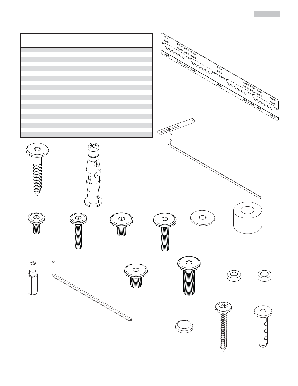
Before you begin, make sure all parts shown are included with your product.
A
r
Parts may appear slightly different than illustrated.
Parts List
Description Qty. Part #
wall plate 1 046-P1202
locking arm 1 046-P1212
B
wood screws 6 500-1090
C
concrete anchors 6 590-0320
D
M5 x 12 mm hex screw
E
M5 x 25 mm hex screw
F
M6 x 12 mm hex screw
G
M6 x 25 mm hex screw
H
.725" washer
I
3/4" spacer
J
4 mm security driver
K
4 mm security allen wrench
L
M8 x 12 mm hex screw
M
M8 x 25 mm hex screw
N
M5 x 1/8" spacer
O
M6 x 1/8" spacer
P
cloth bumper
Q
security wood screw
R
S
C
alligator ancho
®
D
4
4
4
4
4
4
1
1
4
4
4
4
2
1
1
560-1732
560-1733
560-1734
560-1735
540-9478
540-1059
560-1133
560-9646
560-1736
560-1737
046-0223
046-0224
570-0051
520-1092
590-0097
A
B
E
K
L
F
G
M
H
3 of 29
I
J
OP
N
QRS
ISSUED: 04-01-11 SHEET #: 203-9029-2 07-27-11
Page 4
Installation to Double Wood Stud Wall
WARNING
• Installer must verify that the supporting surface will safely support the combined load of the equipment and all
attached hardware and components.
• Tighten wood screws so that wall plate is fi rmly attached, but do not overtighten. Overtightening can damage the
screws, greatly reducing their holding power.
• Never tighten in excess of 80 in. • lb (9 N.M.).
• Make sure that mounting screws are anchored into the center of the stud. The use of an "edge to edge" stud fi nder
is highly recommended.
• Hardware provided is for attachment of mount through standard thickness drywall or plaster into wood studs. Installers are responsible to provide hardware for other types of mounting situations (not evaluated by UL).
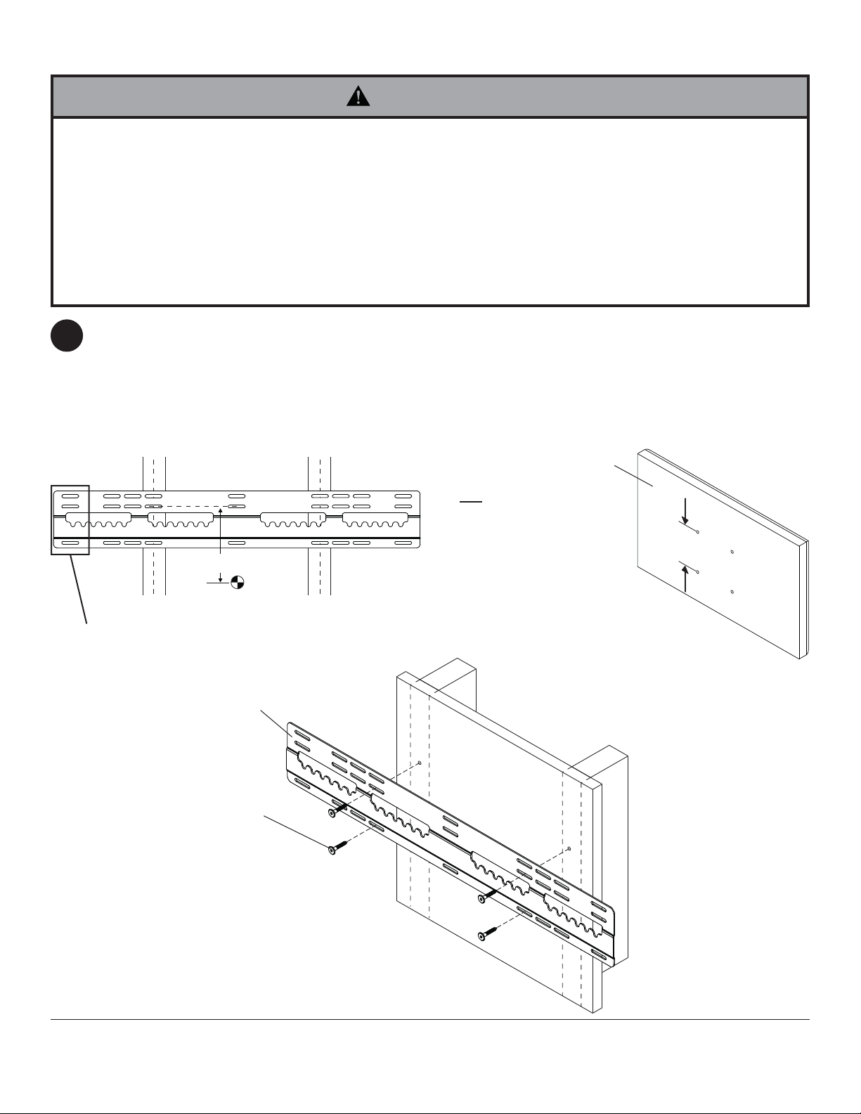
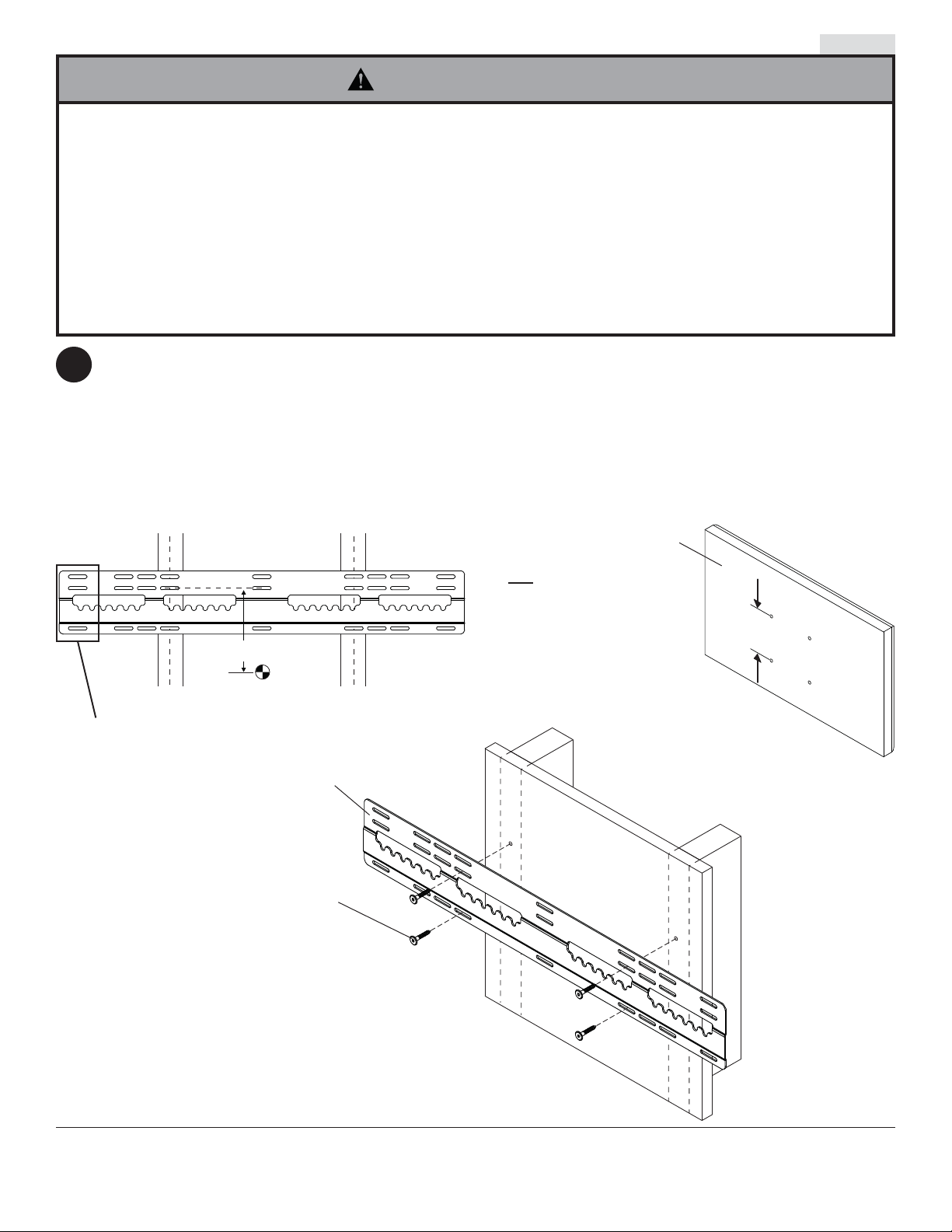
Wall plate (A) can be mounted to two studs that are 16", 20", or 24" apart. Use a stud fi nder to locate the edges
1
of the studs. Use of an edge-to-edge stud fi nder is highly recommended. Based on their edges, draw a vertical
line down each stud’s center. Place wall plate on wall as a template. The top mounting slots should be located
X" above the desired display center as shown in fi gure 1.1 and 1.2. Level plate, and mark the center of the four
mounting holes. Make sure that the mounting holes are on the stud centerlines. Drill four 5/32" (4mm) dia. holes
2" (51mm) deep. Make sure that the wall plate is level and secure it using four wood screws (C) as shown
in fi gure 1.3.
fi g. 1.1
XXX
XXX
XXX
Y
()
Y = distance between
display mounting holes
+ 1.75"X =
2
X"
NOTE: When mounting wall
plate (A) to two studs, do not
use center mounting holes or
outer mounting holes.
fi g. 1.3
A
C
DISPLAY
fi g. 1.2
Y"
4 of 29
ISSUED: 04-01-11 SHEET #: 203-9029-2 07-27-11
Page 5

Installation to Triple Wood Stud Wall
WARNING
• Installer must verify that the supporting surface will safely support the combined load of the equipment and all
attached hardware and components.
• Tighten wood screws so that wall plate is fi rmly attached, but do not overtighten. Overtightening can damage the
screws, greatly reducing their holding power.
• Never tighten in excess of 80 in. • lb (9 N.M.).
• Make sure that mounting screws are anchored into the center of the stud. The use of an "edge to edge" stud fi nder
is highly recommended.
• Hardware provided is for attachment of mount through standard thickness drywall or plaster into wood studs.
Installers are responsible to provide hardware for other types of mounting situations (not evaluated by UL).
Wall plate (A) can be mounted to three studs that are 16" apart. Use a stud fi nder to locate the edges of the studs.
1
Use of an edge-to-edge stud fi nder is highly recommended. Based on their edges, draw a vertical line down each
stud’s center. Place wall plate on wall as a template. The top mounting slots should be located X" above the desired
display center as shown in fi gure 1.4 and 1.5. Level plate, and mark the center of the six mounting holes. Make
sure that the mounting holes are on the stud centerlines. Drill six 5/32" (4mm) dia. holes 2" (51mm) deep. Make
sure that the wall plate is level and secure it using six wood screws (C) as shown in fi gure 1.6.
fi g. 1.4
C
X"
A
DISPLAY
Y
()
Y = distance between
display mounting holes
+ 1.75"X =
2
fi g. 1.6
fi g. 1.5
Y"
5 of 29
ISSUED: 04-01-11 SHEET #: 203-9029-2 07-27-11
Page 6
Installation to Solid Concrete or Cinder Block
WARNING
• When installing Peerless wall mounts on cinder block, verify that you have a minimum of 1-3/8" of actual concrete
thickness in the hole to be used for the concrete anchors. Do not drill into mortar joints! Be sure to mount in a
solid part of the block, generally 1" minimum from the side of the block. Cinder block must meet ASTM C-90
specifi cations. It is suggested that a standard electric drill on slow setting is used to drill the hole instead of a
hammer drill to avoid breaking out the back of the hole when entering a void or cavity.
• Two wood screws (C) must be installed into wall plate (A) in each segment as shown in detail 1, or product may fail.
• Concrete must be 2000 psi density minimum. Lighter density concrete may not hold concrete anchor.
• Installer must verify that the supporting surface will safely support the combined load of the equipment and all
attached hardware and components.
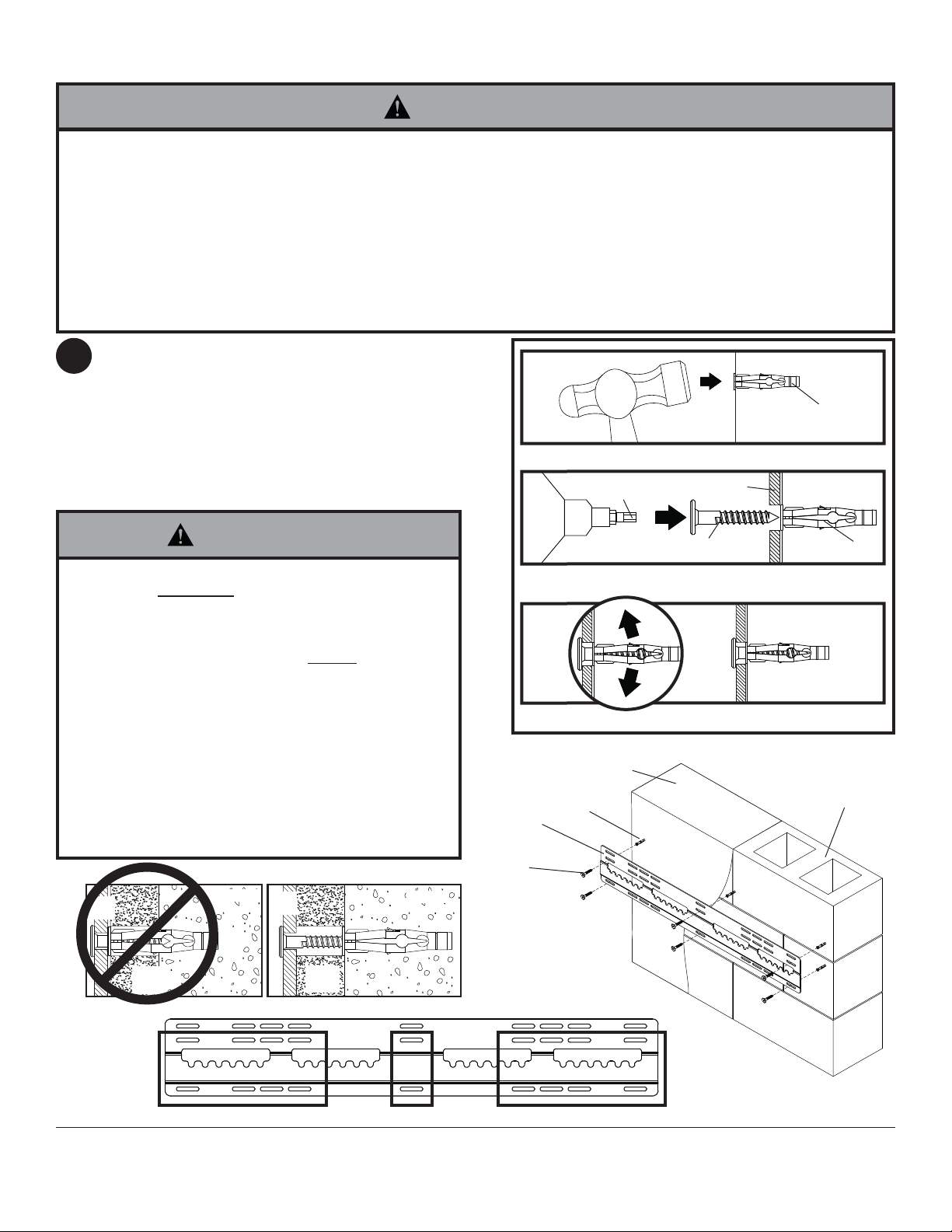
Make sure that wall plate (A) is level, use it as
1
a template to mark six mounting holes. The top
mounting slots should be located X" above the
desired display center as shown in fi gure 1.4 and
1.5 on page 5. Drill six 5/16" (8mm) dia. holes to a
minimum depth of 2.5" (64mm). Insert anchors (D) in
holes fl ush with wall as shown (right). Place wall plate
over anchors and secure with six wood screws (C).
Level, then tighten all fasteners.
1
Drill holes and insert anchors (D).
2
K
A
concrete
surface
D
WARNING
• Tighten screws so that wall plate is fi rmly attached,
but do not overtighten. Overtightening can damage
screws, greatly reducing their holding power.
• Never tighten in excess of 80 in. • lb (9 N.M.).
• Always attach concrete anchors directly to loadbearing concrete.
• Never attach concrete anchors to concrete covered
with plaster, drywall, or other fi nishing material.
If mounting to concrete surfaces covered with a
fi nishing surface is unavoidable (not evaluated by
UL), the fi nishing surface must be counterbored
as shown below. Be sure concrete anchors do not
pull away from concrete when tightening screws. If
plaster/drywall is thicker than 5/8", custom fasteners
must be supplied by installer (not evaluated by UL).
INCORRECT CORRECT
plate
CUTAWAY VIEW
wall
plaster/
dry wall
concrete
wall
plate
plaster/
dry wall
concrete
C
Place plate (A) over anchors (D) and secure with screws (C).
3
Tighten all fasteners.
SOLID CONCRETE
D
A
C
D
CINDER
BLOCK
DETAIL 1
SEGMENT 1 SEGMENT 2 SEGMENT 3
6 of 29
ISSUED: 04-01-11 SHEET #: 203-9029-2 07-27-11
Page 7
Installing Display Screws
WARNING
• Tighten screws so they are fi rmly attached. Do not tighten with excessive force. Overtightening can cause stress
damage to screws, greatly reducing their holding power and possibly causing screw heads to become detached.
Tighten to 40 in. • lb (4.5 N.M.) maximum torque.
• If screws don't get three complete turns in the display inserts or if screws bottom out and bracket is still not tightly
secured, damage may occur to display or product may fail.
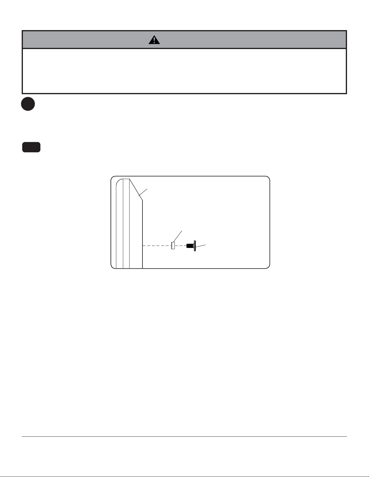
To prevent scratching the display, set a cloth on a fl at, level surface that will support the weight of the display.
2
For Flat Back Display
Place display face side down. If display has knobs on the back, remove them to allow the adapter brackets to be
attached.
NOTE: Top and bottom holes of display must always be used.
Begin with the shortest length screw (E,G, or M) and hand thread through 1/8" spacer (O,P) into display as shown
2-1
in fi gure 2.1. Screw must make at least three full turns into the mounting hole and fi t snug into place. Do not over
tighten. If screw cannot make three full turns into the display, select a longer length screw (F,H, or N) from the
baffl ed fastener pack. Repeat for remaining mounting holes and tighten screws.
DISPLAY
fi g. 2.1
SPACER (O,P)
SCREW (E,G, or M)
7 of 29
ISSUED: 04-01-11 SHEET #: 203-9029-2 07-27-11
Page 8
Mounting Flat Panel Display
WARNING
• Always use an assistant or mechanical lifting equipment to safely lift and position the fl at panel displays.
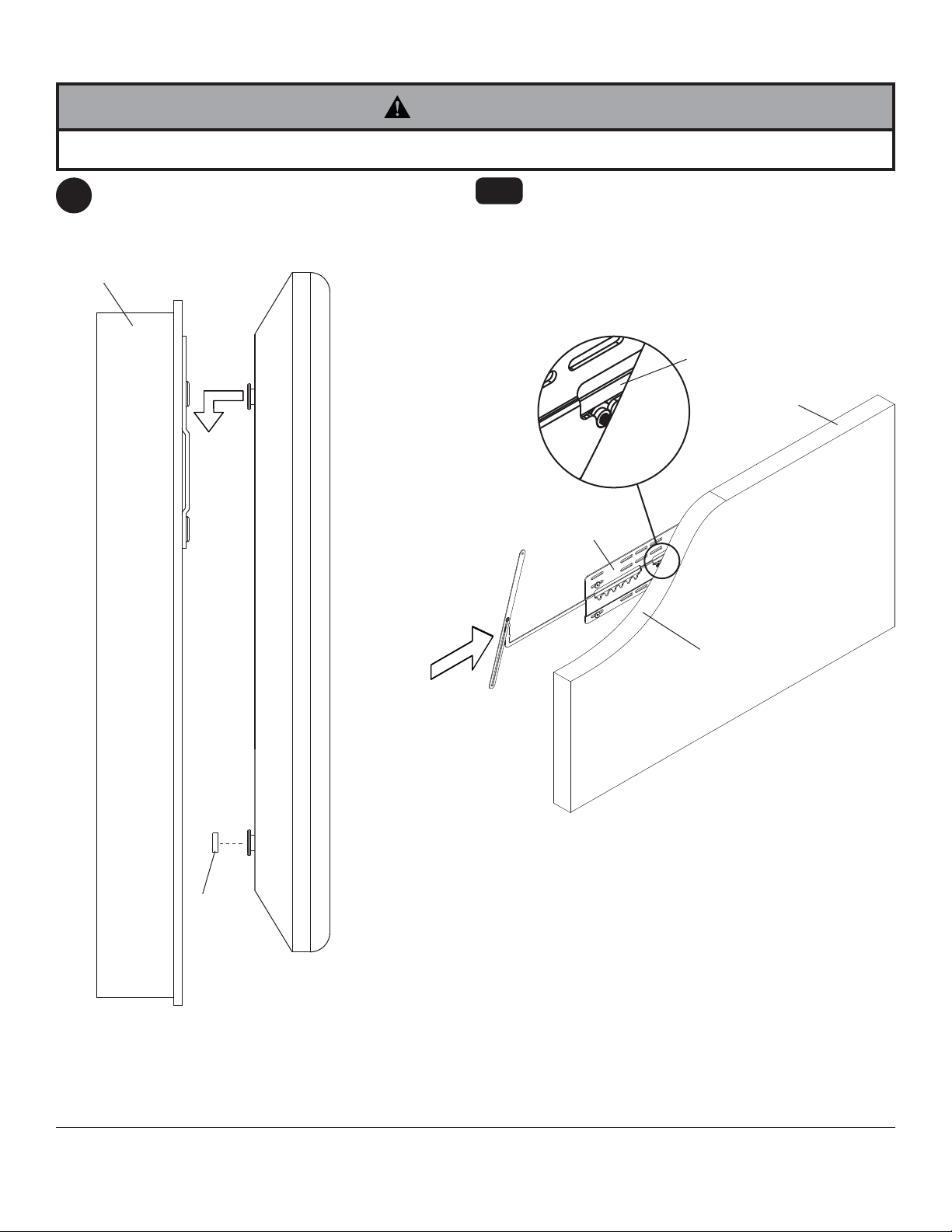
Apply cloth bumpers (Q) to bottom mounting
3
screws as shown in fi gure 3.1.
Hook top mounting screws into wallplate grooves.
WOOD STUD
3-1
B
Secure display by inserting lock arm (B) into wall
plate (A) as shown in fi gure 3.2.
Lock arm must reside over top of display mounting
screws as shown in detail 2.
DETAIL 2
B
DISPLAY
A
Q
CUTAWAY
VIEW
fi g. 3.2
fi g. 3.1
8 of 29
ISSUED: 04-01-11 SHEET #: 203-9029-2 07-27-11
Page 9
OPTIONAL: Securing Locking Arm
CAUTION
• Be careful not to pinch fi ngers when adjusting
locking arm (B).
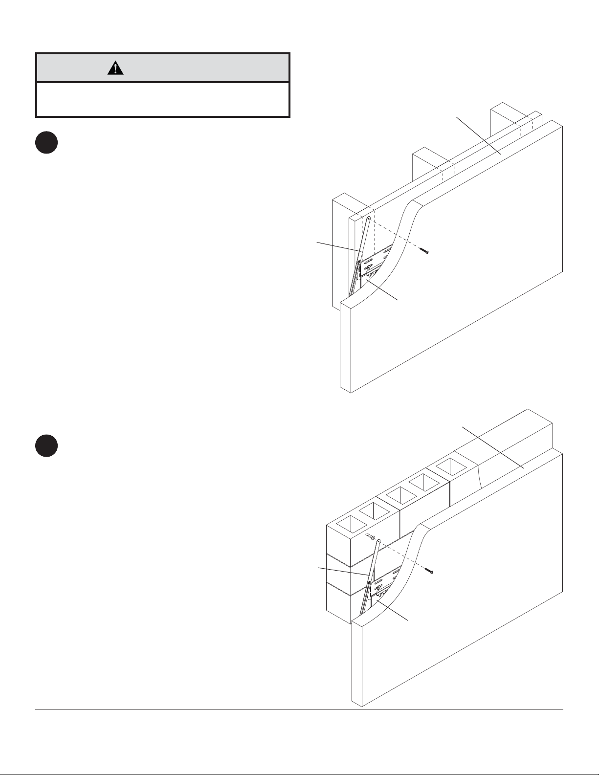
WOOD STUD: Adjust locking arm (B) until it aligns
4
to wood stud and secure using one #10 x 1-1/2"
security wood screw (R). If locking arm is diffi cult
to adjust, spin arm to loosen joint.
DISPLAY
B
R
A
CONCRETE/CINDER BLOCK: Adjust locking arm
4
(B) to desired position, mark center of mounting
hole, and drill one 1/4" (6mm) dia. hole to a
minimum depth of 2". Insert alligator anchor (S)
into hole and secure locking arm (B) with one #10
x 1-1/2" security wood screw (R). If locking arm is
diffi cult to adjust, spin arm to loosen joint.
B
DISPLAY
S
R
A
9 of 29
All other brand and product names are trademarks or registered trademarks of their respective owners.
ISSUED: 04-01-11 SHEET #: 203-9029-2 07-27-11
© 2011, Peerless Industries, Inc. All rights reserved.
Peerless Industries, Inc.
2300 White Oak Circle
Aurora, Il 60502
www.peerlessmounts.com
Page 10
Instalación y ensamblaje:
Soporte Plano Peerless Ultra-Delgado para Pantallas Planas de
37" - 65" (94 - 165 cm)*
Modelo: SUF661
*Requisitos para la compatibilidad de las pantallas
• Es posible que la profundidad del soporte (0.19") no
proporcione sufi ciente espacio para la ventilación
adecuada de algunas pantallas. Por favor, repase los
requisitos del fabricante en relación con la instalación
de la pantalla antes de proceder.
•
La pantalla tiene que tener una superfi cie plana para la
instalación o tiene que tener los agujeros de montaje
en la superfi cie trasera más alejada de la pantalla.
•
La conexión de entrada / salida tiene que tener la
orientación adecuada para acomodar una instalación a
0.19" de la pared.
2300 White Oak Circle • Aurora, Il 60502 • (800) 865-2112 • Fax: (800) 359-6500 • www.peerlessmounts.com
Capacidad máxima de soportar carga por UL:
150 lb (68kg)
PUBLICADO: 04-01-11 HOJA #: 203-9029-2 07-27-11
Page 11

Lea la hoja de instrucciones completa antes de comenzar la instalación y el ensamblaje.
Nota:
Español
ADVERTENCIA
• No comience a instalar su producto de Peerless hasta haber leído y entendido las instrucciones y las advertencias
contenidas en la Hoja de Instalación. Si tiene alguna pregunta acerca de cualquiera de las instrucciones o las advertencias, por favor, llame a Servicio al Cliente de Peerless al 1-800-865-2112 si está en EE. UU. Si es un cliente
internacional, por favor, comuníquese con su distribuidor local.
• Este soporte está diseñado para sostener la pantalla a 0.33" de la pared. Por favor, repase las recomendaciones
del manual de instalación del fabricante con respecto a la distancia necesaria de la pared para evitar el riesgo de
sufrir lesiones o causar daños a la propiedad.
• Este producto sólo debe ser instalado por una persona que tenga una buena aptitud mecánica, que tenga experiencia en construcción básica de edifi cios y que entienda estas instrucciones en su totalidad.
• Asegúrese de que la superfi cie de apoyo sostendrá, con seguridad, la carga combinada del equipo y todos los
fi jadores y componentes.
• Nunca sobrepase la capacidad máxima de soportar carga aceptada por Underwriters Laboratories. Vea la página
10.
• Si va a instalar el producto en una pared con montantes de madera, asegúrese de que los tornillos de montaje
estén anclados en el centro de los montantes. Se recomienda utilizar un localizador de montantes de "borde a
borde".
• Siempre cuente con la ayuda de un asistente o utilice un equipo mecánico de izar para levantar y colocar el equipo
con más seguridad.
• Apriete los tornillos con fi rmeza, pero no en exceso. Apretarlos en exceso puede dañar los artículos y puede disminuir signifi cativamente su fuerza de fi jación.
• Este producto está diseñado para uso en interiores solamente. Utilizar este producto en exteriores podría causar
fallas del producto y lesiones a individuos.
• Este producto fue diseñado para ser instalado en paredes con la siguiente construcción solamente:
CONSTRUCCIÓN DE LA PARED ACCESORIOS NECESARIOS
• Montante de madera Incluido
• Viga de madera Incluido
• Concreto macizo Incluido
• Bloque de hormigón de escorias Incluido
• Montante de metal Comuníquese con un profesional califi cado
• Ladrillo Comuníquese con un profesional califi cado (no evaluados por UL)
• ¿Otra superfi cie o no está seguro? Comuníquese con un profesional califi cado (no evaluados por UL)
(no evaluados por UL)
Herramientas necesarias para el ensamblaje
• localizador de montantes (se recomienda uno de "borde a borde")
• taladro
• broca de 5/32" (4mm)para paredes con montantes de madera
• broca de 5/16" (8mm) y 1/4" (6mm) para
• nivel
concreto macizo o de bloques de hormigón de escorias
Tabla de centenido
Lista de piezas..................................................................................................................................................................... 12
Instalación en una pared con montantes de madera ..................................................................................................... 13,14
Instalación en una pared de concreto macizo o de bloques de hormigón de escorias ....................................................... 15
Instalar los tornillos de la pantalla ....................................................................................................................................... 16
Instalación de la pantalla plana ........................................................................................................................................... 17
11 de 29
PUBLICADO: 04-01-11 HOJA #: 203-9029-2 07-27-11
Page 12

A
r
Antes de comenzar, asegúrese de que su producto contiene todas las piezas que se muestran.
Las piezas pueden verse un poco distintas a la ilustración.
Español
Lista de piezas
Descripción Cant. Nº de pieza
placa de pared
bloqueo del brazo
B
tornillos para madera
C
anclajes para concreto
D
tornillos de cabeza hexagonal M5 x 12 mm
E
tornillos de cabeza hexagonal M5 x 25 mm
F
tornillos de cabeza hexagonal M6 x 12 mm
G
tornillos de cabeza hexagonal M6 x 25 mm
H
arandela de .725"
I
espaciador de 3/4
J
desarmador de seguridad de 4 mm
K
llave allen de seguridad de 4 mm
L
tornillos de cabeza hexagonal M8 x 12 mm
M
tornillos de cabeza hexagonal M8 x 25 mm
N
espaciador de M5 x 1/8"
O
espaciador de M6 x 1/8"
P
paño de parachoques
Q
tornillos para madera de seguridad
R
anclaje alligato
S
®
C
D
1 046-P1202
1 046-P1212
6 500-1090
6 590-0320
4
4
4
4
4
4
1
1
4
4
4
4
2
1
1
560-1732
560-1733
560-1734
560-1735
540-9478
540-1059
560-1133
560-9646
560-1736
560-1737
046-0223
046-0224
570-0051
520-1092
590-0097
A
B
E
K
L
F
G
M
H
12 de 29
I
J
OP
N
QRS
PUBLICADO: 04-01-11 HOJA #: 203-9029-2 07-27-11
Page 13
Instalación en una pared con montantes de madera
Español
ADVERTENCIA
• El instalador tiene que asegurarse de que la superfi cie de apoyo sostendrá, con seguridad, la carga combinada del
equipo y todos los fi jadores y componentes.
• Apriete los tornillos de madera de manera que la placa de pared se fi je fi rmemente, pero no en exceso. Apretarlos
en exceso puede dañar los tornillos y puede disminuir signifi cativamente su fuerza de fi jación.
• Nunca apriete a más de 80 pulg-lb (9 N•m).
• Asegúrese de que los tornillos de montaje estén anclados en el centro del montante. Se recomienda utilizar un
localizador de montantes de "borde a borde".
• Los accesorios para la instalación que se proveen son para fi jar el soporte a montantes de madera a través de
tabique de yeso-cartón o yeso de espesor estándar. Los instaladores son responsables de suministrar los accesorios necesarios para otros tipos de instalaciones (no evaluados por UL).
La placa de pared (A) sólo se debe instalar en dos montantes que tengan una separación de 16", 20" o 24".
1
Utilice un localizador de montantes para localizar los bordes de los montantes. Se recomienda utilizar un
localizador de montantes de "borde a borde". Tomando los bordes como punto de referencia, trace una línea
vertical por el centro de cada montante. Coloque la placa de pared contra la pared para utilizarla como plantilla.
Las ranuras de montaje superiores deben estar ubicados X" por encima del centro de la pantalla deseada
como se muestra en la fi gura 1.1 y 1.2. Nivele la placa y marque el centro de los cuatro agujeros de montaje.
Asegúrese de que los agujeros de montaje estén sobre las líneas que trazó por el centro de los montantes.
Taladre cuatro agujeros de 5/32" (4mm) de diámetro y 2" (51mm) de profundidad. Asegúrese de que la placa de
pared esté nivelada y fíjela utilizando cuatro tornillos para madera (C), como se muestra en la fi gura 1.3.
fi g. 1.1
XXX
XXX
XXX
Y
()
Y = distancia entre agujeros
de montaje de la pantalla
+ 1.75"X =
2
X"
NOTA: Cuando la placa de pared
(A) en dos montantes, no use los
agujeros de montaje central o
exterior agujeros de montaje.
A
C
PANTALLA
fi g. 1.3
fi g. 1.2
Y"
13 de 29
PUBLICADO: 04-01-11 HOJA #: 203-9029-2 07-27-11
Page 14

Instalación en una pared con montantes de madera triples
Español
ADVERTENCIA
• El instalador tiene que asegurarse de que la superfi cie de apoyo sostendrá, con seguridad, la carga combinada del
equipo y todos los fi jadores y componentes.
• Apriete los tornillos de madera de manera que la placa de pared se fi je fi rmemente, pero no en exceso. Apretarlos
en exceso puede dañar los tornillos y puede disminuir signifi cativamente su fuerza de fi jación.
• Nunca apriete a más de 80 pulg-lb (9 N•m).
• Asegúrese de que los tornillos de montaje estén anclados en el centro del montante. Se recomienda utilizar un
localizador de montantes de "borde a borde".
• Los accesorios para la instalación que se proveen son para fi jar el soporte a montantes de madera a través de
tabique de yeso-cartón o yeso de espesor estándar. Los instaladores son responsables de suministrar los accesorios necesarios para otros tipos de instalaciones (no evaluados por UL).
La placa de pared (A) se puede instalar en tres montantes que tengan una separación de 16". Utilice un
1
localizador de montantes para localizar los bordes de los montantes. Se recomienda utilizar un localizador de
montantes de "borde a borde". Tomando los bordes como punto de referencia, trace una línea vertical por el centro
de cada montante. Coloque la placa de pared contra la pared para utilizarla como plantilla. Las ranuras de montaje
superiores deben estar ubicados X" por encima del centro de la pantalla deseada como se muestra en la fi gura
1.4 y 1.5. Nivele la placa y marque el centro de los seis agujeros de montaje. Asegúrese de que los agujeros de
montaje estén sobre las líneas que trazó por el centro de los montantes. Taladre seis agujeros de 5/32" (4mm) de
diámetro y 2" (51mm) de profundidad. Asegúrese de que la placa de pared esté nivelada y fíjela utilizando seis
tornillos para madera (C), como se muestra en la fi gura 1.6.
fi g. 1.4
C
X"
A
PANTALLA
Y
()
Y = distancia entre agujeros
de montaje de la pantalla
+ 1.75"X =
2
fi g. 1.6
fi g. 1.5
Y"
14 de 29
PUBLICADO: 04-01-11 HOJA #: 203-9029-2 07-27-11
Page 15

Instalación en una pared de concreto macizo o
Español
de bloques de hormigón de escorias
ADVERTENCIA
• Cuando vaya a instalar soportes de pared de Peerless en bloques de hormigón de escorias, asegúrese de que cuente con una capa de concreto
de un grosor mínimo de 1-3/8" en el agujero, que pueda usar para los anclajes para concreto. ¡No taladre en juntas de argamasa! Asegúrese de
hacer la instalación en la parte sólida del bloque, por lo general, a un mínimo de 1" del extremo del bloque. Los bloques de hormigón de escorias tienen que cumplir las especifi caciones de la ASTM C-90. Se sugiere utilizar un taladro eléctrico convencional a baja velocidad para hacer el
agujero en vez de un taladro percutor para no perforar el fondo del agujero al entrar en un vacío o una cavidad.
• Dos tornillos para madera (C) debe estar instalado en la placa de pared (A) en cada segmento como se muestra en el detalle 1, o el producto
puede fallar.
• El concreto tiene que tener una densidad mínima de 2,000 psi. Es posible que un concreto de menos densidad no sostenga el anclaje para
concreto.
• Asegúrese de que la superfi cie de apoyo sostendrá, con seguridad, la carga combinada del equipo y todos los fi jadores y componentes.
Asegúrese de que la placa de pared (A) esté nivelada y
1
utilícela como plantilla para marcar cuatro agujeros de
montaje. Las ranuras de montaje superiores deben estar
ubicados X" por encima del centro de la pantalla deseada
como se muestra en la fi gura 1.4 y 1.5 de la pagina 14.
Taladre seis agujeros de 5/16" (8mm) de diámetro a una
profundidad mínima de 2.5" (64mm). Inserte los anclajes
(D) en los agujeros a ras con la pared, como se muestra (a
la derecha). Coloque la placa de pared sobre los anclajes y
fíjela con seis tornillos para madera (C). Nivele y apriete todos
los sujetadores.
ADVERTENCIA
• Apriete los tornillos de manera que la placa de pared se fi je fi rmemente, pero no en exceso. Apretarlos en exceso puede dañar los
tornillos y puede disminuir signifi cativamente su fuerza de fi jación.
• Nunca apriete a más de 80 pulg-lb (9 N•m).
• Siempre fi je los anclajes para concreto directamente en la pared
que sostiene la carga.
• Nunca fi je los anclajes para concreto a una pared de concreto
recubierta con yeso, tabique de yeso-cartón u otro material de
acabado. Si es inevitable hacer la instalación en una superfi cie de
concreto recubierta con una superfi cie de acabado
por UL), la superfi cie de acabado tiene que ser escariada, como se
muestra abajo. Asegúrese de que los anclajes para concreto no se
separen del concreto cuando apriete los tornillos. Si el grosor de la
capa de yeso o tabique de yeso-cartón tiene un grosor mayor de
5/8", el instalador tiene que suministrar las fi jaciones especiales
evaluados por UL).
(no evaluados
1
Taladre los agujeros e inserte los anclajes (D).
2
Coloque la placa (A) sobre los anclajes (D) y fíjela con los
tornillos (C).
3
Apriete todas las fi jaciones.
CONCRETO MACIZO
(no
A
D
K
C
techno de
concreto
D
A
D
BLOQUE DE
HORMIGÓN DE
ESCORIAS
INCORRECTO
placa de
pared
VISTA EN CORTE
yeso / tabique de yeso-cartón
C
concreto
CORRECTO
placa de
pared
yeso / tabique de yeso-cartón
concreto
SEGMENTO 1 SEGMENTO 2 SEGMENTO 3
15 de 29
PUBLICADO: 04-01-11 HOJA #: 203-9029-2 07-27-11
Page 16

Español
Instalar los tornillos de la pantalla
ADVERTENCIA
• Apriete los tornillos de manera que los soportes adaptadores se fi jen con fi rmeza. No los apriete con fuerza
excesiva. Apretar los tornillos en exceso puede causarles daño por forzarlos y puede disminuir signifi cativamente
su fuerza de fi jación y podría causar el desprendimiento de las cabezas de los tornillos. Apriete los tornillos a un
máximo de 40 pulg-lb (4.5 N•m) de par torsor.
• Si no se les da tres vueltas completas a los tornillos en los insertos de la pantalla o si los tornillos topan fondo y el
soporte todavía no está fi rme, se podría dañar la pantalla o el producto podría no funcionar bien.
Para no rayar la pantalla, coloque un trapo sobre una superfi cie plana y nivelada que sostenga el peso de la pan-
2
talla. Coloque la pantalla boca abajo. Si la pantalla tiene perillas en la parte trasera, quíteselas para poder fi jar los
soportes adaptadores.
NOTA: Siempre se tienen que usar los agujeros superiores e inferiores de la pantalla.
Instalación de un televisor que tiene la parte posterior plana
Comience con uno de los tornillos más cortos (E, G o M), enrósquelo, con la mano, a través del espaciador de
2-1
1/8" (O, P) en la pantalla, como se muestra en la fi gura 2.1. El tornillo tiene que dar, por lo menos, tres vueltas
completas dentro del agujero de montaje y debe quedar ajustado en su lugar. No apriete los tornillos en exceso.
Si el tornillo no puede dar tres vueltas completas al entrar en la parte trasera de la pantalla, seleccione uno de
los tornillos más largos (F, H o N) de los sujetadores identifi cados y clasifi cados en las divisiones del empaque
plástico. Siga el mismo procedimiento con los agujeros de montaje restantes y apriete los tornillos.
PANTALLA
fi g. 2.1
ESPACIADOR (O,P)
TORNILLO (E,G, o M)
16 de 29
PUBLICADO: 04-01-11 HOJA #: 203-9029-2 07-27-11
Page 17

Español
Instalación de la pantalla plana
ADVERTENCIA
• Siempre cuente con un asistente o con un equipo mecánico de izar para levantar y colocar el televisor de plasma
con más seguridad.
Coloque los paragolpes de tela (Q) en los tornillos
3
de montaje inferiores, como se muestra en la fi gura
3.1.
Enganche los tornillos de montaje superiores en las
hendiduras de la placa de pared.
MONTANTE
Para fi jar la pantalla una vez la haya colgado en
su lugar, inserte el brazo fi jador (B) en el lado de la
placa de pared, como se muestra en la fi gura 3.2.
Cerciórese de que el brazo fi jador descanse sobre
los tornillos de montaje, como se muestra en el
detalle 2.
DETALLE 2
B
PANTALLA
A
B
Q
fi g. 3.1
17 de 29
VISTA EN
CORTE
fi g. 3.2
PUBLICADO: 04-01-11 HOJA #: 203-9029-2 07-27-11
Page 18

OPCIONAL: Fijar el brazo fi jador
PRECAUCIÓN
• Tenga cuidado de no pincharse los dedos cuando
fi jar el brazo fi jador (B).
MONTANTE DE MADERA: Ajuste el brazo fi jador
4
(B) hasta que se alinee con el montante de
madera y fíjelo con un tornillo de seguridad para
madera de 10 x 1-1/2" (R). Si el el brazo fi jador
es difícil de ajustar, girar el brazo para afl ojar las
articulaciones.
Español
PANTALLA
B
R
A
CONCRETO O BLOQUE DE HORMIGÓN DE
4
ESCORIAS: Ajuste el brazo fi jador (B) en la
posición deseada, marque el centro del agujero
de montaje y taladre un agujero de 1/4" (6mm)
de diámetro a una profundidad mínima de 2".
Inserte el anclaje alligator (S) en el agujero y fi je el
brazo fi jador (B) con un tornillo de seguridad para
madera de 10 x 1-1/2" (R). Si el el brazo fi jador
es difícil de ajustar, girar el brazo para afl ojar las
articulaciones.
B
PANTALLA
S
R
A
18 de 29
Cualesquiera otras marcas y nombres de productos son marcas comerciales o registradas de sus respectivos dueños.
PUBLICADO: 04-01-11 HOJA #: 203-9029-2 07-27-11
© 2011, Peerless Industries, Inc. Todos los derechos reservados.
Peerless Industries, Inc.
2300 White Oak Circle
Aurora, Il 60502
www.peerlessmounts.com
Page 19

Installation et montage:
Support Plat Ultra-Mince Peerless pour Écrans plats
37" - 65" (94 - 165 cm)*
Modèle: SUF661
*Exigences de compatibilité avec l'écran
• La profondeur de ce support (0,19 po) pourrait ne pas
laisser suffi samment d'espace pour permettre une
ventilation adéquate pour certains écrans. Veuillez vous
reporter aux exigences de montage du fabricant avant
d'installer votre écran.
•
L'écran doit avoir une surface de montage plate
ou alors les trous de montage doivent se trouver à
l'extrémité de la surface arrière de l'écran.
•
La connexion entrée/sortie doit être orientée de
manière à permettre l'installation du support à 0,19 po
du mur.
2300 White Oak Circle • Aurora, Il 60502 • (800) 865-2112 • Fax: (800) 359-6500 • www.peerlessmounts.com
Capacité de charge maximale établie par l’UL:
150 lb (68kg)
PUBLIÉ LE : 04-01-11 FEUILLE no : 203-9029-2 07-27-11
Page 20
Français
Remarque : lisez entièrement la fi che d’instructions avant de commencer l’installation et l’assemblage.
AVERTISSEMENT
• Ne commencez pas à installer votre produit Peerless avant d’avoir lu et assimilé les instructions et les
avertissements contenus dans cette fi che d’installation. Pour toute question concernant les instructions ou
les avertissements, veuillez appeler le service à la clientèle de Peerless au 1-800-865-2112; tous les clients
internationaux sont priés de contacter leur distributeur local.
• Ce support est conçu pour fi xer l’écran à 0,33 po du mur. Veuillez vous reporter aux recommandations du guide
d’installation du fabricant pour établir la distance au mur requise afi n d’éviter les risques de blessures ou de
dommages matériels.
• Ce produit doit être installé uniquement par quelqu’un possédant une bonne aptitude à la mécanique, une
expérience de la construction immobilière et ayant bien compris ces instructions.
• Assurez-vous que la surface de support puisse soutenir sans danger la charge totale de l’équipement ainsi que des
pièces et composants qui y sont attachés.
• Ne dépassez jamais la capacité de charge maximum établie par l’UL. Reportez-vous à la page 19.
• Lors d’une installation sur un mur à montants en bois, assurez-vous que les vis de montage sont ancrées au centre
des montants. L’utilisation d’un localisateur de montants « bord à bord » est fortement recommandée.
• Pour lever et positionner l’équipement en toute sécurité, faites-vous toujours aider par une autre personne ou
utilisez un dispositif de levage mécanique.
• Serrez fermement les vis, mais sans excès. Un serrage excessif peut endommager les composants et en réduire
considérablement la capacité de support.
• Ce produit est conçu uniquement pour un usage intérieur. L’utilisation de ce produit à l’extérieur peut causer une
défaillance du produit et des blessures corporelles.
• Ce produit a été conçu uniquement pour une installation sur les types de murs ci-dessous :
TYPE DE MUR PIÈCES DE FIXATION REQUISES
• Montant en bois Incluses
• Poutre en bois Incluses
• Béton plein Incluses
• Bloc de béton de mâchefer Incluses
• Montant métallique Contacter un professionnel qualifi é (non évalué UL)
• Brique Contacter un professionnel qualifi é (non évalué UL)
• Autre, ou vous n’êtes pas sûr ? Contacter un professionnel qualifi é
Outils nécessaires au montage
• localisateur de montants (un localisateur de montants « bord à bord » est recommandé)
• perceuse
• foret de 5/32 po (4mm) pour les murs à montants en bois
• foret de 5/16 po (8mm) et 1/4 po (6mm) pour les murs à block de béton
• niveau
Table des matières
Liste des pièces ................................................................................................................................................................... 21
Installation sur des murs à en bois ................................................................................................................................. 22,23
Installation sur du béton plein/block de béton ..................................................................................................................... 24
Montage des vis de l'écran .................................................................................................................................................. 25
Montage et demontage d'un écran plat ............................................................................................................................... 26
20 sur 29
PUBLIÉ LE : 04-01-11 FEUILLE no : 203-9029-2 07-27-11
Page 21
A
r
Avant de commencer, assurez-vous que toutes les pièces indiquées sont incluses avec le produit.
Il est possible que les pièces semblent légèrement différentes de l’illustration.
Français
Lista de piezas
Descripción Cant. Nº de pieza
placa de pared
bloqueo del brazo
B
tornillos para madera
C
anclajes para concreto
D
tornillos de cabeza hexagonal M5 x 12 mm
E
tornillos de cabeza hexagonal M5 x 25 mm
F
tornillos de cabeza hexagonal M6 x 12 mm
G
tornillos de cabeza hexagonal M6 x 25 mm
H
arandela de .725"
I
espaciador de 3/4
J
desarmador de seguridad de 4 mm
K
llave allen de seguridad de 4 mm
L
tornillos de cabeza hexagonal M8 x 12 mm
M
tornillos de cabeza hexagonal M8 x 25 mm
N
espaciador de M5 x 1/8"
O
espaciador de M6 x 1/8"
P
paño de parachoques
Q
tornillos para madera de seguridad
R
anclaje alligato
S
®
C
D
1 046-P1202
1 046-P1212
6 500-1090
6 590-0320
4
4
4
4
4
4
1
1
4
4
4
4
2
1
1
560-1732
560-1733
560-1734
560-1735
540-9478
540-1059
560-1133
560-9646
560-1736
560-1737
046-0223
046-0224
570-0051
520-1092
590-0097
A
B
E
K
L
F
G
M
H
21 sur 29
I
J
OP
N
QRS
PUBLIÉ LE : 04-01-11 FEUILLE no : 203-9029-2 07-27-11
Page 22

Français
Installation to Double Wood Stud Wall
AVERTISSEMENT
• L’installateur doit s’assurer que la surface de support pourra soutenir sans danger la charge combinée de
l’équipement, de toute sa visserie et de tous ses composants.
• Serrez les vis à bois de manière que la plaque murale soit fermement fi xée, mais sans excès. Un serrage excessif
peut endommager les vis et en réduire considérablement le pouvoir de maintien.
• Ne serrez jamais à plus de 9 Nm (80 po-lb).
• Assurez-vous que les vis de montage sont ancrées au centre des montants. L’usage d’un localisateur de montants
« bord à bord » est fortement conseillé.
• La visserie est fournie pour fi xer la monture à travers une cloison sèche ou du plâtre d’épaisseur standard et
dans des montants en bois. Il appartient aux installateurs de fournir la visserie nécessaire pour d’autres types de
situations (non évalué UL).
La plaque murale (A) doit être installée uniquement à deux montants espacés de 16 po, 20 po ou 24 po. Repérez
1
le bord des montants à l’aide d’un localisateur de montants. L’utilisation d’un localisateur de montants « bord à
bord » est fortement recommandée. Après avoir repéré les bords, tracez une ligne verticale le long du centre
de chaque montant. Posez la plaque murale sur le mur et utilisez-la comme gabarit. Les fentes de montage
supérieures doivent être situées X po au-dessus du centre d'exposition, comme illustré à la fi gure 1.1 et 1.2.
Mettez la plaque à niveau et marquez le centre des quatre trous de fi xation. Veillez à ce que les trous de fi xation
soient sur la ligne médiane du montant. Percez quatre trous de 5/32 po (4 mm) de dia. et de 2 po (51mm) de
profondeur. Veillez à ce que la plaque murale soit de niveau et fi xez-la à l’aide de quatre vis à bois (C) comme
illustré à la fi gure 1.3.
fi g. 1.1
XXX
XXX
XXX
Y
()
Y = écart entre l'affi chage
des trous de montage
+ 1.75"X =
2
X"
ÉCRAN
fi g. 1.2
Y"
REMARQUE: Lorsque la
plaque de montage mural
(A) à deux montants,
ne pas utiliser le centre
des trous de montage
ou de trous de montage
extérieurs.
A
C
22 sur 29
fi g. 1.3
PUBLIÉ LE : 04-01-11 FEUILLE no : 203-9029-2 07-27-11
Page 23

Français
Installation sur un mur à triples montants en bois
AVERTISSEMENT
• L’installateur doit s’assurer que la surface de support pourra soutenir sans danger la charge combinée de
l’équipement, de toute sa visserie et de tous ses composants.
• Serrez les vis à bois de manière que la plaque murale soit fermement fi xée, mais sans excès. Un serrage excessif
peut endommager les vis et en réduire considérablement le pouvoir de maintien.
• Ne serrez jamais à plus de 9 Nm (80 po-lb).
• Assurez-vous que les vis de montage sont ancrées au centre des montants. L’usage d’un localisateur de montants
« bord à bord » est fortement conseillé.
• La visserie est fournie pour fi xer la monture à travers une cloison sèche ou du plâtre d’épaisseur standard et
dans des montants en bois. Il appartient aux installateurs de fournir la visserie nécessaire pour d’autres types de
situations (non évalué UL).
La plaque murale (A) peut être installée sur trois montants espacés de 16 po. Repérez le bord des montants
1
à l’aide d’un localisateur de montants. L’utilisation d’un localisateur de montants « bord à bord » est fortement
recommandée. Après avoir repéré les bords, tracez une ligne verticale le long du centre de chaque montant. Posez
la plaque murale sur le mur et utilisez-la comme gabarit. Les fentes de montage supérieures doivent être situées X
po au-dessus du centre d'exposition, comme illustré à la fi gure 1.4 et 1.5. Mettez la plaque à niveau et marquez le
centre des six trous de fi xation. Veillez à ce que les trous de fi xation soient sur la ligne médiane du montant. Percez
six trous de 5/32 po (4mm) de dia. et de 2 po (51mm) de profondeur. Veillez à ce que la plaque murale soit de
niveau et fi xez-la à l’aide de six vis à bois (C) comme illustré à la fi gure 1.6.
fi g. 1.4
C
X"
A
ÉCRAN
Y
()
Y = écart entre l'affi chage
des trous de montage
+ 1.75"X =
2
fi g. 1.6
fi g. 1.5
Y"
23 sur 29
PUBLIÉ LE : 04-01-11 FEUILLE no : 203-9029-2 07-27-11
Page 24

Installation sur du béton plein/block de béton
Français
AVERTISSEMENT
• Si vous installez des montures murales Peerless sur un bloc de béton de mâchefer, vérifi ez que vous disposez d’une épaisseur de béton d’au
moins 0,34 cm (1 3/8 po) dans le trou destiné aux ancrages de béton. Ne percez pas dans les joints de mortier ! Veillez à effectuer le montage
dans une partie pleine du bloc, généralement à au moins 2,5 cm (1 po) du côté du bloc. Le bloc de béton de mâchefer doit être conforme aux
spécifi cations de l’ASTM C-90. Pour percer le trou, il est conseillé d’utiliser une perceuse électrique standard sur un réglage bas au lieu d’un
marteau perforateur, afi n d’éviter de briser la partie arrière du trou lorsque vous pénétrez un vide ou une cavité.
• Vis à bois deux (C) doit être installé dans la plaque murale (A) dans chaque segment tel que montré dans le détail 1, ou le produit détérioré.
• Le béton doit avoir une densité minimale de 2000 psi. Un béton de densité moindre risquerait de ne pas retenir un ancrage de béton.
• Assurez-vous que la surface de support pourra soutenir sans danger la charge combinée de l’équipement, de toute sa visserie et de tous ses
composants.
Assurez-vous que la plaque murale (A) est de
1
niveau et utilisez-la comme gabarit pour marquer
l’emplacement des six trous de fi xation. Les fentes
de montage supérieures doivent être situées X po
au-dessus du centre d'exposition, comme illustré à la
fi gure 1.4 et 1.5 en page 23. Percez six trous de 5/16
po (8mm) de dia. à une profondeur minimale de 2,5
po (64mm). Insérez les chevilles d’ancrage (D) dans
les trous au ras du mur comme illustré (à droite).
Posez la plaque murale sur les chevilles d’ancrage
et fi xez-la à l’aide de six vis à bois (C). Assurez-vous
qu'elle est de niveau, puis serrez toutes les fi xations.
AVERTISSEMENT
• Serrez les vis de manière que la plaque murale soit fermement
fi xée, mais sans excès. Un serrage excessif peut endommager
les vis et en réduire considérablement le pouvoir de maintien.
• Ne serrez jamais à plus de 9 Nm (80 po-lb).
• Fixez toujours des ancrages de béton directement sur du béton
porteur.
• Ne fi xez jamais d’ancrages sur du béton recouvert de plâtre, une
cloison sèche ou autre matériau de fi nition. Si vous ne pouvez
pas éviter d’effectuer le montage sur du béton recouvert d’une
surface de fi nition (non évalué UL), celle-ci doit être chambrée,
comme indiqué ci-dessous. Assurez-vous que les ancrages de
béton ne se séparent pas du béton lorsque vous serrez les vis.
Si l’épaisseur du plâtre / de la cloison sèche dépasse 1,5 cm (5/8
po), des fi xations adaptées devront être fournies par l’installateur
(non évalué UL).
1
Percez des trous et insérez les ancrages (D).
2
K
A
surface en béton
C
Placez la plaque (A) sur les ancrages (D) et fi xez avec
des vis (C).
3
Serrez toutes les fi xations.
BÉTON PLEIN
BLOC DE BÉTON
DE MÂCHEFER
D
A
D
D
INCORRECT
plaque
murale
VUE EN COUPE
DÉTAIL 1
plâtre / cloison sèche
SEGMENT 1 SEGMENT 2 SEGMENT 3
béton
plaque
murale
CORRECT
plâtre / cloison sèche
béton
24 sur 29
C
PUBLIÉ LE : 04-01-11 FEUILLE no : 203-9029-2 07-27-11
Page 25

Français
Montage des vis de l'écran
AVERTISSEMENT
• Serrez les vis de manière à fi xer solidement les supports adaptateurs. N’employez pas une force excessive pour ce
faire. Un serrage excessif peut causer des contraintes risquant d’endommager les vis, de réduire considérablement
leur pouvoir de maintien et d’en détacher les têtes. Serrez les vis à un couple maximum de 4,5 Nm (40 po-lb).
• Si les vis ne sont pas enfoncées de trois tours complets dans les inserts ou si elles sont serrées au maximum sans
parvenir à maintenir solidement le support, l’écran peut être abîmé ou le produit détérioré.
Afi n d’éviter de rayer l’écran, posez un morceau de tissu sur une surface plane et de niveau qui peut supporter le
2
poids de l’écran. Posez l’écran à plat, tourné vers le bas. Si l’écran possède des boutons à l’arrière, enlevez-les
pour pouvoir fi xer les supports adaptateurs.
REMARQUE : Les trous supérieurs et inférieurs de l’écran doivent toujours être utilisés.
Pour les écrans à dos plat
Commencez par la vis la plus courte (E, G ou M) et vissez-la à la main dans l’entretoise de 1/8 po (O, P) puis
2-1
dans l’écran, comme illustré à la fi gure 2.1. La vis doit effectuer au moins trois tours complets dans le trou de
fi xation et tenir solidement en place. Ne pas trop serrer. S’il est impossible d’effectuer trois tours de vis complets,
choisissez une vis plus longue (F, H ou N) dans le jeu de fi xations à compartiments. Répétez pour le reste des
trous de fi xation et resserrez les vis.
ÉCRAN
fi g. 2.1
ENTRETOISE (O,P)
VIS (E,G, ou M)
25 sur 29
PUBLIÉ LE : 04-01-11 FEUILLE no : 203-9029-2 07-27-11
Page 26

Montage d'un écran plat
AVERTISSEMENT
• Pour lever et positionner l’écran plasma en toute sécurité, faites-vous toujours aider par une autre personne ou
utilisez un matériel de levage mécanique.
Français
Posez les protecteurs en tissu (Q) sur les vis de
3
montage inférieures comme illustré à la fi gure 3.1.
Accrochez les vis de montage supérieures aux
rainures de la plaque murale.
MONTANTS
Afi n de faire tenir l’écran en place une fois accroché,
insérez le bras de verrouillage (B) dans le côté de
la plaque murale comme illustré à la fi gure 3.2.
Veillez à ce que le bras de verrouillage repose sur le
dessus des vis de montage comme illustré dans le
dessin de détail 2.
DÉTAIL 2
B
ÉCRAN
A
B
Q
fi g. 3.1
26 sur 29
VUE EN
COUPE
fi g. 3.2
PUBLIÉ LE : 04-01-11 FEUILLE no : 203-9029-2 07-27-11
Page 27

FACULTATIF : Fixation du bras de verrouillage
ATTENTION
• Prenez garde à ne pas vous pincer les doigts en le
fi xation du bras de verrouillage (B).
MONTANT EN BOIS : Réglez le bras de
4
verrouillage (B) jusqu’à ce qu’il soit aligné avec
le montant en bois et fi xez-le à l’aide d'une vis à
bois de sécurité no 10 x 1-1/2 po (R). Si le bras
de verrouillage est diffi cile à régler, le spin du bras
pour desserrer commune.
B
Français
ÉCRAN
R
A
BÉTON/BLOC DE BÉTON : Réglez le bras
4
de verrouillage (B) dans la position souhaitée,
marquez le centre du trou de fi xation et percez
un trou de 1/4 po (6mm) de dia. à une profondeur
minimale de 2 po. Insérez l’ancrage alligator (S)
dans le trou et fi xez le bras de verrouillage (B) à
l’aide d'une vis à bois de sécurité no 10 x 1-1/2 po
(R). Si le bras de verrouillage est diffi cile à régler,
le spin du bras pour desserrer commune.
B
ÉCRAN
S
R
A
27 sur 29
Tous les autres noms de marques et de produits sont des marques de commerce ou déposées de leurs propriétaires respectifs.
PUBLIÉ LE : 04-01-11 FEUILLE no : 203-9029-2 07-27-11
© 2011, Peerless Industries, Inc. Tous droits réservés.
Peerless Industries, Inc.
2300 White Oak Circle
Aurora, Il 60502
www.peerlessmounts.com
Page 28
LIMITED FIVE-YEAR WARRANTY
Peerless Industries, Inc. (“Peerless”) warrants to original end-users of Peerless® products will be free from defects in material and workmanship, under normal
use, for a period of fi ve years from the date of purchase by the original end-user (but in no case longer than six years after the date of the product’s manufacture).
In no event shall the duration of any implied warranty of merchantability or fi tness for a particular purpose be longer than the period of the applicable
express warranty set forth above. Some states do not allow limitations on how long an implied warranty lasts, so the above limitation may not apply to you.
This warranty does not cover damage caused by (a) service or repairs by the customer or a person who is not authorized for such service or repairs by Peerless,
(b) the failure to utilize proper packing when returning the product, (c) incorrect installation or the failure to follow Peerless’ instructions or warnings when installing,
In no event shall Peerless be liable for incidental or consequential damages or damages arising from the theft of any product, whether or not secured
by a security device which may be included with the Peerless® product. Some states do not allow the exclusion or limitation of incidental or consequential
This warranty is in lieu of all other warranties, expressed or implied, and is the sole remedy with respect to product defects. No dealer, distributor, installer or other
person is authorized to modify or extend this Limited Warranty or impose any obligation on Peerless in connection with the sale of any Peerless® product.
At its option, Peerless will repair or replace, or refund the purchase price of, any product which fails to conform with this warranty.
using or storing the product, or (d) misuse or accident, in transit or otherwise, including in cases of third party actions and force majeure.
damages, so the above limitation or exclusion may not apply to you.
This warranty gives specifi c legal rights, and you may also have other rights which vary from state to state.
www.peerlessmounts.com
© 2011 Peerless Industries, Inc.
Español
GARANTÍA LIMITADA DE CINCO AÑOS
Peerless Industries, Inc. (Peerless) les garantiza a los usuarios fi nales originales de los productos Peerless® que los productos Peerless® estarán libres de
defectos de materiales o de manufactura, en condiciones de uso normal, durante un periodo de cinco (5) años a partir de la fecha en la que el usuario fi nal
original compre cualquier producto (pero, en ningún caso, durante un periodo mayor de 6 años después de la fecha de manufactura del producto). Queda a la
La duración de toda garantía implícita de comerciabilidad o de idoneidad para un propósito en particular no sobrepasará en caso alguno el periodo
de vigencia de la garantía explícita correspondiente indica en lo anterior. Algunos Estados no permiten que se establezcan limitaciones en relación con el
Esta garantía no cubre daños causados por (a) trabajos de mantenimiento o de reparación hechos por el cliente o alguna persona que no esté autorizada por
Peerless para realizar dichos trabajos de mantenimiento o de reparación, (b) no empacar el producto como es debido si lo devuelve, (c) hacer una instalación
incorrecta o no seguir las instrucciones o las advertencias de Peerless al instalar, utilizar o guardar el producto o (d) el mal uso o los accidentes, en tránsito o en
Peerless no tendrá responsabilidad en ningún caso de daños y perjuicios incidentales o indirectos o de daños y perjuicios que surjan por el robo de
cualquier producto, ya sea que el mismo esté o no esté asegurado con un dispositivo de seguridad que se haya incluido con el producto de Peerless®.
Algunos Estados no permiten que se excluyan o se establezcan limitaciones en relación con los daños y perjuicios incidentales o indirectos, de manera que es
Esta garantía remplaza toda otra garantía, expresa o implícita, y es el único recurso en lo que respecta a los defectos del producto. Ningún concesionario,
distribuidor, instalador ni ninguna otra persona está autorizada a modifi car o extender esta Garantía Limitada ni a imponer obligación alguna a Peerless en
Esta garantía concede derechos específi cos creados por ley y es posible que usted, además, tenga otros derechos que varían de acuerdo con el Estado donde
discreción de Peerless, reparar, reemplazar o rembolsar el precio de compra de cualquier producto que no cumpla esta garantía.
periodo de duración de una garantía implícita, de manera que es posible que la limitación expuesta en lo anterior no sea pertinente a usted.
otras circunstancias, incluidos los casos relacionados con las acciones de terceros o una fuerza mayor.
posible que la limitación o la exclusión expuesta en lo anterior no sea pertinente a usted.
relación con la venta de cualquier producto de Peerless®.
se encuentre.
www.peerlessmounts.com
28 of 29
© 2011 Peerless Industries, Inc.
ISSUED: 04-01-11 SHEET #: 203-9029-2 07-27-11
Page 29

Français
GARANTIE DE CINQ ANS
Peerless Industries, Inc. (« Peerless ») garantit aux utilisateurs fi naux d’origine des produits PeerlessMD que lesdits produits ne présenteront aucun défaut de
matériau ou de main-d’œuvre, dans la mesure où ils sont utilisés normalement, pendant une période de cinq ans à compter de la date d’achat par l’utilisateur fi nal
d’origine (mais en aucun cas plus de six ans après la date de fabrication du produit). Peerless, à sa discrétion, réparera ou remplacera tout produit non conforme
La durée de toute garantie implicite de qualité commerciale ou d’application à un usage particulier n’excédera en aucun cas la durée de la garantie
applicable expressément stipulée plus haut. Certains états ou provinces n’autorisent pas la limitation de la durée d’une garantie implicite, et la limitation ci-
Cette garantie ne couvre pas les dommages causés par (a) un entretien ou des réparations effectués par l’acheteur ou une personne non autorisée par Peerless
à effectuer un tel entretien ou de telles réparations, (b) un emballage inadéquat lors de l’expédition d’un produit retourné, (c) une installation incorrecte ou le non-
respect des instructions ou mises en garde de Peerless lors de l’installation, l’utilisation ou le rangement du produit, ou (d) une mauvaise utilisation ou un accident
survenu lors d’un transport ou autrement, y compris l’intervention de tiers et les cas de force majeure.
Peerless ne peut en aucun cas être tenu responsable de quelque dommage accessoire ou indirect que ce soit ni de dommages résultant du vol
d’un quelconque produit, que celui-ci ait été ou non protégé par un dispositif de sécurité intégré à un produit Peerless
n’autorisent pas l’exclusion ou la restriction des dommages accessoires ou indirects, et il est possible que les restrictions ou exclusions ci-dessus ne s’appliquent
Les dispositions de cette garantie remplacent toute autre garantie expresse ou implicite et constituent le seul recours possible en cas de défectuosité d’un
produit. Aucun marchand, distributeur, installateur ou autre personne n’est autorisé à modifi er ou étendre la portée de cette garantie limitée, ni à imposer quelque
obligation ce que soit à Peerless en ce qui concerne la vente de tout produit Peerless
Cette garantie offre des droits juridiques particuliers auxquels peuvent s’ajouter d’autres droits, susceptibles de varier d’une province ou d’un état à l’autre.
aux termes de cette garantie, ou en remboursera le prix d’achat.
dessus peut donc ne pas vous être applicable.
pas à votre cas.
MD
. Certains états ou provinces
MD
.
www.peerlessmounts.com
© 2011 Peerless Industries, Inc.
29 of 29
ISSUED: 04-01-11 SHEET #: 203-9029-2 07-27-11
 Loading...