

Page 1
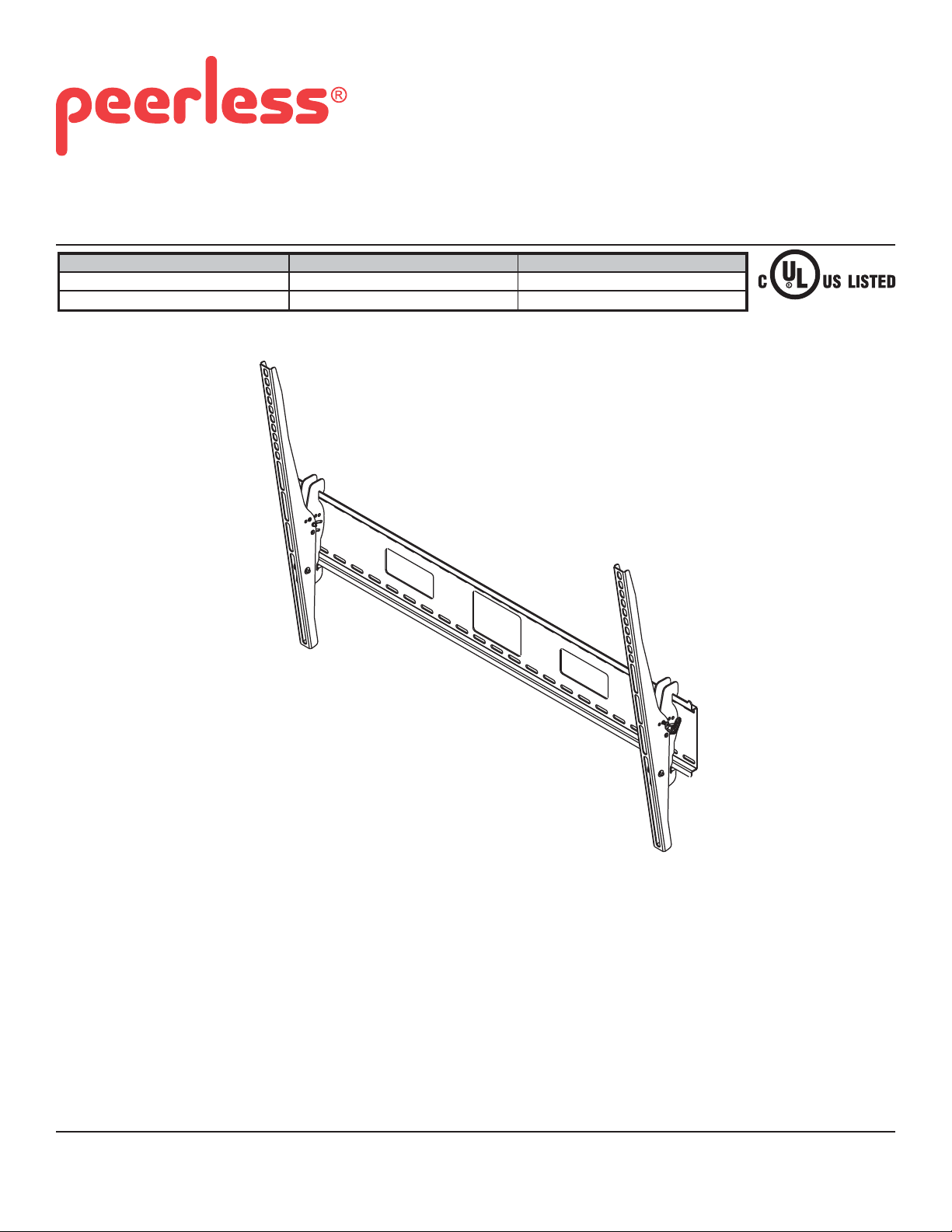
Installation and Assembly: Medical Antimicrobial Universal
Tilt Wall Mount for Flat Panel Displays
Model # Screen Size Range Max. UL Load Capacity
ST670-AB, ST670-AW 42" - 71" (107 - 180 cm) 250 lb (113kg)
ST680-AB, ST680-AW 61" - 102" (155 - 259 cm)
350 lb (159kg)
Features:
• Display held only 3.04" (77mm) from wall for a discreet installation
• Wall plate design allows for wall acces allowing multiple cable management options
• Universal tilt brackets easily hook onto wall plate for fast installation
• Adjustable up to 15° of forward tilt and up to -5° backward tilt for optimal viewing angle
• Pre-tensioned universal tilt bracket allows for tilt angle adjustment in one easy motion.
• Easy grip handle locks the display position into place
• Optional IncreLok™ feature offers fi xed tilts at -5°, 0°, 5°, 10° and 15° increments
• Includes Sorted-For-You™ fastener pack for installation to wood studs, concrete, and cinder block
• Optional horizontal adjustment of up to 8" (203mm) (depending on display model) for perfect display placement
• Treated with Agion
®
medical antimicrobial fi nish in black or white designed to assist with infection control.
2300 White Oak Circle • Aurora, Il 60502 • (800) 865-2112 • Fax: (800) 359-6500 • www.peerlessmounts.com
ISSUED: 09-30-11 SHEET #: 203-9051-1
Page 2
NOTE: Read entire instruction sheet before you start installation and assembly.
WARNING
• Do not begin to install your Peerless product until you have read and understood the instructions and warnings
contained in this Installation Sheet. If you have any questions regarding any of the instructions or warnings, for US
customers please call Peerless customer care at 1-800-865-2112, for all international customers, please contact
your local distributor.
• This product should only be installed by someone of good mechanical aptitude, has experience with basic building
construction, and fully understands these instructions.
• Make sure that the supporting surface will safely support the combined load of the equipment and all attached
hardware and components.
• Never exceed the Maximum Load Capacity. See page one.
• If mounting to wood wall studs, make sure that mounting screws are anchored into the center of the studs. Use of
an "edge to edge" stud fi nder is highly recommended.
• Always use an assistant or mechanical lifting equipment to safely lift and position equipment.
• Tighten screws fi rmly, but do not overtighten. Overtightening can damage the items, greatly reducing their holding
power.
• This product is intended for indoor use only. Use of this product outdoors could lead to product failure and personal
injury.
• This product was designed to be installed on the following wall construction only;
WALL CONSTRUCTION HARDWARE REQUIRED
• Wood Stud Included
• Wood Beam Included
• Solid Concrete Included
• Cinder Block Included
• Metal Stud Do not attach except with Peerless Metal Stud Accessory Kit - ACC615;
(not evaluated by UL)
• Brick Contact Qualifi ed Professional (not evaluated by UL)
• Other or unsure? Contact Qualifi ed Professional (not evaluated by UL)
Tools Needed for Assembly
• stud fi nder ("edge to edge" stud fi nder is recommended)
• phillips screwdriver
• drill
• 5/16" (8mm) bit for concrete and cinder block wall
• 5/32" (4mm) bit for wood stud wall
• level
Table of Contents
Parts List.................................................................................................................................................................................3
Installation to Triple Wood Stud Wall ......................................................................................................................................5
Installation to Solid Concrete or Cinder Block ........................................................................................................................6
Installing Adapter Brackets .....................................................................................................................................................7
Installing Flat Panel Display to Wall Plate ..............................................................................................................................9
Recommended Cleaning Guidelines ................................................................................................................................... 10
2 of 32
ISSUED: 09-30-11 SHEET #: 203-9051-1
Page 3
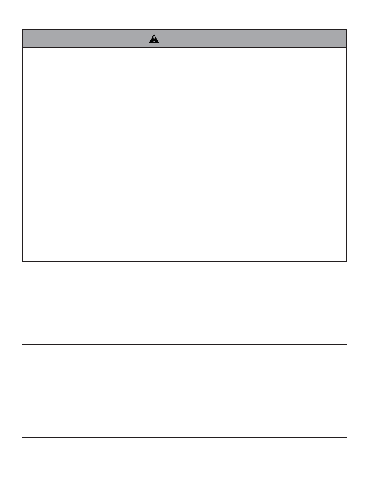
Before you begin, be sure all parts shown are included with your product.
ST670-AB
ST670-AW
Parts may appear slightly different than illustrated.
Parts List
Description Qty.
AAwall plate 1 200-S1901 200-S2901
BB left tilt bracket 1 201-S1474 201-S2474
CC right tilt bracket 1 201-S1476 201-S2476
DD #14 x 2.5" wood screw 6 5S1-015-C03 5S1-015-C03
EE concrete anchor 6 590-0320 590-0320
FF 4 mm allen wrench 1 560-1727 560-1727
GG M10 x 15 mm screw (SF680 only) 4 520-9263 520-9263
HH Washer (SF680 only) 6 5W1-035-X01 5W1-035-X01
II M10 x 2" Penta-pin™ (SF680 only) 1 520-9260 520-9260
ST680-AB
200-S1902 200-S2902
201-S1478 201-S2478
201-S1480 201-S2480
ST680-AW
BB
AA
CC
DD
EE
FF
GG HH
II
3 of 32
ISSUED: 09-30-11 SHEET #: 203-9051-1
Page 4
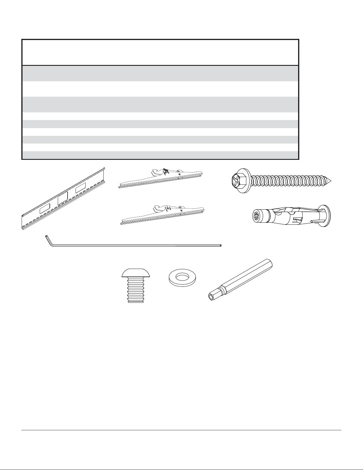
Security Tilt Bracket Fasteners
M4 x 12mm (6)
(510-1079)
M8 x 40mm (4)
(520-1152)
M4 x 25mm (4)
(510-1082)
M6 x 30mm (4)
(520-1067)
M5 x 12mm (4)
(520-1064)
M6 x 20mm (4)
(520-9554)
M5 x 25mm (4)
(520-1122)
M8 x 25mm (4)
(520-1101)
M6 x 12mm (4)
(520-1050)
.5" spacer (4)
(540-1057)
M8 x 15mm (6)
(520-1068)
M6 x 25mm (4)
(520-1211)
multi-washer (6)
(580-1036)
.75" spacer (4)
(540-1059)
4 of 32
ISSUED: 09-30-11 SHEET #: 203-9051-1
Page 5
Installation to Triple Wood Stud Wall
WARNING
• Installer must verify that the supporting surface will safely support the combined load of the equipment and all
attached hardware and components.
• Tighten wood screws so that wall plate is fi rmly attached, but do not overtighten. Overtightening can damage the
screws, greatly reducing their holding power.
• Never tighten in excess of 80 in. • lb (9 N.M.).
• Make sure that mounting screws are anchored into the center of the stud. The use of an "edge to edge" stud fi nder
is highly recommended.
• Two wood screws (DD) must be installed into wall plate (AA) in each segment as shown in detail 1, or product may
fail.
• Hardware provided is for attachment of mount through standard thickness drywall or plaster into wood studs.
Installers are responsible to provide hardware for other types of mounting situations (not evaluated by UL).
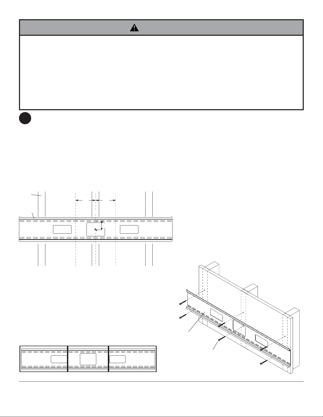
Wall plate (AA) can be mounted to three studs that are 16" (41 cm) apart. Use a stud fi nder to locate the edges of
1
the studs. Use of an edge-to-edge stud fi nder is highly recommended. Based on their edges, draw a vertical line
down each stud’s center. Place wall plate on wall as a template. For ST670 models the top mounting slots should
be 2.9" (74mm) above the desired display center as shown in fi gure 1.1. For ST680 models the top mounting slot
should be 1.3" below the desired display center. Level plate, and mark the center of the six mounting holes. Make
sure that the mounting holes are on the stud centerlines. Drill six 5/32" (4mm) dia. holes 2.5" (64mm) deep. Make
sure that the wall plate is level, secure it using six #14 x 2.5" wood screws (DD) as shown in fi gure 1.2.
Skip to step 2.
NOTE: Wall plate may be mounted up to 6" (152mm) off center as shown in fi gure 1.1.
STUD
6"
(152 mm)
AA
CS = center of display
CS
DETAIL 1
6"
(152 mm)
"X"
fi g. 1.1
AA
SEGMENT 1 SEGMENT 2 SEGMENT 3
5 of 32
DD
fi g. 1.2
ISSUED: 09-30-11 SHEET #: 203-9051-1
Page 6
Installation to Solid Concrete or Cinder Block
WARNING
• When installing Peerless wall mounts on cinder block, verify that you have a minimum of 1-3/8" (35mm) of actual concrete
thickness in the hole to be used for the concrete anchors. Do not drill into mortar joints! Be sure to mount in a solid part of
the block, generally 1" (25mm) minimum from the side of the block. Cinder block must meet ASTM C-90 specifi cations. It is
suggested that a standard electric drill on slow setting is used to drill the hole instead of a hammer drill to avoid breaking out the
back of the hole when entering a void or cavity.
• Two wood screws (DD) must be installed into wall plate (AA) in each segment as shown in detail 1, or product may fail.
• Concrete must be 2000 psi density minimum. Lighter density concrete may not hold concrete anchor.
• Make sure that the wall will safely support four times the combined load of the equipment and all attached hardware and
components.
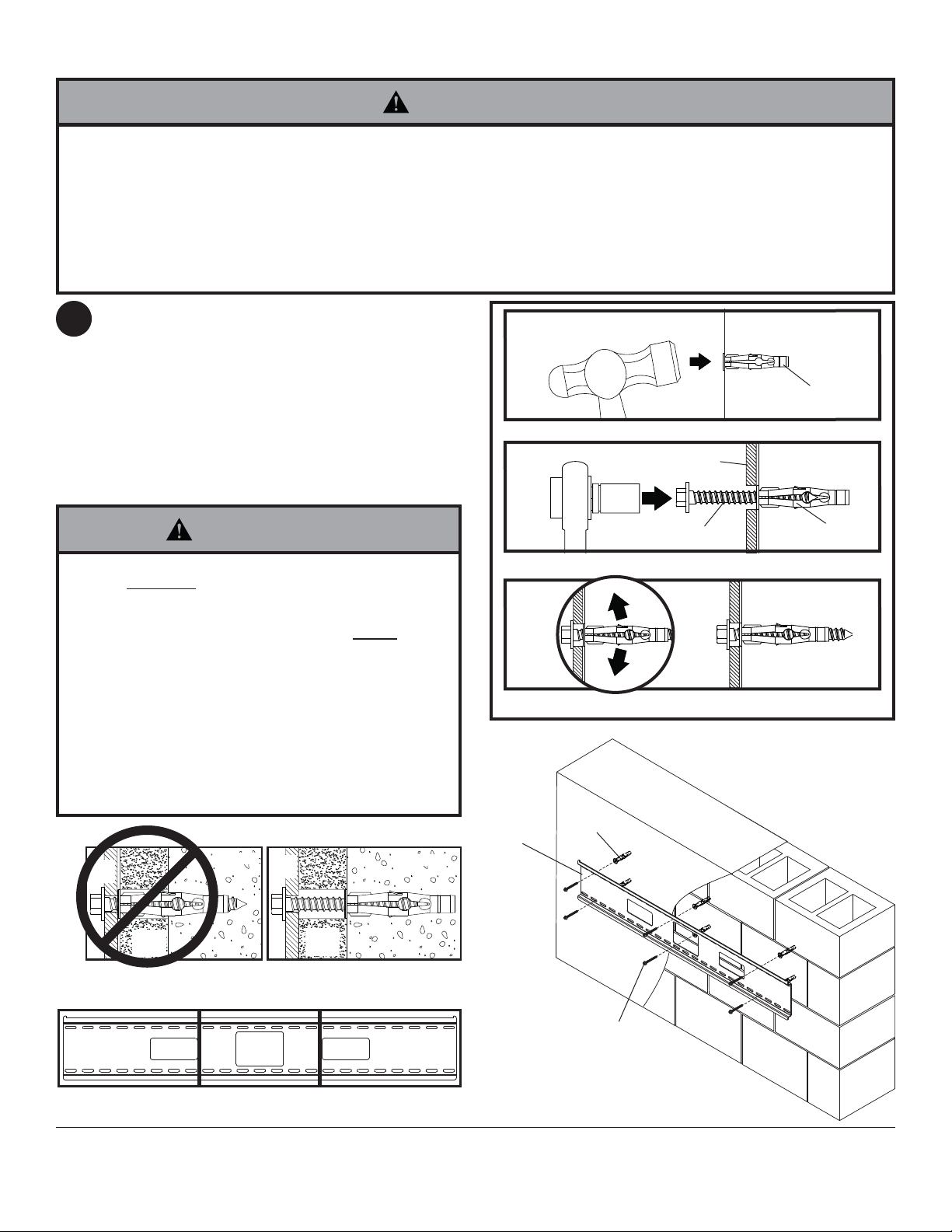
Make sure that wall plate (AA) is level, use it as a
1
template to mark six mounting holes. For ST670
models the top mounting slots should be 2.9"
(74mm) above the desired display center as shown
in fi gure 1.1 on page 5. For ST680 models the top
mounting slot should be 1.3" below the desired
display center. Drill six 5/16" (8mm) dia. holes to
a minimum depth of 2.5" (64mm). Insert anchors
(EE) in holes fl ush with wall as shown (right). Place
wall plate over anchors and secure with #14 x 2.5"
screws (DD). Level, then tighten all fasteners.
WARNING
• Tighten screws so that wall plate is fi rmly attached, but
do not overtighten. Overtightening can damage screws,
greatly reducing their holding power.
• Never tighten in excess of 80 in. • lb (9 N.M.).
• Always attach concrete expansion anchors directly to loadbearing concrete.
• Never attach concrete expansion anchors to concrete
covered with plaster, drywall, or other fi nishing material.
If mounting to concrete surfaces covered with a fi nishing
surface is unavoidable (not evaluated by UL), the fi nishing
surface must be counterbored as shown below. Be sure
concrete anchors do not pull away from concrete when
tightening screws. If plaster/drywall is thicker than 5/8"
(16mm), custom fasteners must be supplied by installer
(not evaluated by UL).
INCORRECT CORRECT
wall
plate
concrete
wall
plate
concrete
concrete
1
surface
EE
Drill holes and insert anchors (EE).
2
Place plate (AA) over anchors (EE) and secure with screws (DD).
3
Tighten all fasteners.
AA
EE
AA
DD
SOLID CONCRETE
EE
CINDER BLOCK
plaster/
dry wall
CUTAWAY VIEW
plaster/
dry wall
DETAIL 1
SEGMENT 1 SEGMENT 2 SEGMENT 3
6 of 32
DD
ISSUED: 09-30-11 SHEET #: 203-9051-1
Page 7
Installing Tilt Brackets
WARNING
• Tighten screws so adapter brackets are fi rmly attached. Do not tighten with excessive force. Overtightening
can cause stress damage to screws, greatly reducing their holding power and possibly causing screw heads to
become detached. Tighten to 40 in. • lb (4.5 N.M.) maximum torque.
• If screws don't get three complete turns in the display inserts or if screws bottom out and bracket is still not tightly
secured, damage may occur to display or product may fail.
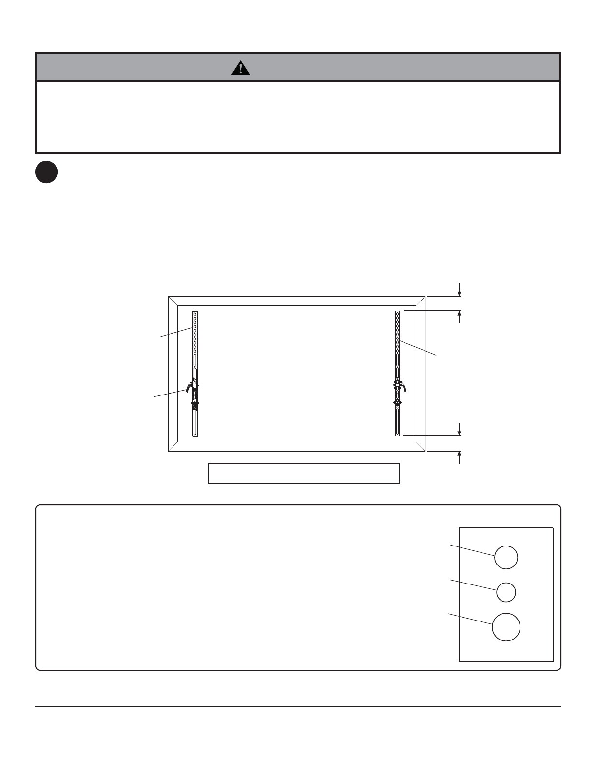
To prevent scratching the display, set a cloth on a fl at, level surface that will support the weight of the display. Place
2
display face side down. Refer to display manufacturers instructions or customer service, for removing any knobs,
base, cover or screw(s) on the back of the display to prepare mounting. These need to be removed to allow the tilt
brackets to be attached. Select the small, medium, large or extra large screws from the baffl ed fastener pack then
attach tilt brackets to display following fi gure 2.1 or 2.2.
NOTE: Top and bottom mounting holes on display must be used for attaching brackets.
NOTE: Be sure to attach tilt brackets with handles facing outward as shown below. Verify that all holes are properly
aligned, and then tighten screws using a phillips screwdriver or 4 mm allen wrench (FF).
X
BB
CENTER BRACKETS VERTICALLY
ON BACK OF DISPLAY
HANDLE FACE
OUT
Note: "X" dimensions should be equal.
Notes:
• The number of fasteners used will vary,
depending upon the type of display.
• Multi-washers and spacers may not be used,
depending upon the type of display.
• Use the corresponding hole in the multiwasher that matches your screw size as
shown.
• Slots in ST680 models are wider and require
the use of the M8 washer.
CC
X
MULTI-WASHER
MEDIUM HOLE FOR M5 SCREWS
SMALL HOLE FOR M4 SCREWS
LARGE HOLE FOR M6 SCREWS
NOTE: For fl at back displays proceed to step 2-1. For bump-out or recessed back display skip to step 2-2.
7 of 32
ISSUED: 09-30-11 SHEET #: 203-9051-1
Page 8
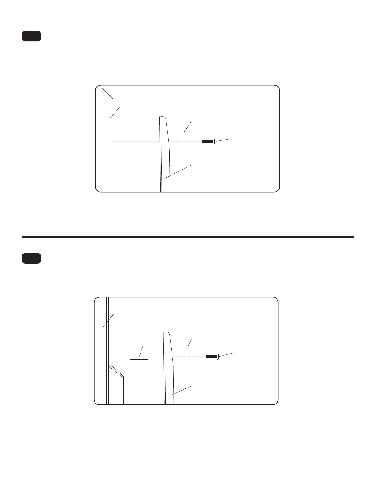
For Flat Back Display
2-1
Begin with the shortest length screw, hand thread through multi-washer and tilt bracket into display as shown
below. Screw must make at least three full turns into the mounting hole and fi t snug into place. Do not over
tighten. If screw cannot make three full turns into the display, select a longer length screw from the baffl ed
fastener pack. Repeat for remaining mounting holes, level brackets and tighten screws.
NOTE: Spacers may not be used, depending upon the type of display.
NOTE: If using M10 x 15mm penta-pin
If you have any questions, please call Peerless customer care at 1-800-865-2112.
DISPLAY
TM
screws, tighten screws with Penta-pinTM driver (I).
fi g. 2.1
MULTI-WASHER
SCREW
TILT BRACKET
(BB,CC)
For Bump-out or Recessed Back Display
2-2
Begin with longer length screw, hand thread through multi-washer, tilt bracket and spacer in that order into display
as shown below. Screw must make at least three full turns into the mounting hole and fi t snug into place. Do not
over tighten. If screw cannot make three full turns into the display, select a longer length screw from the baffl ed
fastener pack. Repeat for remaining mounting holes, level brackets and tighten screws.
NOTE: If using M10 x 15mm penta-pin
DISPLAY
SPACER
If you have any questions, please call Peerless customer care at 1-800-865-2112.
TM
screws, tighten screws with Penta-pinTM driver (I).
fi g. 2.2
MULTI-WASHER
SCREW
TILT BRACKET
(BB,CC)
8 of 32
ISSUED: 09-30-11 SHEET #: 203-9051-1
Page 9
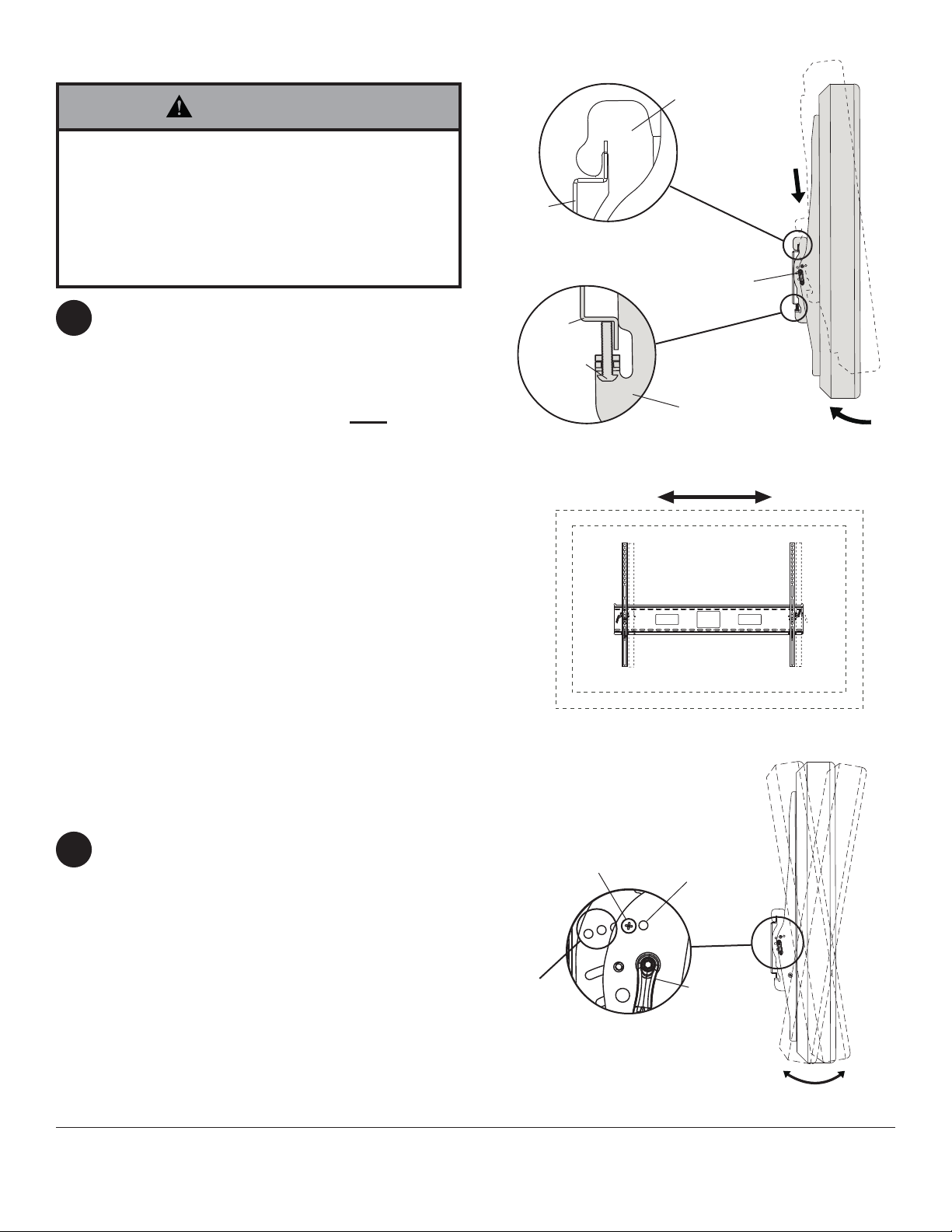
Mounting and Removing Flat Panel Display
WARNING
• Always use an assistant or mechanical lifting
equipment to safely lift and position the fl at panel
display.
• Do not tighten screws with excessive force.
Overtightening can cause damage to mount. Tighten
screws to 40 in. • lb (4.5 N.M.) maximum torque.
• Be careful not to pinch fi ngers when pushing display
from the bottom.
Tension Adjustment of Ratchet Handle: Adjust
3
tension in tilt brackets (BB & CC) by rotating ratchet
handle. NOTE: If obstruction prevents ratchet
handle from rotating, pull handle out while turning
will allow handle to reposition without tightening.
Release and turn handle to tighten or loosen.
Mounting Display: Ratchet handle must be in the
up or down position or interference will occur while
hooking tilt brackets to wall plate (AA). Slowly hook
tilt brackets (BB & CC) onto wall plate (AA) and
swing display down as shown in fi g. 3.1. Tilt bracket
hooks must fully engage wall plate as shown in
detail 2. Using phillips screw driver or security allen
wrench (FF), turn safety/security screws on tilt
brackets (BB & CC) clockwise till screw tip securely
contacts wall plate as shown in cross section.
Display Adjustment: Display can be adjusted
horizontally by loosening safety/security screws
on tilt brackets (BB & CC) three full turns. Adjust
display as shown in fi gure 3.2. Tighten safety/
security screws on tilt brackets till screw tip securely
contacts wall plate as shown in cross section.
Removing Display: To remove display from mount,
loosen safety screws, swing display away from
mount, and lift display off of mount.
AA
DETAIL 2
AA
SAFETY/
SECURITY
SCREW
CROSS SECTION
BB,CC
RATCHET
HANDLE
BB,CC
fi g. 3.1
fi g. 3.2
Adjusting the Tilt Angle of the Flat Panel Display
For preset tilt angles use Increlok™ and for custom
4
tilt angle use ratchet handle.
INCRELOK™: The display can be locked into a
pre-set tilt position of -5°, 0°, 5°, 10° or 15°. Use
locator hole to fi nd tilt position hole and tilt display
to align holes. Tighten IncreLok™ tilt locking screws
on both tilt brackets to lock tilt as shown in detail 3.
Ratchet Handle: Loosen ratchet handle (refer to
step 3 for tension adjustment of handle). Push or
pull from top or bottom of display to adjust tilt as
shown in fi gure 4.1. The tilt can be adjusted to a
maximum of 15° forward or 5° backward.
9 of 32
IncreLok™
TILT LOCKING
SCREW
TILT
POSITION
HOLES
LOCATOR
HOLE
RATCHET
HANDLE
DETAIL 3
fi g. 4.1
ISSUED: 09-30-11 SHEET #: 203-9051-1
Page 10

Recommended Cleaning Guidelines
The following procedures are not guaranteed to
control infection. An infection control administrator or
epidemiologist should be consulted regarding cleaning
procedures and processes.
Most painted components will withstand cleaning by
commonly used, diluted, non-abrasive solutions such
as quaternary ammonia compounds, ammonia enzyme
cleaners, and bleach or alcohol solutions. However,
it is recommended that any surface be tested in an
inconspicuous area prior to determine the propensity for
discoloration.
• Pen or permanent and dry erase markers can be
removed with 91% isopropyl alcohol and a soft cloth.
• Iodine stains can be removed with commonly used
cleaners and a soft cloth.
• Never use steel wool or other abrasive materials that will
damage the surface fi nish.
• Do not use Acetone, mineral spirits, abrasive cleansers,
paint thinner or any other harsh or toxic chemicals to clean
your product. These solvents will damage the surface
fi nish.
WARNING
• To avoid risk of electric shock, do not expose
electrical components to water, cleaning solutions or
other potentially corrosive liquids or substances.
• Do not use fl ammable cleaners on product surfaces
due to close proximity of electrical power and
equipment.
10 of 32
All other brand and product names are trademarks or registered trademarks of their respective owners.
ISSUED: 09-30-11 SHEET #: 203-9051-1
© 2011, Peerless Industries, Inc. All rights reserved.
Peerless Industries, Inc.
2300 White Oak Circle
www.peerlessmounts.com
Aurora, Il 60502
Page 11

Instalación y ensamblaje: Médico Antimicrobiano Soporte
p
universal de pared con capacidad de inclinación para pantallas
planas
o
de modelo
N.
ST670-AB, ST670-AW 42" - 71" (107 - 180 cm) 250 lb (113 kg)
ST680-AB, ST680-AW 61" - 102" (155 - 259 cm) 350 lb (159 kg)
Gama de tamaño de las
antallas
Capacidad de carga máxima
de UL
Características:
• Sostiene el televisor a sólo 3.04" (77mm) de la pared para proporcionar una instalación discreta
• El diseño de la placa de pared permite acceso a la pared y brinda múltiples opciones para el manejo de cables
• Los soportes inclinables universales se enganchan con facilidad a la placa de pared para proporcionar una instalación
rápida
• Inclinación ajustable hacia delante de hasta 15° y hacia atrás de hasta -5° para ver el televisor desde un ángulo óptimo
• El soporte inclinable universal preapretado permite ajustar el ángulo de inclinación con un solo movimiento sencillo
• La palanca de agarre fácil fi ja la posición de la pantalla con seguridad
• La función opcional IncreLok™ ofrece ángulos de inclinación predeterminados en incrementos de -5°, 0°, 5°, 10° y 15°
• Incluye el paquete de sujetadores Sorted-For-You™ para instalaciones en montantes de madera, concreto y bloques de
hormigón de escorias
• Ajuste horizontal opcional de hasta 8" (203mm) (dependiendo del modelo de la pantalla) para la colocación perfecta de
la pantalla
• Tratado con Agion
®
acabado médico antimicrobiano negro o blanco diseñado para ayudar en el control de infecciones.
2300 White Oak Circle • Aurora, Il 60502 • (800) 865-2112 • Fax: (800) 359-6500 • www.peerlessmounts.com
PUBLICADO: 09-30-11 HOJA #: 203-9051-1
Page 12

Español
NOTA: Lea la hoja de instrucciones completa antes de comenzar la instalación y el ensamblaje.
ADVERTENCIA
• No comience a instalar su producto de Peerless hasta haber leído y entendido las instrucciones y las advertencias
contenidas en la Hoja de Instalación. Si tiene alguna pregunta acerca de cualquiera de las instrucciones o las
advertencias, por favor, llame a Servicio al Cliente de Peerless al 1-800-865-2112 si está en EE. UU. Si es un cliente
internacional, por favor, comuníquese con su distribuidor local.
• Este producto sólo debe ser instalado por una persona que tenga una buena aptitud mecánica, que tenga
experiencia en construcción básica de edifi cios y que entienda estas instrucciones en su totalidad.
• Asegúrese de que la superfi cie de apoyo sostendrá, con seguridad, la carga combinada del equipo y todos los
fi jadores y componentes.
• Nunca sobrepase la capacidad máxima de soportar carga. Vea la página 11.
• Si va a instalar el producto en una pared con montantes de madera, asegúrese de que los tornillos de montaje estén
anclados en el centro de los montantes. Se recomienda utilizar un localizador de montantes de "borde a borde".
• Siempre cuente con la ayuda de un asistente o utilice un equipo mecánico de izar para levantar y colocar el equipo
con más seguridad.
• Apriete los tornillos con fi rmeza, pero no en exceso. Apretarlos en exceso puede dañar los artículos y puede
disminuir signifi cativamente su fuerza de fi jación.
• Este producto está diseñado para uso en interiores solamente. Utilizar este producto en exteriores podría causar
fallas del producto y lesiones a individuos.
• Este producto fue diseñado para ser instalado en paredes con la siguiente construcción solamente:
CONSTRUCCIÓN DE LA PARED ACCESORIOS NECESARIOS
• Montante de madera Incluido
• Viga de madera Incluido
• Concreto macizo Incluido
• Bloque de hormigón de escorias Incluido
• Montante de metal No lo instale excepto con el juego de accesorios de Peerless para
montantes de metal - ACC615; (no evaluados por UL)
• Ladrillo Comuníquese con un profesional califi cado (no evaluados por UL)
• ¿Otra superfi cie o no está seguro? Comuníquese con un profesional califi cado (no evaluados por UL)
Herramientas necesarias para el ensamblaje
• localizador de montantes (se recomienda uno de "borde a borde")
• destornillador phillips
• taladro
• broca de 5/16" (8mm) para paredes de concreto y de bloque de hormigón de escorias
• broca de 5/32" (4mm) para paredes con montantes de madera
• nivel
Contenido
Lista de piezas......................................................................................................................................................................13
Instalación en una pared con montantes de madera triples .................................................................................................15
Instalación en una pared de concreto macizo o de bloques de hormigón de escorias ........................................................16
Instalación de los soportes inclinables ................................................................................................................................. 17
Instalación y desinstalación de la pantalla plana .................................................................................................................19
Recomendaciones para la limpieza......................................................................................................................................20
12 de 32
PUBLICADO: 09-30-11 HOJA #: 203-9051-1
Page 13

Antes de comenzar, asegúrese de que su producto contiene todas las piezas que se muestran.
ST670-AB
ST670-AW
II
M10 x 2 Penta-pin (solo SF680)
1
520-9260
520-9260
Algunas partes pueden diferir un poco de las ilustradas.
Lista de piezas
Español
Descripción
AAplaca de pared 1 200-S1901 200-S2901
BB soporte inclinable izquierdo 1 201-S1474 201-S2474
CC soporte inclinable derecho 1 201-S1476 201-S2476
DD tornillo para madera de 14 x 2.5" 6 5S1-015-C03 5S1-015-C03
EE anclaje para concreto 6 590-0320 590-0320
FF llave allen de 4 mm 1 560-1727 560-1727
GG tornillo M10 x 15 mm (solo SF680) 4 520-9263 520-9263
HH arandela (solo SF680) 6 5W1-035-X01 5W1-035-X01
"
AA
-
™
BB
ST680-AB
200-S1902 200-S2902
201-S1478 201-S2478
201-S1480 201-S2480
-
DD
ST680-AW
-
CC
EE
FF
GG HH II
13 de 32
PUBLICADO: 09-30-11 HOJA #: 203-9051-1
Page 14

Español
Sujetadores aseguradores para los soportes inclinables
M4 x 12mm (6)
(510-1079)
M8 x 40mm (4)
(520-1152)
M4 x 25mm (4)
(510-1082)
M6 x 30mm (4)
(520-1067)
M5 x 12mm (4)
(520-1064)
M6 x 20mm (4)
(520-9554)
M5 x 25mm (4)
(520-1122)
M8 x 25mm (4)
(520-1101)
M6 x 12mm (4)
(520-1050)
.5" espaciador (4)
(540-1057)
.75" espaciador (4)
(540-1059)
M8 x 15mm (6)
(520-1068)
M6 x 25mm (4)
(520-1211)
arandela múltiple (6)
(580-1036)
14 de 32
PUBLICADO: 09-30-11 HOJA #: 203-9051-1
Page 15

Español
Instalación en una Pared con Montantes de Madera Triples
ADVERTENCIA
• El instalador debe verifi car que la superfi cie de apoyo sea capaz de soportar fi rmemente la carga combinada del
equipo y todos los herrajes y componentes.
• Apriete los tornillos para madera de tal modo que la placa de apoyo quede fi rmemente sujeta, pero no apriete en
exceso. El apriete excesivo puede dañar los tornillos, reduciendo enormemente su fuerza de fi jación.
• Nunca apriete más de 80 pulg-lb (9 N•m).
• Asegúrese de que los tornillos de montaje queden bien fi jos en el centro del montante. Se recomienda usar un
localizador de montantes de "borde a borde".
• Dos tornillos para madera (DD) debe estar instalado en la placa de pared (AA) en cada segmento, como se muestra
en detalle 1 o producto puede fallar.
• Los herrajes suministrados son para fi jar el soporte a través de tabique de yeso-cartón o yeso de espesor estándar
a los montantes de madera. Los instaladores son responsables de suministrar los herrajes para otros tipos de
situaciones de montaje (no evaluados por UL).
La placa de pared (AA) se puede instalar en tres montantes que tengan una separación de 16" (41 cm). Utilice
1
un localizador de montantes para localizar los bordes de los montantes. Se recomienda utilizar un localizador
de montantes de “borde a borde”. Tomando los bordes como punto de referencia, trace una línea vertical por el
centro de cada montante. Para los modelos de ST670 la parte superior ranuras de montaje debe ser 2,9" (74mm)
encima del centro de la pantalla deseada como se muestra en la fi gura 1.1. Para los modelos de ST680 la ranura
de montaje superior debe ser 1.3" por debajo del centro de la pantalla deseada. Nivele la placa y marque el centro
de los seis agujeros de montaje. Asegúrese de que los agujeros de montaje estén sobre las líneas que trazó por
el centro de los montantes. Taladre seis agujeros de 5/32" (4mm) de diámetro y 2.5" (64mm) de profundidad.
Asegúrese de que la placa esté nivelada, fíjela utilizando seis tornillos para madera de 14 x 2.5" (DD), como se
muestra en la fi gura 1.2.
Pase al paso 2.
NOTA: La placa de pared se puede instalar a una distancia de hasta 6" (152mm) del centro, como se muestra en
la fi gura 1.1.
MONTANTE
6"
(152 mm)
AA
CP = centro de la pantalla
DETALLE 1
CP
6"
(152 mm)
"X"
fi g. 1.1
AA
DD
SEGMENTO 1 SEGMENTO 2 SEGMENTO 3
15 de 32
fi g. 1.2
PUBLICADO: 09-30-11 HOJA #: 203-9051-1
Page 16

Instalación en una Pared de Concreto Macizo o de
Español
Bloques de Hormigón de Escorias
ADVERTENCIA
• Cuando instale soportes de pared Peerless en bloques de hormigón de escorias, verifi que que tengan un mínimo de 1-3/8" (35mm) de superfi cie
efectiva de concreto en el agujero que va a utilizar para los anclajes de concreto. ¡No perfore en las juntas de mortero! Asegúrese de instalar el
soporte en una parte sólida del bloque, generalmente a un mínimo de 1" (25mm) del costado del bloque. El bloque de hormigón de escorias debe
ser de conformidad con las especifi caciones C-90 de ASTM. Se sugiere taladrar el agujero con un taladro eléctrico normal en velocidad lenta en
vez de un taladro percutor para evitar romper la parte trasera del agujero al entrar en un espacio o cavidad.
• Dos tornillos para madera (DD) debe estar instalado en la placa de pared (AA) en cada segmento, como se muestra en detalle 1 o producto puede
fallar.
• El concreto debe tener una densidad mínima de 2000 psi. Un concreto menos denso podría no ser capaz de sujetar el anclaje para concreto.
• El instalador debe verifi car que la superfi cie de apoyo sea capaz de soportar fi rmemente la carga combinada del equipo y todos los herrajes y
componentes.
Asegúrese de que la placa de pared (AA) esté nivelada
1
y utilícela como plantilla para marcar cuatro agujeros de
montaje. Para los modelos de ST670 la parte superior
ranuras de montaje debe ser 2,9" (74mm) encima del
centro de la pantalla deseada como se muestra en la
fi gura 1.1 de la página 15. Para los modelos de ST680 la
ranura de montaje superior debe ser 1.3" por debajo del
centro de la pantalla deseada. Taladre cuatro agujeros
de 5/16" (8mm) de diámetro con una profundidad mínima
de 2.5" (64mm). Inserte los anclajes (EE) en los agujeros
a ras con la pared, como se muestra (a la derecha).
Coloque la placa de pared sobre los anclajes y fíjela con
los tornillos de 14 x 2.5" (DD). Nivele y apriete todos los
sujetadores.
ADVERTENCIA
• Apriete los tornillos de tal modo que la placa de apoyo quede
fi rmemente sujeta, pero no los apriete en exceso. El apriete
excesivo puede dañar los tornillos, reduciendo enormemente su
fuerza de fi jación.
• Nunca apriete más de 80 pulg-lb (9 N•m).
• Siempre fi je los anclajes de expansión directamente al concreto
que soporta carga.
• Nunca fi je los anclajes de expansión a una pared de concreto
recubierta con yeso, tabiques de yeso-cartón u otro material de
acabado. Si el montaje a superfi cies de concreto recubiertas
con una superfi cie de acabado es inevitable (no evaluados por
UL), será necesario escariar el acabado, como se muestra más
abajo. Asegúrese de que los anclajes de concreto no se alejen del
concreto al apretar los tornillos. Si el grosor de la pared de yeso/
tabique de yeso-cartón es mayor que 5/8" (16mm), el instalador
deberá suministrar fi jaciones especiales (no evaluados por UL).
INCORRECTO CORRECTO
placa
de
pared
concreto
placa
pared
de
concreto
1
Perfore los agujeros y después inserte los anclajes (EE).
2
AA
DD
Coloque la placa (AA) sobre los anclajes (EE) y fíjela con
los tornillos (DD).
3
Apriete todas las fi jaciones.
CONCRETO MACIZO
EE
BLOQUE DE
HORMIGÓN
DE ESCORIAS
superfi cie de
concreto
EE
EE
VISTA EN CORTE
yeso / tabique de yeso-cartón
DETALLE 1
SEGMENTO 1 SEGMENTO 2 SEGMENTO 3
16 de 32
AA
DD
PUBLICADO: 09-30-11 HOJA #: 203-9051-1
Page 17

Español
Instalación de los soportes inclinables
ADVERTENCIA
• Apriete los tornillos de tal modo que los soportes adaptadores queden fi rmemente sujetos. No apriete aplicando demasiada
fuerza. El apriete excesivo puede causar daño por esfuerzo a los tornillos, reduciendo enormemente su fuerza de fi jación y
causando el posible desprendimiento de sus cabezas. Apriete los tornillos a 40 pulg-lb (4.5 N•m) de par torsor máximo.
• Si los tornillos no pueden atornillarse con tres vueltas completas en los insertos de la pantalla, o si los tornillos topan fondo y la
placa todavía no está fi rmemente sujeta, se podría dañar la pantalla o causar la falla del producto.
Para evitar rayar la pantalla, coloque un trapo sobre una superfi cie plana y nivelada que soporte el peso de la
2
pantalla.Coloque la pantalla boca abajo.Si la pantalla tiene perillas en la parte trasera, quítelas para poder fi jar los
soportes adaptadores. Fije los soportes adaptadores en la parte trasera de la pantalla utilizando la combinación
adecuada de tornillos, arandelas y espaciadores, como se muestra en la fi gura 2.1 o en la fi gura 2.2.
NOTA: Siempre se tienen que usar los agujeros superiores y los inferiores.
NOTA: Asegúrese de que fi ja los soportes con los mangos hacia fuera, como se muestra abajo. Verifi que que
todos los agujeros estén debidamente alineados y luego apriete los tornillos usando un destornillador phillips o
llave allen de 4 mm (FF).
X
BB
MANGOS HACIA
AFUERA
Notas:
• La cantidad de fi jaciones utilizada variará según el
tipo de pantalla.
• Es posible que no tenga que usar las arandelas
múltiples y los espaciadores, dependiendo del tipo
de pantalla.
• Use el agujero correspondiente en la arandela
múltiple que coincida con el tamaño de su tornillo,
como se muestra.
• Las ranuras de los modelos ST680 son más
anchas y requieren el uso de la arandela M8.
CENTRE LOS SOPORTES VERTICALMENTE EN LA
PARTE TRASERA DE LA PANTALLA
Nota: Las dimensiones "X" deben ser iguales.
CC
X
ARANDELA MÚLTIPLE
AGUJERO MEDIANO PARA TORNILLOS M5
AGUJERO PEQUEÑO PARA TORNILLOS M4
AGUJERO GRANDE PARA TORNILLOS M6
NOTA: En el caso de los televisores que tienen la parte posterior plana, pase al paso 2-1. En el caso de los
televisores que tienen la parte posterior abultada o empotrada, pase al paso 2-2.
17 de 32
PUBLICADO: 09-30-11 HOJA #: 203-9051-1
Page 18

Instalación de un televisor que tiene la parte posterior plana
2-1
Comience con uno de los tornillos más cortos, enrósquelo, con la mano, a través de la arandela múltiple y el
soporte adaptador a la parte posterior de la pantalla, como se muestra abajo. El tornillo debe dar, por lo menos,
tres vueltas completas dentro del agujero de instalación y debe quedar ajustado en su lugar. No apriete los
tornillos en exceso. Si el tornillo no puede dar tres vueltas completas al entrar en la parte posterior de la pantalla,
seleccione un tornillo más largo de los sujetadores identifi cados y clasifi cados en las divisiones del empaque
plástico. Siga el mismo procedimiento con los agujeros de instalación restantes, nivele los soportes y apriete los
tornillos.
NOTA: Es posible que no necesite usar los espaciadores, dependiendo del tipo de pantalla.
NOTA: Si usa los tornillos penta-pin
TM
de M10 x 15mm, apriételos con un desarmador penta-pinTM(I).
PANTALLA
ARANDELA
MÚLTIPLE
SOPORTE
INCLINABLE
(BB,CC)
Español
fi g. 2.1
TORNILLO
Si tiene alguna pregunta, por favor, llame a Servicio al Cliente de Peerless al 1-800-865-2112.
Instalación de un televisor que tiene la parte posterior abultada o empotrada
2-2
Comience con uno de los tornillos más largos, enrósquelo, con la mano, a través de la arandela múltiple, el
soporte adaptador y el espaciador, en ese orden, a la parte posterior de la pantalla, como se muestra abajo. El
tornillo debe dar, por lo menos, tres vueltas completas dentro del agujero de instalación y debe quedar ajustado
en su lugar. No apriete los tornillos en exceso. Si el tornillo no puede dar tres vueltas completas al entrar en la
parte posterior de la pantalla, seleccione un tornillo más largo de los sujetadores identifi cados y clasifi cados
en las divisiones del empaque plástico. Siga el mismo procedimiento con los agujeros de instalación restantes,
nivele los soportes y apriete los tornillos.
NOTA: Si usa los tornillos penta-pin
TM
de M10 x 15mm, apriételos con un desarmador penta-pinTM(I).
PANTALLA
ARANDELA
MÚLTIPLE
ESPACIADOR
SOPORTE
INCLINABLE
(BB,CC)
fi g. 2.2
TORNILLO
Si tiene alguna pregunta, por favor, llame a Servicio al Cliente de Peerless al 1-800-865-2112.
18 de 32
PUBLICADO: 09-30-11 HOJA #: 203-9051-1
Page 19

Instalación y desinstalación de la pantalla plana
Español
ADVERTENCIA
• Siempre cuente con un asistente o con un equipo
mecánico de izar para levantar y colocar los
televisores de pantalla plana con más seguridad.
• No apriete los tornillos con fuerza excesiva. Apretarlos
en exceso puede dañar el soporte. Apriete los tornillos
a un máximo de 40 pulg-lb (4.5 N•m) de par torsor.
• Tenga cuidado de no pincharse los dedos cuando
empuje palanca de la pantalla por la parte inferior.
Ajuste tensor de la palanca de trinquete: Ajuste la tensión
3
de los soportes inclinables (BB y CC) rotando la palanca de
trinquete. NOTA: Si una obstrucción le impide rotar la palanca
de trinquete, puede tirar de la palanca hacia fuera a la vez que
le da vuelta para poder colocarla en otra posición sin apretar los
soportes. Al dejar de tirar la palanca hacia fuera, la misma se
volverá a pegar del televisor en la posición que permite apretar o
afl ojar los soportes.
Instalar la pantalla: La palanca de trinquete tiene que estar
en la posición hacia arriba o hacia abajo o estorbará cuando
enganche los soportes inclinables a la placa de pared (AA).
Enganche los soportes inclinables (BB y CC) lentamente a la
placa de pared (AA) y gire la pantalla hacia abajo, como se
muestra en la fi gura 3.1. Los ganchos de los soportes inclinables
tienen que entrar completamente en la placa de pared, como
se muestra en el detalle 2. Usando un destornillador phillips o
una llave allen de seguridad (FF), déles vuelta los tornillos de
seguridad de los soportes inclinables (BB y CC) en el sentido
de las manecillas del reloj hasta que la punta del tornillo toque
fi rmemente la placa de pared, como se muestra en la sección
transversal.
Ajuste de la pantalla: La pantalla se puede ajustar
horizontalmente afl ojando los tornillos de seguridad de los
soportes inclinables (BB y CC) tres vueltas completas. Ajuste la
pantalla, como se muestra en la fi gura 3.2. Apriete los tornillos de
seguridad de los soportes inclinables hasta que la punta de los
tornillos toque fi rmemente la placa de pared, como se muestra
en la sección transversal.
Quitar la pantalla: Para quitar la pantalla del soporte, afl oje los
tornillos de seguridad, gire la pantalla retirándola del soporte y
levántela para sacarla del soporte.
AA
DETALLE 2
AA
TORNILLO DE
SEGURIDAD
SECCIÓN
TRANSVERSAL
BB,CC
PALANCA DE
TRINQUETE
BB,CC
fi g. 3.1
fi g. 3.2
Ajustar el ángulo de inclinación de
la pantalla
Para colocar la pantalla en ángulos de inclinación
predeterminados, utilice la función de IncreLok™; para ajustar la
4
inclinación como guste, utilice la palanca de trinquete.
INCRELOK™: La pantalla se puede ajustar a ángulos de
inclinación predeterminados de -5°, 0°, 5°, 10° ó 15°. Use el
agujero localizador para encontrar el agujero de inclinación e
incline la pantalla para alinear los agujeros. Apriete los tornillos
de fi jación de la inclinación IncreLok™ de ambos soportes
inclinables para fi jar la inclinación, como se muestra en el detalle
3.
Palanca de trinquete: Afl oje la palanca de trinquete (vea el
paso 3 para aprender sobre el ajuste tensor de la palanca).
Mueva la parte superior o la parte inferior de la pantalla tirando
de la misma o empujándola para ajustar la inclinación, como se
muestra en la fi gura 4.1. La inclinación se puede ajustar hasta un
máximo de 15° hacia delante o de 5° hacia atrás.
AGUJEROS DE
POSICIÓN DE
INCLINACIÓN
19 de 32
TORNILLO DE FIJACIÓN
DE LA INCLINACIÓN
INCRELOK™
DETALLE 3
AGUJERO
LOCALIZADOR
PALANCA DE
TRINQUETE
fi g. 4.1
PUBLICADO: 09-30-11 HOJA #: 203-9051-1
Page 20

Recomendaciones para la limpieza
No se garantiza que los siguientes procedimientos
controlarán las infecciones. Se debe consultar a un
manejador de control de infecciones o un epidemiólogo
respecto a los procedimientos y procesos de limpieza.
La mayoría de los componentes pintados resistirán la
limpieza con soluciones sin abrasivos diluidas de uso
común como los compuestos de amoniaco cuaternario,
limpiadores con enzimas de amoniaco y soluciones con
blanqueador o alcohol. Sin embargo, se recomienda que
se haga una prueba en un área discreta de la superfi cie
antes de determinar la propensión a descolorarse.
• Las marcas de bolígrafo o marcadores permanentes
y de borrado en seco se pueden eliminar con alcohol
isopropílico al 91% y un paño suave.
• Las manchas de yodo se pueden eliminar con
limpiadores de uso común y un paño suave.
• No use esponjas de acero ni otros materiales abrasivos
que puedan dañar el acabado de la superfi cie.
• No use acetona, alcoholes minerales, limpiadores
abrasivos, solvente de pintura ni ningún otro químico
áspero o tóxico para limpiar el producto. Estos solventes
dañarán el acabado de la superfi cie.
Español
ADVERTENCIA
• Para evitar el riesgo de choque eléctrico, no
exponga los componentes eléctricos al agua,
a soluciones limpiadoras ni a otros líquidos o
sustancias potencialmente corrosivos.
• No use limpiadores infl amables en las superfi cies
del producto debido a la proximidad a tomas de
corriente y otros equipos eléctricos.
20 de 32
Cualesquiera otras marcas y nombres de productos son marcas comerciales o registradas de sus respectivos dueños.
PUBLICADO: 09-30-11 HOJA #: 203-9051-1
© 2011, Peerless Industries, Inc. Todos los derechos reservados.
Peerless Industries, Inc.
2300 White Oak Circle
Aurora, Il 60502
www.peerlessmounts.com
Page 21

Installation et assemblage : Médicaux Antimicrobien
Support mural inclinable universel pour écrans plats
N° de modèle Plage de dimension de l’écran
ST670-AB, ST670-AW 42 - 71 po (107 - 180 cm) 250 lb (113 kg)
ST680-AB, ST680-AW
61 - 102 po (155 - 259 cm)
Capacité de charge UL
maximale
350 lb (159 kg)
Caractéristiques:
• Écran maintenu à 3.04 po (77mm) seulement du mur pour une installation discrète
• La conception de la plaque murale offre un accès mural permettant de nombreuses options de gestion du câblage
• Les supports inclinables universels s’accrochent facilement à la plaque murale pour une installation rapide
• Réglable jusqu'à 15° pour l'inclinaisonvers l’avant et jusqu'à -5° pour l'inclinaison vers l’arrière pour un angle de vue
optimal
• Le support inclinable universel prétendu permet de régler l’angle d’inclinaison en un seul mouvement facile.
• La poignée à prise facile verrouille l’écran en position
• La fonction IncreLok™ en option permet l’inclinaison par incréments de -5, 0, 5, 10 et 15°.
• Inclut un jeu de fi xations Sorted-For-You™ pour l’installation sur des montants en bois, du béton ou du bloc de béton
• Réglage horizontal en option jusqu'à 203mm (8 po) (en fonction du modèle d'écran) pour un positionnement parfait de
l'écran
• Traité avec Agion
®
fi ni médicaux antimicrobien noir ou blanc conçu pour aider à prévenir les infections.
2300 White Oak Circle • Aurora, Il 60502 • (800) 865-2112 • Fax: (800) 359-6500 • www.peerlessmounts.com
PUBLIÉ LE: 09-30-11 FEUILLE no: 203-9051-1
Page 22

Français
REMARQUE: lisez entièrement la fi che d’instructions avant de commencer l’installation et l’assemblage.
AVERTISSEMENT
• Ne commencez pas à installer votre produit Peerless avant d’avoir lu et assimilé les instructions et les avertissements
contenus dans cette fi che d’installation. Pour toute question concernant les instructions ou les avertissements,
veuillez appeler le service à la clientèle de Peerless au 1-800-865-2112; tous les clients internationaux sont priés de
contacter leur distributeur local.
• Ce produit doit être installé uniquement par quelqu’un possédant une bonne aptitude à la mécanique, une expérience
de la construction immobilière et ayant bien compris ces instructions.
• Assurez-vous que la surface de support puisse soutenir sans danger la charge totale de l’équipement ainsi que des
pièces et composants qui y sont attachés.
• Ne dépassez jamais la capacité de charge maximum. Reportez-vous à la page 21.
• Lors d’une installation sur un mur à montants en bois, assurez-vous que les vis de montage sont ancrées au centre
des montants. L’utilisation d’un localisateur de montants « bord à bord » est fortement recommandée.
• Pour lever et positionner l’équipement en toute sécurité, faites-vous toujours aider par une autre personne ou utilisez
un dispositif de levage mécanique.
• Serrez fermement les vis, mais sans excès. Un serrage excessif peut endommager les composants et en réduire
considérablement la capacité de support.
• Ce produit est conçu uniquement pour un usage intérieur. L’utilisation de ce produit à l’extérieur peut causer une
défaillance du produit et des blessures corporelles.
• Ce produit a été conçu uniquement pour une installation sur les types de murs ci-dessous :
TYPE DE MUR PIÈCES DE FIXATION REQUISES
• Montant en bois Incluses
• Poutre en bois Incluses
• Béton plein Incluses
• Bloc de béton de mâchefer Incluses
• Montant métallique Ne pas installer sur ce type de mur sauf à l’aide de l’ensemble d’accessoires
Peerless pour montants métalliques - ACC615; (non évalué UL)
• Brique Contacter un professionnel qualifi é (non évalué UL)
• Autre, ou vous n’êtes pas sûr ? Contacter un professionnel qualifi é (non évalué UL)
Outils nécessaires au montage
• localisateur de montants (un localisateur de montants « bord à bord » est recommandé)
• tournevis phillips
• perceuse
• foret de 5/16 po (8mm) pour les murs à block de béton
• foret de 5/32 po (4mm) pour les murs à montants en bois
• niveau
Table des matières
Liste des pièces ....................................................................................................................................................................23
Installation sur un mur à triples montants en bois ................................................................................................................ 25
Installation sur du béton plein ou un bloc de béton de mâchefer ......................................................................................... 26
Installation de support inclinables.........................................................................................................................................27
Installation de l’écran plat sur la plaque murale ...................................................................................................................29
Méthodes de nettoyage recommandées .............................................................................................................................. 30
22 sur 32
PUBLIÉ LE: 09-30-11 FEUILLE no: 203-9051-1
Page 23

Avant de commencer, veillez à ce que toutes les pièces énumérées soient incluses.
ST670-AB
ST670-AW
Les pièces peuvent différer légèrement de l’illustration.
Liste des pièces
Français
Description Qté
AAplaque murale 1 200-S1901 200-S2901
BB support inclinable gauche 1 201-S1474 201-S2474
CC support inclinable droit 1 201-S1476 201-S2476
DD vis à bois no 14 x 2,5 po 6 5S1-015-C03 5S1-015-C03
EE chevilles d'ancrage pur béton 6 590-0320 590-0320
FF clé hexagonale de 4 mm 1 560-1727 560-1727
GG vis M10 x 15 mm (seulement SF680) 4 520-9263 520-9263
HH rondelle (seulement SF680) 6 5W1-035-X01 5W1-035-X01
II M10 x 2 po Penta-pin™ (seulement SF680) 1 520-9260 520-9260
AA
BB
ST680-AB
200-S1902 200-S2902
201-S1478 201-S2478
201-S1480 201-S2480
DD
ST680-AW
CC
EE
FF
GG HH II
23 sur 32
PUBLIÉ LE: 09-30-11 FEUILLE no: 203-9051-1
Page 24

Fixations du supports inclinables avec sécurité
Français
M4 x 12mm (6)
(510-1079)
M8 x 40mm (4)
(520-1152)
M4 x 25mm (4)
(510-1082)
M6 x 30mm (4)
(520-1067)
M5 x 12mm (4)
(520-1064)
M6 x 20mm (4)
(520-9554)
M5 x 25mm (4)
(520-1122)
M8 x 25mm (4)
(520-1101)
M6 x 12mm (4)
(520-1050)
,5 po entretoise (4)
(540-1057)
,75 po entretoise (4)
M8 x 15mm (6)
(520-1068)
M6 x 25mm (4)
(520-1211)
rondelle
universelle (6)
(580-1036)
(540-1059)
24 sur 32
PUBLIÉ LE: 09-30-11 FEUILLE no: 203-9051-1
Page 25

Installation sur un Mur à Triples Montants en Bois
Français
AVERTISSEMENT
• L’installateur doit s’assurer que la surface de support pourra soutenir sans danger la charge combinée de
l’équipement, de toute sa visserie et de tous ses composants.
• Serrez les vis à bois de manière que la plaque murale soit fermement fi xée, mais sans excès. Un serrage excessif
peut endommager les vis et en réduire considérablement le pouvoir de maintien.
• Ne serrez jamais à plus de 9 Nm (80 po-lb).
• Assurez-vous que les vis de montage sont ancrées au centre des montants. L’usage d’un localisateur de montants
« bord à bord » est fortement conseillé.
• Deux vis à bois (DD) doit être installé dans le mur la plaque (AA) dans chaque segment comme le montre en détail
une ou d'un produit peut échouer.
• La visserie est fournie pour fi xer la monture à travers une cloison sèche ou du plâtre d’épaisseur standard et dans
des montants en bois. Il appartient aux installateurs de fournir la visserie nécessaire pour d’autres types de situations
(non évalué UL).
La plaque murale (AA) peut être installée sur trois montants espacés de 41cm (16 po). Repérez le bord des
1
montants à l’aide d’un localisateur de montants. L’utilisation d’un localisateur de montants « bord à bord » est
fortement recommandée. Après avoir repéré les bords, tracez une ligne verticale le long du centre de chaque
montant. Posez la plaque murale sur le mur et utilisez-la comme gabarit. Pour les modèles ST670 haut slots de
montage doit être 2,9 po (74mm) au-dessus du Centre de l'écran de votre choix comme illustré à la fi gure 1.1.
Pour les modèles ST680 l'emplacement de montage supérieure doit être 1,3 po sous le centre de l'écran de votre
choix. Mettez la plaque à niveau et marquez le centre des six trous de fi xation. Veillez à ce que les trous de fi
xation soient sur la ligne médiane du montant. Percez six trous de 4mm (5/32 po) de dia. et de 64mm (2,5 po) de
profondeur. Veillez à ce que la plaque murale soit de niveau et fi xez-la à l’aide de six vis à bois n° 14 x 2,5 po (DD)
comme illustré à la fi gure 1.2.
Passez à l’étape 2.
REMARQUE: La plaque murale peut être décentrée de jusqu’à 152mm (6 po) comme illustré à la fi gure 1.1.
MONTANT
6 po
(152 mm)
AA
CE = centre de l’écran
CE
DÉTAIL 1
6 po
(152 mm)
"X"
fi g. 1.1
AA
DD
SEGMENT 1 SEGMENT 2 SEGMENT 3
25 sur 32
fi g. 1.2
PUBLIÉ LE: 09-30-11 FEUILLE no: 203-9051-1
Page 26

Installation sur du Béton Plein ou un Bloc de Béton de Mâchefer
Français
AVERTISSEMENT
• Si vous installez des montures murales Peerless sur un bloc de béton de mâchefer, vérifi ez que vous disposez d’une épaisseur de béton d’au
moins 35mm (1 3/8 po) dans le trou destiné aux ancrages de béton. Ne percez pas dans les joints de mortier ! Veillez à effectuer le montage
dans une partie pleine du bloc, généralement à au moins 25mm (1 po) du côté du bloc. Le bloc de béton de mâchefer doit être conforme aux
spécifi cations de l’ASTM C-90. Pour percer le trou, il est conseillé d’utiliser une perceuse électrique standard sur un réglage bas au lieu d’un
marteau perforateur, afi n d’éviter de briser la partie arrière du trou lorsque vous pénétrez un vide ou une cavité.
• Deux vis à bois (DD) doit être installé dans le mur la plaque (AA) dans chaque segment comme le montre en détail une ou d'un produit peut
échouer.
• Le béton doit avoir une densité minimum de 2 000 psi. Un béton de densité moindre risquerait de ne pas retenir un ancrage de béton.
• Assurez-vous que la surface de support pourra soutenir sans danger la charge combinée de l’équipement, de toute sa visserie et de tous ses
composants.
Assurez-vous que la plaque murale (AA) est de
1
niveau et utilisez-la comme gabarit pour marquer
l’emplacement des quatre trous de fi xation. Pour
les modèles ST670 haut slots de montage doit être
2,9 po (74mm) au-dessus du Centre de l'écran de
votre choix comme illustré à la fi gure 1.1 en el page
25. Pour les modèles ST680 l'emplacement de
montage supérieure doit être 1,3 po sous le centre
de l'écran de votre choix. Percez quatre trous de
8mm (5/16 po) de dia. à une profondeur minimale
de 64mm (2,5 po). Insérez les chevilles d’ancrage
(EE) dans les trous au ras du mur comme illustré
(à droite). Posez la plaque murale sur les chevilles
d’ancrage et attachez-la à l’aide de vis n° 14 x 2,5
po (DD). Assurez-vous qu’elle est de niveau, puis
serrez toutes les fi xations.
AVERTISSEMENT
• Serrez les vis de manière que la plaque murale soit fermement fi xée,
mais sans excès. Un serrage excessif peut endommager les vis et
en réduire considérablement le pouvoir de maintien.
• Ne serrez jamais à plus de 9 Nm (80 po-lb).
• Fixez toujours des ancrages de béton directement sur du béton
porteur.
• Ne fi xez jamais d’ancrages sur du béton recouvert de plâtre, une
cloison sèche ou autre matériau de fi nition. Si vous ne pouvez pas
éviter d’effectuer le montage sur du béton recouvert d’une surface
de fi nition, celle-ci doit être chambrée (non évalué UL), comme
indiqué cidessous. Assurez-vous que les ancrages de béton ne se
séparent pas du béton lorsque vous serrez les vis. Si l’épaisseur du
plâtre / de la cloison sèche dépasse 16mm (5/8 po), des fi xations
adaptées devront être fournies par l’installateur (non évalué UL).
1
Percez des trous et insérez les ancrages (EE).
2
AA
DD
Placez la plaque (AA) sur les ancrages (EE) et fi xez avec
des vis (DD).
3
Serrez toutes les fi xations.
BÉTON PLEIN
EE
BLOC DE BÉTON
DE MÂCHEFER
surface en
béton
EE
EE
INCORRECT
plaque
mural
plâtre /
VUE EN COUPE
cloison sèche
béton
plaque
mural
plâtre /
cloison sèche
DÉTAIL 1
SEGMENT 1 SEGMENT 2 SEGMENT 3
CORRECT
béton
26 sur 32
AA
DD
PUBLIÉ LE: 09-30-11 FEUILLE no: 203-9051-1
Page 27

Français
Installation des support inclinables
AVERTISSEMENT
• Serrez les vis de manière à ce que les support adaptateurs tiennent solidement en place. N’exercez pas une force
excessive pour serrer. Un serrage excessif peut endommager les vis, réduire considérablement leur capacité de
support et, éventuellement, faire tomber les têtes de vis. Serrez à un couple maximal de 40 po-lb (4,5 Nm).
• Si les vis ne sont pas enfoncées de trois tours complets dans les inserts ou si elles sont serrées au maximum sans
parvenir à fi xer solidement le support, l’écran peut être abîmé ou le produit détérioré.
Afi n d’éviter de rayer l’écran, posez un morceau de tissu sur une surface plane et de niveau qui peut supporter le
2
poids de l’écran. Déposez l’écran à plat, tourné vers le bas. Si l’écran possède des boutons à l’arrière, enlevez-les
pour pouvoir attacher les supports adaptateurs. Fixez les supports adaptateurs à l’arrière de l’écran à l’aide des vis,
rondelles universelles et entretoises appropriées, comme illustré sur la fi gure 2.1 ou 2.2.
REMARQUE: Les trous supérieurs et inférieurs doivent toujours être utilisés.
REMARQUE: Assurez-vous de fi xer les supports inclinables de façon à ce que les poignées soient tournées vers
l’extérieur comme illustré ci-dessous. Veillez à ce que tous les trous soient bien alignés, puis serrez les vis à l’aide
d’un tournevis cruciforme ou clé hexagonele de 4 mm (FF).
X
BB
POIGNÉES TOURNÉES
VERS L’EXTÉRIEUR
RONDELLE
UNIVERSELLE
CENTREZ LES SUPPORTS
VERTICALEMENT À
L’ARRIÈRE DE L’ÉCRAN
REMARQUE: Les dimensions " X " doivent être égales.
REMARQUES:
• Le nombre de fi xations utilisées varie suivant le type
TROU MOYEN POUR VIS M5
PETIT TROU POUR VIS M4
GROS TROU POUR VIS M6
d’écran.
• Il est possible que les rondelles universelles et les
entretoises ne soient pas utilisées, suivant le type
d’écran.
• Utilisez le trou correspondant dans la rondelle
universelle adaptée à la taille de l’écran, comme illustré.
• Sur les modèles ST680 les fentes sont plus larges et
nécessitent l’usage de rondelles M8
CC
X
REMARQUE : Pour les écrans à dos plat, exécutez l’étape 2-1. Pour les écrans à dos convexes ou concaves
passez à l’étape 2-2.
27 sur 32
PUBLIÉ LE: 09-30-11 FEUILLE no: 203-9051-1
Page 28

Pour les écrans à dos plat
2-1
Commencez par la vis la plus courte et vissez-la manuellement à l’écran en la faisant passer à travers la rondelle
universelle et le support inclinable, comme indiqué ci-dessous. La vis doit effectuer au moins trois tours complets
dans le trou de fi xation et tenir solidement en place. Ne pas trop serrer. S’il est impossible d’effectuer trois tours
de vis complets, choisissez une vis plus longue dans le jeu de fi xations à compartiments. Répétez pour le reste
des trous de fi xations, mettez les supports à niveau et resserrez les vis.
REMARQUE: Il n’est pas toujours nécessaire d’utiliser des entretoises, selon le type d’écran.
REMARQUE: Si des vis penta-pin
serrer.
ÉCRAN
TM
M10 x 15mm sont utilisées, utilisez le tournevis Penta-pinTM (I) pour les
fi g. 2.1
RONDELLE
UNIVERSELLE
VIS
SUPPORT
INCLINABLE
(BB,CC)
Français
Pour toute question, veuillez appeler le service à la clientèle de Peerless au 1-800-865-2112
Pour un écran à dos convexe ou concave
2-2
Commencez par la vis la plus longue et vissez-la manuellement à l’écran en la faisant passer à travers la
rondelle universelle, le support inclinable et l’entretoise comme indiqué ci-dessous. La vis doit effectuer au moins
trois tours complets dans le trou de fi xation et tenir solidement en place. Ne pas trop serrer. S’il est impossible
d’effectuer trois tours de vis complets, choisissez une vis plus longue dans le jeu de fi xations à compartiments.
Répétez pour le reste des trous de fi xations, mettez les supports à niveau et resserrez les vis.
REMARQUE : Si des vis penta-pin
serrer.
ÉCRAN
TM
M10 x 15mm sont utilisées, utilisez le tournevis Penta-pinTM (I) pour les
ENTRETOISE
fi g. 2.2
RONDELLE
UNIVERSELLE
VIS
SUPPORT
INCLINABLE
(BB,CC)
Pour toute question, veuillez appeler le service à la clientèle de Peerless au 1-800-865-2112
28 sur 32
PUBLIÉ LE: 09-30-11 FEUILLE no: 203-9051-1
Page 29

Installation de l’écran plat sur la plaque murale
Français
AVERTISSEMENT
• Pour lever et positionner l’écran plat en toute sécurité,
faites-vous toujours aider par une autre personne ou
utilisez un dispositif de levage mécanique.
• N’exercez pas une force excessive sur les vis. Un
serrage excessif peut endommager le support. Serrez
les vis à un couple maximal de 40 po-lb (4,5 Nm).
• Veillez à ne pas vous pincer les doigts lorsque vous
poussez l’écran par le bas.
Réglage de la tension de la poignée à cliquet: Réglez
3
la tension des supports inclinables (BB et CC) en tournant
la poignée à cliquet. REMARQUE: Si une obstruction
empêche la poignée à cliquet de tourner, retirez la
poignée tout en tournant pour la repositionner sans serrer.
Relâchez et tournez la poignée pour serrer ou desserrer.
Montage de l’écran: La poignée à cliquet doit être
en position relevée ou abaissée pour ne pas créer
d’interférence lors de la fi xation des supports inclinables à
la plaque murale (AA). Accrochez lentement les supports
inclinables (BB et CC) sur la plaque murale (AA) et
faites basculer l’écran vers le bas comme illustré à la
fi g. 3.1. Les crochets des supports inclinables doivent
s’enclencher complètement dans la plaque murale comme
illustré dans le détail 2. À l’aide d’un tournevis cruciforme
ou d'une clé hexagonale (FF), tournez le vis de sûreté/
sécurité sur les supports inclinables (BB et CC) dans le
sens horaire jusqu'à ce que l'extrémité de la vis entre bien
en contact avec la plaque murale comme illustré dans la
vue en coupe.
Réglage de l’écran: L’écran peut être réglé
horizontalement en desserrant les vis de sûreté/
sécurité sur les supports inclinables (BB et CC) de trois
tours complets. Réglez l’écran comme illustré à la fi g.
3.2. Serrez les vis de sûreté/sécurité sur les supports
inclinables jusqu’à ce que les extrémités des vis entrent
bien en contact avec la plaque murale comme illustré
dans la vue en coupe.
Retrait de l’écran: Pour retirer l’écran du support,
desserrez les vis de sûreté, faites pivoter l’écran à l’écart
du support et soulevez-le.
Réglage de l’inclinaison de l’écran plat
Pour les angles d’inclinaison préréglés, utilisez la fonction
4
Increlok™ et pour les angles d’inclinaison sur mesure,
utilisez la poignée à cliquet.
INCRELOK™: L’écran peut être verrouillé dans une
position d’inclinaison préréglée de -5, 0, 5, 10 ou 15°.
Utilisez le trou de positionnement pour trouver le trou
d’inclinaison et inclinez l’écran pour aligner les trous.
Serrez les vis de verrouillage de l’inclinaison IncreLok™
sur les deux supports inclinables pour verrouiller la
position comme illustré dans le détail 3.
Poignée à cliquet: Desserrez la poignée à cliquet (voir
l’étape 3 pour le réglage de la tension de la poignée).
Poussez ou tirez depuis le haut ou le bas de l’écran
pour régler l’inclinaison comme illustré à la fi gure 4.1.
L’inclinaison peut être réglée à un maximum de 15° vers
l’avant ou 5° vers l’arrière.
29 sur 32
AA
DÉTAIL 2
AA
VIS DE
SÛRETÉ/
SÉCURITÉ
COUPE
TRANSVERSALE
VIS DE BLOCAGE
DE L’INCLINAISON
INCRELOK
TROUS POUR
LA POSITION
INCLINÉE
TM
DÉTAIL 3
BB,CC
POIGNÉE À
CLIQUET
BB,CC
fi g. 3.1
fi g. 3.2
TROU DE
POSITIONNEMENT
POIGNÉE À
CLIQUET
fi g. 4.1
PUBLIÉ LE: 09-30-11 FEUILLE no: 203-9051-1
Page 30

Méthodes de nettoyage recommandées
Les procédures suivantes ne garantissent pas la
prévention des infections. Il convient de consulter un
administrateur de la prévention des infections ou un
épidémiologiste concernant les procédures et processus
de nettoyage.
La plupart des composants peints résistent au nettoyage
avec des solutions non abrasives courantes, sous forme
diluée, telles que : composés d’ammonium quaternaire,
nettoyants enzymatique à base d’ammoniac, eau de
Javel ou autres solutions à base d’alcool. Il est toutefois
conseillé de faire un essai préalable sur une partie peu
visible afi n de déterminer la tendance à la décoloration.
• Les marques de stylo ou de marqueurs permanents et
à essuyage à sec peuvent être éliminées à l’aide d’alcool
isopropylique à 91% et d’un chiffon doux.
• Les taches d’iode peuvent être éliminées à l’aide de
nettoyants courants et d’un chiffon doux.
• Ne jamais utiliser de laine d’acier ni d’autres matériaux
abrasifs susceptibles d’endommager le fi ni de la surface.
• Ne pas utiliser d’acétone, d’essences minérales, de
nettoyants abrasifs, de diluant pour peintures ni aucun
produit chimique toxique ou puissant pour nettoyer votre
produit. Ces solvants endommagent le fi ni de la surface.
Français
AVERTISSEMENT
• Pour éviter le risque de choc électrique, ne pas
exposer les composants électriques à l’eau, à des
solutions de nettoyage ni à d’autres liquides ou
substances potentiellement corrosifs.
• Ne pas utiliser de nettoyants infl ammables sur les
surfaces du produit en raison de la proximité de
l’alimentation et de l’équipement électriques.
30 sur 32
Tous les autres noms de marques et de produits sont des marques de commerce ou déposées de leurs propriétaires respectifs.
PUBLIÉ LE: 09-30-11 FEUILLE no: 203-9051-1
© 2011, Peerless Industries, Inc. Tous droits réservés.
Peerless Industries, Inc.
2300 White Oak Circle
Aurora, Il 60502
www.peerlessmounts.com
Page 31

LIMITED FIVE-YEAR WARRANTY
Peerless Industries, Inc. (“Peerless”) warrants to original end-users of Peerless® products will be free from defects in material and workmanship, under normal
use, for a period of fi ve years from the date of purchase by the original end-user (but in no case longer than six years after the date of the product’s manufacture).
In no event shall the duration of any implied warranty of merchantability or fi tness for a particular purpose be longer than the period of the applicable
express warranty set forth above. Some states do not allow limitations on how long an implied warranty lasts, so the above limitation may not apply to you.
This warranty does not cover damage caused by (a) service or repairs by the customer or a person who is not authorized for such service or repairs by Peerless,
(b) the failure to utilize proper packing when returning the product, (c) incorrect installation or the failure to follow Peerless’ instructions or warnings when installing,
In no event shall Peerless be liable for incidental or consequential damages or damages arising from the theft of any product, whether or not secured
by a security device which may be included with the Peerless® product. Some states do not allow the exclusion or limitation of incidental or consequential
This warranty is in lieu of all other warranties, expressed or implied, and is the sole remedy with respect to product defects. No dealer, distributor, installer or other
person is authorized to modify or extend this Limited Warranty or impose any obligation on Peerless in connection with the sale of any Peerless® product.
At its option, Peerless will repair or replace, or refund the purchase price of, any product which fails to conform with this warranty.
using or storing the product, or (d) misuse or accident, in transit or otherwise, including in cases of third party actions and force majeure.
damages, so the above limitation or exclusion may not apply to you.
This warranty gives specifi c legal rights, and you may also have other rights which vary from state to state.
www.peerlessmounts.com
© 2011, Peerless Industries, Inc.
Español
GARANTÍA LIMITADA DE CINCO AÑOS
Peerless Industries, Inc. (Peerless) les garantiza a los usuarios fi nales originales de los productos Peerless® que los productos Peerless® estarán libres de
defectos de materiales o de manufactura, en condiciones de uso normal, durante un periodo de cinco (5) años a partir de la fecha en la que el usuario fi nal
original compre cualquier producto (pero, en ningún caso, durante un periodo mayor de 6 años después de la fecha de manufactura del producto). Queda a la
La duración de toda garantía implícita de comerciabilidad o de idoneidad para un propósito en particular no sobrepasará en caso alguno el periodo
de vigencia de la garantía explícita correspondiente indica en lo anterior. Algunos Estados no permiten que se establezcan limitaciones en relación con el
Esta garantía no cubre daños causados por (a) trabajos de mantenimiento o de reparación hechos por el cliente o alguna persona que no esté autorizada por
Peerless para realizar dichos trabajos de mantenimiento o de reparación, (b) no empacar el producto como es debido si lo devuelve, (c) hacer una instalación
incorrecta o no seguir las instrucciones o las advertencias de Peerless al instalar, utilizar o guardar el producto o (d) el mal uso o los accidentes, en tránsito o en
Peerless no tendrá responsabilidad en ningún caso de daños y perjuicios incidentales o indirectos o de daños y perjuicios que surjan por el robo de
cualquier producto, ya sea que el mismo esté o no esté asegurado con un dispositivo de seguridad que se haya incluido con el producto de Peerless®.
Algunos Estados no permiten que se excluyan o se establezcan limitaciones en relación con los daños y perjuicios incidentales o indirectos, de manera que es
Esta garantía remplaza toda otra garantía, expresa o implícita, y es el único recurso en lo que respecta a los defectos del producto. Ningún concesionario,
distribuidor, instalador ni ninguna otra persona está autorizada a modifi car o extender esta Garantía Limitada ni a imponer obligación alguna a Peerless en
Esta garantía concede derechos específi cos creados por ley y es posible que usted, además, tenga otros derechos que varían de acuerdo con el Estado donde
discreción de Peerless, reparar, reemplazar o rembolsar el precio de compra de cualquier producto que no cumpla esta garantía.
periodo de duración de una garantía implícita, de manera que es posible que la limitación expuesta en lo anterior no sea pertinente a usted.
otras circunstancias, incluidos los casos relacionados con las acciones de terceros o una fuerza mayor.
posible que la limitación o la exclusión expuesta en lo anterior no sea pertinente a usted.
relación con la venta de cualquier producto de Peerless®.
se encuentre.
www.peerlessmounts.com
31 of 32
© 2011, Peerless Industries, Inc.
ISSUED: 09-30-11 SHEET #: 203-9051-1
Page 32

Français
GARANTIE DE CINQ ANS
Peerless Industries, Inc. (« Peerless ») garantit aux utilisateurs fi naux d’origine des produits PeerlessMD que lesdits produits ne présenteront aucun défaut de
matériau ou de main-d’œuvre, dans la mesure où ils sont utilisés normalement, pendant une période de cinq ans à compter de la date d’achat par l’utilisateur fi nal
d’origine (mais en aucun cas plus de six ans après la date de fabrication du produit). Peerless, à sa discrétion, réparera ou remplacera tout produit non conforme
La durée de toute garantie implicite de qualité commerciale ou d'application à un usage particulier n'excédera en aucun cas la durée de la garantie
applicable expressément stipulée plus haut. Certains états ou provinces n’autorisent pas la limitation de la durée d’une garantie implicite, et la limitation ci-
Cette garantie ne couvre pas les dommages causés par (a) un entretien ou des réparations effectués par l'acheteur ou une personne non autorisée par Peerless®
à effectuer un tel entretien ou de telles réparations, (b) un emballage inadéquat lors de l’expédition d’un produit retourné, (c) une installation incorrecte ou le non-
respect des instructions ou mises en garde de Peerless lors de l'installation, l'utilisation ou le rangement du produit, ou (d) une mauvaise utilisation ou un accident
Peerless ne peut en aucun cas être tenu responsable de quelque dommage accessoire ou indirect que ce soit ni de dommages résultant du vol
d’un quelconque produit, que celui-ci ait été ou non protégé par un dispositif de sécurité intégré à un produit Peerless®. Certains états ou provinces
n’autorisent pas l'exclusion ou la restriction des dommages accessoires ou indirects, et il est possible que les restrictions ou exclusions ci-dessus ne s'appliquent
Les dispositions de cette garantie remplacent toute autre garantie expresse ou implicite et constituent le seul recours possible en cas de défectuosité d’un
produit. Aucun marchand, distributeur, installateur ou autre personne n’est autorisé à modifi er ou étendre la portée de cette garantie limitée, ni à imposer quelque
Cette garantie offre des droits juridiques particuliers auxquels peuvent s’ajouter d’autres droits, susceptibles de varier d’une province ou d’un état à l’autre.
survenu lors d’un transport ou autrement, y compris l'intervention de tiers et les cas de force majeure.
obligation ce que soit à Peerless en ce qui concerne la vente de tout produit PeerlessMD.
aux termes de cette garantie, ou en remboursera le prix d’achat.
dessus peut donc ne pas vous être applicable.
pas à votre cas.
www.peerlessmounts.com
© 2011, Peerless Industries, Inc.
32 of 32
ISSUED: 09-30-11 SHEET #: 203-9051-1
 Loading...