

Page 1
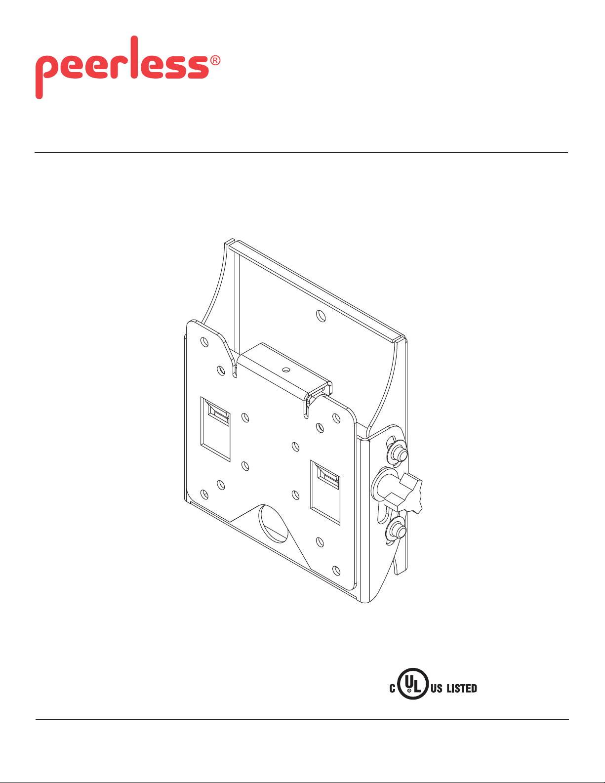
Installation and Assembly: Medical Antimicrobial Universal
Tilt Wall Mount for 22" - 40" (56 - 102 cm) Flat Panel Displays
Models: ST630-AB, ST630-AW
Features:
• Fits 22" - 40" fl at panel displays
• Effortless positioning and adjustment of the display
• Integrated security features provide effective theft deterrence
• Treated with Agion® antimicrobial fi nish in black or white designed to
assist with infection control
2300 White Oak Circle • Aurora, Il 60502 • (800) 865-2112 • Fax: (800) 359-6500 • www.peerlessmounts.com
Max UL Load Capacity: 115 lb (52.2 kg)
ISSUED: 09-20-11 SHEET #: 203-9046-1
Page 2
NOTE: Read entire instruction sheet before you start installation and assembly.
WARNING
• Do not begin to install your Peerless product until you have read and understood the instructions and warnings
contained in this Installation Sheet. If you have any questions regarding any of the instructions or warnings, for US
customers please call Peerless customer care at 1-800-865-2112, for all international customers, please contact
your local distributor.
• This product should only be installed by someone of good mechanical aptitude, has experience with basic building
construction, and fully understands these instructions.
• Make sure that the supporting surface will safely support the combined load of the equipment and all attached
hardware and components.
• Never exceed the Maximum Load Capacity. See page one.
• If mounting to wood wall studs, make sure that mounting screws are anchored into the center of the studs. Use of
an "edge to edge" stud fi nder is highly recommended.
• Always use an assistant or mechanical lifting equipment to safely lift and position equipment.
• Tighten screws fi rmly, but do not overtighten. Overtightening can damage the items, greatly reducing their holding
power.
• This product is intended for indoor use only. Use of this product outdoors could lead to product failure and personal
injury.
• This product was designed to be installed on the following wall construction only;
WALL CONSTRUCTION HARDWARE REQUIRED
• Wood Stud Included
• Wood Beam Included
• Solid Concrete Included
• Cinder Block Included
• Metal Stud Do not attach except with Peerless Metal Stud Accessory Kit - ACC215;
(not evaluated by UL)
• Brick Contact Qualifi ed Professional (not evaluated by UL)
• Other or unsure? Contact Qualifi ed Professional (not evaluated by UL)
Tools Needed for Assembly
• stud fi nder ("edge to edge" stud fi nder is recommended)
• phillips screwdriver
• drill
• 5/16" (8 mm) bit for concrete and cinder block wall
• 5/32" (4 mm) bit for wood stud wall
• level
Table of Contents
Parts List.................................................................................................................................................................................3
Installation to Single Wood Stud Wall .....................................................................................................................................4
Installation to Solid Concrete or Cinder Block ........................................................................................................................5
Attaching Hook Bracket to Display with VESA 75 or 100 Mounting Pattern ...........................................................................6
Installing and Removing Flat Panel Display ...........................................................................................................................7
Recommended Cleaning Guidelines ......................................................................................................................................8
2 of 26
ISSUED: 09-20-11 SHEET #: 203-9046-1
Page 3
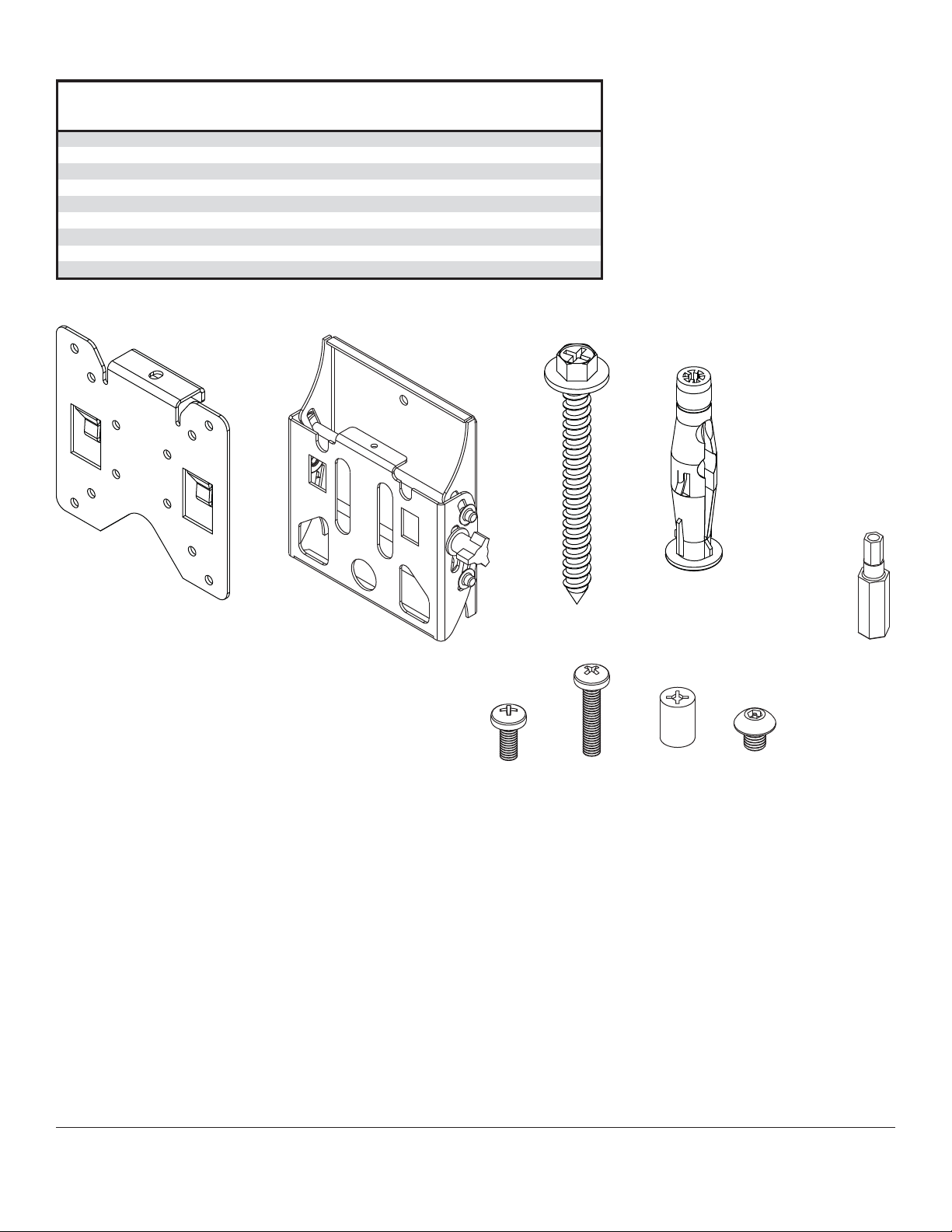
Before you begin, make sure all parts shown are included with your product.
W
A
r
Parts List
Description Qty Part #
hook bracket 1 095-S1346
B tilt assembly 1 095-S1359
C #14 x 2.5" hex head wood screw 2 5S1-015-C03
D concrete anchor 2 590-0320 590-0320
E M4 x 10 mm phillips screw 4 504-9012
F M4 x 20 mm phillips screw 4 504-9020 504-9020
G retaining spacer 4 590-5005
H M5 x 6 mm socket pin screw 1 520-1114 520-1114
I 4 mm securtiy drive
Parts may appear slightly different than illustrated.
ST630-AB
1 560-1133 560-1133
ST630-A
Part #
095-S2346
095-S2360
5S1-015-C03
504-9012
590-5005
A
B
C
D
I
FGE
H
3 of 26
ISSUED: 09-20-11 SHEET #: 203-9046-1
Page 4
Installation to Single Wood Stud Wall
WARNING
• Installer must verify that the supporting surface will safely support the combined load of the equipment and all
attached hardware and components.
• Tighten wood screws so that wall plate is fi rmly attached, but do not overtighten. Overtightening can damage the
screws, greatly reducing their holding power.
• Never tighten in excess of 80 in. • lb (9 N.M.).
• Make sure that mounting screws are anchored into the center of the stud. The use of an "edge to edge" stud fi nder
is highly recommended.
• Hardware provided is for attachment of mount through standard thickness drywall or plaster into wood studs.
Installers are responsible to provide hardware for other types of mounting situations (not evaluated by UL).
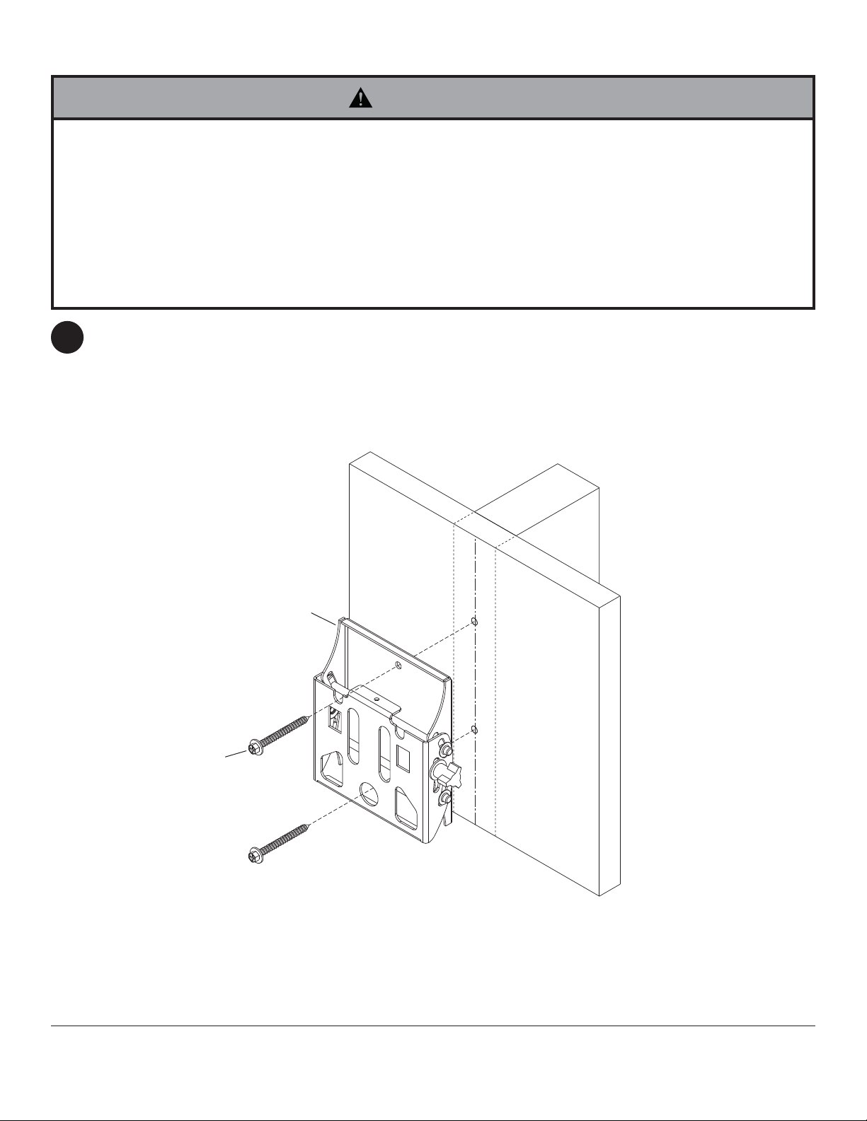
Use a stud fi nder to locate the edges of the stud. Use of an edge-to-edge stud fi nder is highly recommended.
1
Based on its edges, draw a vertical line down the stud’s center. Place tilt assembly (B) on wall as a template,
making sure that the two mounting holes are over the stud centerline. Level tilt assembly, and mark the center of
the two holes. Drill two 5/32" (4 mm) dia. holes 2.5" (64 mm) deep. Make sure that the tilt assembly is level, secure
it using two #14 x 2.5" wood screws (C) as shown.
Skip to step 2.
C
B
4 of 26
ISSUED: 09-20-11 SHEET #: 203-9046-1
Page 5
Installation to Solid Concrete or Cinder Block
WARNING
• When installing Peerless wall mounts on cinder block, verify that you have a minimum of 1-3/8" (35 mm) of actual
concrete thickness in the hole to be used for the concrete anchors. Do not drill into mortar joints! Be sure to mount
in a solid part of the block, generally 1" (25 mm) minimum from the side of the block. Cinder block must meet ASTM
C-90 specifi cations. It is suggested that a standard electric drill on slow setting is used to drill the hole instead of a
hammer drill to avoid breaking out the back of the hole when entering a void or cavity.
• Concrete must be 2000 psi density minimum. Lighter density concrete may not hold concrete anchor.
• Make sure that the wall will safely support four times the combined load of the equipment and all attached hardware
and components.
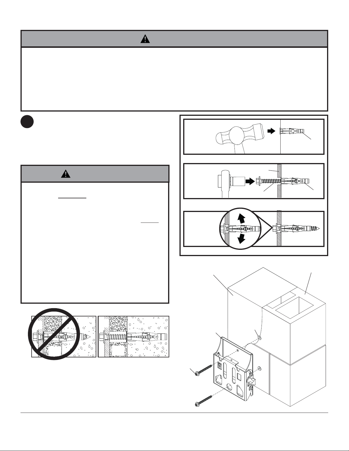
Make sure that tilt assembly (B) is level, use it as a
1
template to mark two mounting holes. Drill two 5/16"
(8 mm) dia. holes to a minimum depth of 2.5"
(64 mm). Insert anchors (D) in holes fl ush with wall
as shown (right). Place tilt assembly over anchors
and secure with two #14 x 2.5" screws (C). Level,
then tighten all fasteners.
1
Drill holes and insert anchors (D).
concrete
surface
D
WARNING
• Tighten screws so that wall plate is fi rmly attached,
but do not overtighten. Overtightening can damage
screws, greatly reducing their holding power.
• Never tighten in excess of 80 in. • lb (9 N.M.).
• Always attach concrete expansion anchors directly
to load-bearing concrete.
• Never attach concrete expansion anchors to
concrete covered with plaster, drywall, or other
fi nishing material. If mounting to concrete surfaces
covered with a fi nishing surface is unavoidable (not
evaluated by UL), the fi nishing surface must be
counterbored as shown below. Be sure concrete
anchors do not pull away from concrete when
tightening screws. If plaster/drywall is thicker than
5/8" (16 mm), custom fasteners must be supplied by
installer (not evaluated by UL).
INCORRECT CORRECT
wall
plate
concrete
wall
plate
concrete
2
B
C
Place plate (B) over anchors (D) and secure with screws (C).
3
Tighten all fasteners.
SOLID CONCRETE
B
D
CINDER BLOCK
D
CUTAWAY VIEW
plaster/
dry wall
plaster/
dry wall
5 of 26
C
ISSUED: 09-20-11 SHEET #: 203-9046-1
Page 6
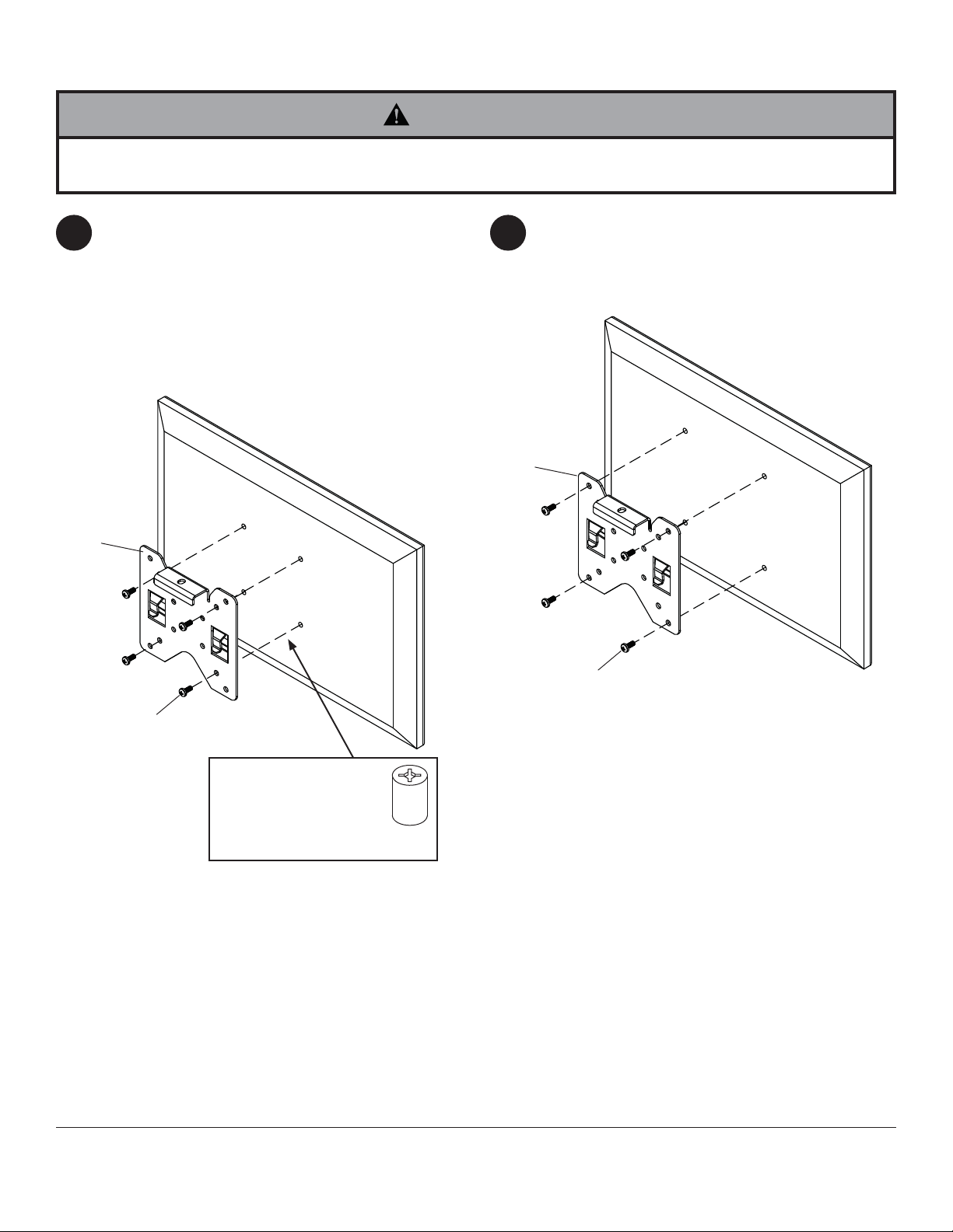
Attaching Hook Bracket to Display with VESA 75 or 100 Mounting Pattern
WARNING
• If screws don't get three complete turns in the display inserts or if screws bottom out and bracket is still not tightly
secured, damage may occur to display or product may fail.
FOR VESA® 75 MOUNTING PATTERN:
2 2
Choose hole pattern as shown below. Attach hook
bracket (A) to back of display using four M4 screws
(E) as shown below.
*NOTE: If hole pattern is in a pocket, attach hook
bracket (A) to back of display using four
M4 x 20 mm screws (F) and four retaining spacers
(G) as indicated below.
A
FOR VESA 100 MOUNTING PATTERN:
Choose hole pattern as shown below. Attach hook
bracket (A) to back of display using four M4 screws
(E) as shown below.
A
E
*For displays with a
hole pattern in a pocket,
spacers (G) go between
hook bracket (A) and
display.
E
G
6 of 26
ISSUED: 09-20-11 SHEET #: 203-9046-1
Page 7
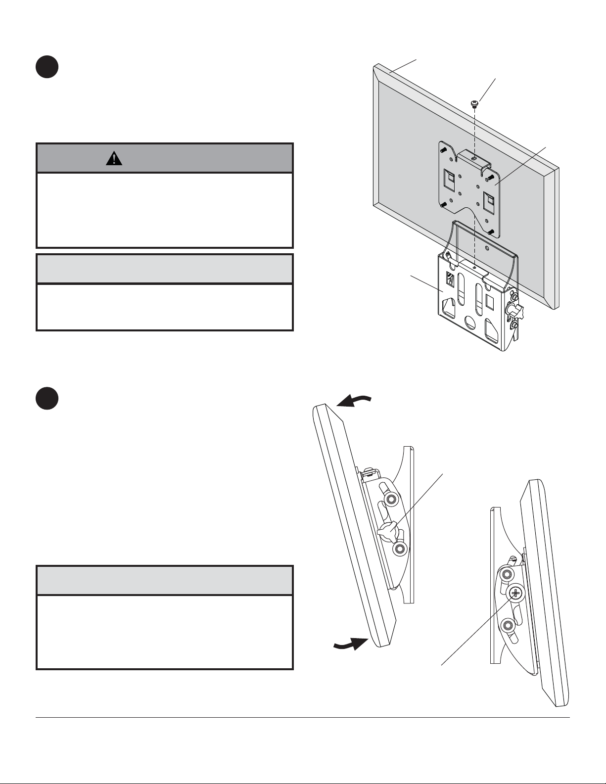
Installing and Removing Flat Panel Display
Attach display to tilt assembly (B). Tighten
3
M5 x 6 mm screw (H) to lock display to tilt assemby.
Tighten M5 x 6 mm socket pin screw (H) using 4
mm security driver (I) to lock display to tilt assemby.
To remove display from mount, loosen M5 screw
(H) and lift display off of mount.
WARNING
• Do not lift more weight than you can handle.
Use additional man power or mechanical lifting
equipment to safely handle placement of the display.
• Failure to lock hook bracket (A) with screw (H) can
cause display to come off mount if hit accidentally.
DISPLAY
H
A
CAUTION
• Do not tighten screws with excessive force.
Overtightening can cause damage to mount. Tighten
screws to 20 in. • lb (2.26 N.M.) maximum torque.
Adjusting the Tilt Angle of the Flat Panel Display
Adjust tension knob on right side of mount shown in
4
fi gure 4.1 to desired tension to balance your display
size and weight.
NOTE: If knob is inaccessible, remove display from
mount, adjust tension knob to desired tension to
balance your display size and weight, and reattach
display to mount as stated in step 3.
Push or pull from top or bottom of display to adjust
tilt as shown in fi gure 4.1. The tilt can be adjusted to
a maximum of 15° forward or 5° backward.
NOTE: To lock the display into the desired tilt
position, tighten tension screw on left side of mount
shown in fi gure 4.2 using phillips screw.
B
fi g. 4.1
TENSION KNOB
fi g. 4.2
CAUTION
• Do not tighten screws with excessive force.
Overtightening can cause damage to mount. Tighten
screws to 40 in. • lb (4.5 N.M.) maximum torque.
• Be careful not to pinch fi ngers when pushing display
from the bottom.
7 of 26
TENSION SCREW
ISSUED: 09-20-11 SHEET #: 203-9046-1
Page 8

Recommended Cleaning Guidelines
The following procedures are not guaranteed to
control infection. An infection control administrator or
epidemiologist should be consulted regarding cleaning
procedures and processes.
Most painted components will withstand cleaning by
commonly used, diluted, non-abrasive solutions such
as quaternary ammonia compounds, ammonia enzyme
cleaners, and bleach or alcohol solutions. However,
it is recommended that any surface be tested in an
inconspicuous area prior to determine the propensity for
discoloration.
• Pen or permanent and dry erase markers can be
removed with 91% isopropyl alcohol and a soft cloth.
• Iodine stains can be removed with commonly used
cleaners and a soft cloth.
• Never use steel wool or other abrasive materials that will
damage the surface fi nish.
• Do not use Acetone, mineral spirits, abrasive cleansers,
paint thinner or any other harsh or toxic chemicals to clean
your product. These solvents will damage the surface
fi nish.
WARNING
• To avoid risk of electric shock, do not expose
electrical components to water, cleaning solutions or
other potentially corrosive liquids or substances.
• Do not use fl ammable cleaners on product surfaces
due to close proximity of electrical power and
equipment.
8 of 26
All other brand and product names are trademarks or registered trademarks of their respective owners.
ISSUED: 09-20-11 SHEET #: 203-9046-1
© 2011, Peerless Industries, Inc. All rights reserved.
Peerless Industries, Inc.
2300 White Oak Circle
Aurora, Il 60502
www.peerlessmounts.com
Page 9

Installation et assemblage: Médico Antimicrobiano
Soporte Universal de pared con Capacidad de Inclinación para
Pantallas Planas de 22" a 40" (56 - 102 cm)
Modelos: ST630-AB, ST630-AW
Características:
• Sostiene pantallas planas de 22" a 40"
• Inclinación de para permitir la colocación y el ajuste de la
pantalla sin esfuerzo
• Funciones integradas de seguridad proporcionan protección
efi ciente contra el robo
• Tratado con Agion
blanco diseñado para ayudar en el control de infecciones
®
acabado médico antimicrobiano negro o
2300 White Oak Circle • Aurora, Il 60502 • (800) 865-2112 • Fax: (800) 359-6500 • www.peerlessmounts.com
Máxima capacidad de UL carga: 115 lb (52.2 kg)
PUBLICADO: 09-20-11 HOJA #: 203-9046-1
Page 10

EspañolEspañol
NOTA: Lea la hoja de instrucciones completa antes de comenzar la instalación y el ensamblaje.
ADVERTENCIA
• No comience a instalar su producto de Peerless hasta haber leído y entendido las instrucciones y las advertencias
contenidas en la Hoja de Instalación. Si tiene alguna pregunta acerca de cualquiera de las instrucciones o las
advertencias, por favor, llame a Servicio al Cliente de Peerless al 1-800-865-2112 si está en EE. UU. Si es un cliente
internacional, por favor, comuníquese con su distribuidor local.
• Este producto sólo debe ser instalado por una persona que tenga una buena aptitud mecánica, que tenga
experiencia en construcción básica de edifi cios y que entienda estas instrucciones en su totalidad.
• Asegúrese de que la superfi cie de apoyo sostendrá, con seguridad, la carga combinada del equipo y todos los
fi jadores y componentes.
• Nunca sobrepase la capacidad máxima de soportar carga. Vea la página 9.
• Si va a instalar el producto en una pared con montantes de madera, asegúrese de que los tornillos de montaje estén
anclados en el centro de los montantes. Se recomienda utilizar un localizador de montantes de "borde a borde".
• Siempre cuente con la ayuda de un asistente o utilice un equipo mecánico de izar para levantar y colocar el equipo
con más seguridad.
• Apriete los tornillos con fi rmeza, pero no en exceso. Apretarlos en exceso puede dañar los artículos y puede
disminuir signifi cativamente su fuerza de fi jación.
• Este producto está diseñado para uso en interiores solamente. Utilizar este producto en exteriores podría causar
fallas del producto y lesiones a individuos.
• Este producto fue diseñado para ser instalado en paredes con la siguiente construcción solamente:
CONSTRUCCIÓN DE LA PARED ACCESORIOS NECESARIOS
• Montante de madera Incluido
• Viga de madera Incluido
• Concreto macizo Incluido
• Bloque de hormigón de escorias Incluido
• Montante de metal No lo instale excepto con el juego de accesorios de Peerless para
montantes de metal - ACC215; (no evaluados por UL)
• Ladrillo Comuníquese con un profesional califi cado (no evaluados por UL)
• ¿Otra superfi cie o no está seguro? Comuníquese con un profesional califi cado (no evaluados por UL)
Herramientas necesarias para el ensamblaje
• localizador de montantes (se recomienda uno de "borde a borde")
• destornillador phillips
• taladro
• broca de 5/16" (8 mm) para paredes de concreto y de bloque de hormigón de escorias
• broca de 5/32" (4 mm) para paredes con montantes de madera
• nivel
Contenido
Lista de piezas...................................................................................................................................................................... 11
Instalación en una pared con montantes de madera ...........................................................................................................12
Instalación en una pared de concreto macizo o de bloques de hormigón de escorias ........................................................13
Fijación de la placa de montaje a pantallas con confi guraciones de montaje VESA® 75 ó 100 .........................................14
Instalación y desinstalación de la pantalla plana .................................................................................................................15
Recomendaciones para la limpieza......................................................................................................................................16
10 de 26
PUBLICADO: 09-20-11 HOJA #: 203-9046-1
Page 11

Antes de comenzar, asegúrese de que su producto contiene todas las piezas que se muestran.
W
A
m
EspañolEspañol
Lista de Piezas
Descripción Cant. N.° de pieza N.° de pieza
soporte de gancho 1 095-S1346
B inclinación de montaje 1 095-S1359
C tornillo para madera de 14 x 2.5" 2 5S1-015-C03
anclaje para concreto 2 590-0320 590-0320
D
E tornillo phillips M4 x 10 mm 4 504-9012
F tornillo phillips M4 x 20 mm 4 504-9020 504-9020
G espaciador de retención 4 590-5005
H tornillo de cabeza hueca de M5 x 6 mm 1 520-1114 520-1114
I destornillador de seguridad de 4 m
Algunas partes pueden diferir un poco de las ilustradas.
ST630-AB
1 560-1133 560-1133
ST630-A
095-S2346
095-S2360
5S1-015-C03
504-9012
590-5005
A
B
C
D
I
FGE
H
11 de 26
PUBLICADO: 09-20-11 HOJA #: 203-9046-1
Page 12

EspañolEspañol
Instalación en una pared con montantes de madera
ADVERTENCIA
• El instalador tiene que asegurarse de que la superfi cie de apoyo sostendrá, con seguridad, la carga combinada del equipo y todos
los fi jadores y componentes.
• Apriete los tornillos de madera de manera que la placa de pared se fi je fi rmemente, pero no en exceso. Apretarlos en exceso
puede dañar los tornillos y puede disminuir signifi cativamente su fuerza de fi jación.
• Nunca apriete a más de 80 pulg-lb (9 N•m).
• Asegúrese de que los tornillos de montaje estén anclados en el centro del montante. Se recomienda utilizar un localizador de
montantes de "borde a borde".
• Los accesorios para la instalación que se proveen son para fi jar el soporte a montantes de madera a través de tabique de yesocartón o yeso de espesor estándar. Los instaladores son responsables de suministrar los accesorios necesarios para otros tipos
de instalaciones
Utilice un localizador de montantes para localizar los bordes del montante. Se recomienda utilizar un localizador de
1
montantes de “borde a borde”. Tomando los bordes como punto de referencia, trace una línea vertical por el centro
del montante. Coloque la unidad de inclinación (B) en la pared para utilizarla como plantilla; asegúrese de que
los dos agujeros de montaje estén sobre la línea que trazó por el centro. Nivele la unidad de inclinación y marque
el centro de los dos agujeros. Taladre dos agujeros de 5/32" (4 mm) de diámetro y 2.5" (64 mm) de profundidad.
Asegúrese de que la unidad de inclinación esté nivelada, fíjela utilizando dos tornillos para madera de 14 x 2.5"
(C), como se muestra.
Pase al paso 2.
(no evaluados por UL).
C
B
12 de 26
PUBLICADO: 09-20-11 HOJA #: 203-9046-1
Page 13

Instalación en una pared de concreto macizo o de bloques de hormigón
EspañolEspañol
de escorias
ADVERTENCIA
• Cuando vaya a instalar soportes de pared de Peerless en bloques de hormigón de escorias, asegúrese de que cuente con una
capa de concreto de un grosor mínimo de 1-3/8" en el agujero, que pueda usar para los anclajes para concreto. ¡No taladre en
juntas de argamasa! Asegúrese de hacer la instalación en la parte sólida del bloque, por lo general, a un mínimo de 1" (25 mm) del
extremo del bloque. Los bloques de hormigón de escorias tienen que cumplir las especifi caciones de la ASTM C-90. Se sugiere
utilizar un taladro eléctrico convencional a baja velocidad para hacer el agujero en vez de un taladro percutor para no perforar el
fondo del agujero al entrar en un vacío o una cavidad.
• El concreto tiene que tener una densidad mínima de 2,000 psi. Es posible que un concreto de menos densidad no sostenga el
anclaje para concreto.
• Asegúrese de que la superfi cie de apoyo sostendrá, con seguridad, la carga combinada del equipo y todos los fi jadores y
componentes.
Asegúrese de que la unidad de inclinación (B) esté
1
nivelada y utilícela como plantilla para marcar dos
agujeros de montaje. Taladre dos agujeros de 5/16"
(8 mm) de diámetro a una profundidad mínima
de 2.5" (64 mm). Inserte los anclajes (D) en los
agujeros a ras con la pared, como se muestra (a la
derecha). Coloque la unidad de inclinación sobre
los anclajes y fíjela con dos tornillos de 14 x 2.5"
(C). Nivele y apriete todos los sujetadores.
ADVERTENCIA
• Apriete los tornillos de manera que la placa de pared
se fi je fi rmemente, pero no en exceso. Apretarlos en
exceso puede dañar los tornillos y puede disminuir
signifi cativamente su fuerza de fi jación.
• Nunca apriete a más de 80 pulg-lb (9 N•m).
• Siempre fi je los anclajes para concreto directamente en la
pared que sostiene la carga.
• Nunca fi je los anclajes para concreto a una pared de concreto
recubierta con yeso, tabique de yeso-cartón u otro material de
acabado. Si es inevitable hacer la instalación en una superfi cie
de concreto recubierta con una superfi cie de acabado
evaluados por UL), la superfi cie de acabado tiene que ser
escariada, como se muestra abajo. Asegúrese de que los
anclajes para concreto no se separen del concreto cuando
apriete los tornillos. Si el grosor de la capa de yeso o tabique
de yeso-cartón tiene un grosor mayor de 5/8", el instalador
tiene que suministrar las fi jaciones especiales
por UL).
INCORRECTO
(no evaluados
(no
CORRECTO
1
Perfore los agujeros y después inserte los anclajes (D).
2
B
C
Coloque la placa (B) sobre los anclajes (D) y fíjela con
los tornillos (C).
3
Apriete todas las fi jaciones.
CONCRETO MACIZO
D
superfi cie de
concreto
D
D
BLOQUE DE
HORMIGÓN
DE ESCORIAS
placa
de
pared
VISTA EN CORTE
concreto
yeso / tabique de yeso-cartón
placa
pared
de
concreto
13 de 26
B
C
PUBLICADO: 09-20-11 HOJA #: 203-9046-1
Page 14

EspañolEspañol
Fijación del soporte de gancho a pantallas con confi guraciones de
montaje VESA® 75 ó 100
ADVERTENCIA
• Si no se les da tres vueltas completas a los tornillos en los insertos de la pantalla o si los tornillos topan fondo y el
soporte todavía no está fi rme, se podría dañar la pantalla o el producto podría no funcionar bien.
EN EL CASO DE LA CONFIGURACIÓN DE
2 2
MONTAJE VESA® 75:
Escoja un patrón de agujeros, como se muestra
abajo. Fije la soporte de gancho (A) a la parte
trasera de la pantalla usando cuatro tornillos de
M4 (E), como se muestra abajo.
*Nota: Si la confi guración de agujeros está en una
cavidad, fi je la placa de montaje (A) en la parte
trasera de la pantalla usando cuatro tornillos de
M4 x 20 mm (F) y cuatro espaciadores de etención
(G), como se indica abajo.
A
EN EL CASO DE LA CONFIGURACIÓN DE
MONTAJE VESA® 100:
Escoja un patrón de agujeros, como se muestra
abajo. Fije la soporte de gancho (A) a la parte
trasera de la pantalla usando cuatro tornillos de
M4 (E), como se muestra abajo.
A
E
*En el caso de las pantallas que
tienen la confi guración de agujeros
en una cavidad, los espaciadores (G)
van entre el soporte de gancho (A) y
la pantalla.
G
14 de 26
E
PUBLICADO: 09-20-11 HOJA #: 203-9046-1
Page 15

Instalación y desinstalación de la pantalla plana
Fije la pantalla en la unidad de inclinación (B).
3
Apriete el tornillo de M5 x 6 mm (H) para fi jar la
pantalla en la unidad de inclinación.
Apriete el tornillo pasador de cabeza hueca de
M5 x 6 mm (H) con un destornillador de seguridad
de 4 mm (I) para fi jar la pantalla en la unidad de
inclinación.
Para quitar la pantalla del soporte, afl oje el tornillo
(H) y levante la pantalla para sacarla del soporte.
ADVERTENCIA
• No levante más peso del que puede manejar. Cuente con
otra persona que lo ayude o utilice un equipo mecánico de
izar para levantar y colocar la pantalla con seguridad.
• No trabar el soporte de gancho (A) con el tornillo (H) puede
causar que la pantalla se caiga del soporte si recibe un
golpe accidental.
ATENCIÓN
EspañolEspañol
PANTALLA
H
A
B
• No apriete los tornillos con fuerza excesiva. Apretarlos en
exceso puede dañar el soporte. Apriete los tornillos a un
máximo de 20 pulg-lb (2.26 N•m) de par torsor.
Ajuste del ángulo de inclinación de la pantalla de panel plano
Ajuste la perilla de tensión que se encuentra en el
4
lado del soporte que se muestra en la fi gura 4.1
al grado de tensión deseado para balancear el
tamaño y el peso de la pantalla.
NOTA: Si mando es inaccesible, quitar la pantalla
de montar, ajustar la tensión de mando de la
tensión deseada para equilibrar su peso y tamaño
de pantalla, pantalla y volver a montar como se
indica en el paso 3 Mueva la parte superior o la
parte inferior de la pantalla tirando de la misma o
empujándola para ajustar la inclinación, como se
muestra. La inclinación se puede ajustar hasta un
máximo de 15° hacia delante o de 5° hacia atrás.
NOTA: Para bloquear la pantalla en la posición de
la inclinación deseada, apriete el tornillo de tensión
en el lado izquierdo de montaje se muestra en la
fi gura 4.2 utilizando el tornillo phillips.
fi g. 4.1
PERILLA DE TENSIÓN
fi g. 4.2
ATENCIÓN
• No apriete los tornillos con fuerza excesiva. Apretarlos en
exceso puede dañar el soporte. Apriete los tornillos a un
máximo de 40 pulg-lb (4.5 N•m) de par torsor.
• Tenga cuidado de no pincharse los dedos cuando extienda y
recoja el soporte contra la pared.
15 de 26
TORNILLO DE TENSIÓN
PUBLICADO: 09-20-11 HOJA #: 203-9046-1
Page 16

Recomendaciones para la limpieza
No se garantiza que los siguientes procedimientos
controlarán las infecciones. Se debe consultar a un
manejador de control de infecciones o un epidemiólogo
respecto a los procedimientos y procesos de limpieza.
La mayoría de los componentes pintados resistirán la
limpieza con soluciones sin abrasivos diluidas de uso
común como los compuestos de amoniaco cuaternario,
limpiadores con enzimas de amoniaco y soluciones con
blanqueador o alcohol. Sin embargo, se recomienda que
se haga una prueba en un área discreta de la superfi cie
antes de determinar la propensión a descolorarse.
• Las marcas de bolígrafo o marcadores permanentes
y de borrado en seco se pueden eliminar con alcohol
isopropílico al 91% y un paño suave.
• Las manchas de yodo se pueden eliminar con
limpiadores de uso común y un paño suave.
• No use esponjas de acero ni otros materiales abrasivos
que puedan dañar el acabado de la superfi cie.
• No use acetona, alcoholes minerales, limpiadores
abrasivos, solvente de pintura ni ningún otro químico
áspero o tóxico para limpiar el producto. Estos solventes
dañarán el acabado de la superfi cie.
EspañolEspañol
ADVERTENCIA
• Para evitar el riesgo de choque eléctrico, no
exponga los componentes eléctricos al agua,
a soluciones limpiadoras ni a otros líquidos o
sustancias potencialmente corrosivos.
• No use limpiadores infl amables en las superfi cies
del producto debido a la proximidad a tomas de
corriente y otros equipos eléctricos.
16 de 26
Cualesquiera otras marcas y nombres de productos son marcas comerciales o registradas de sus respectivos dueños.
PUBLICADO: 09-20-11 HOJA #: 203-9046-1
© 2011, Peerless Industries, Inc. Todos los derechos reservados.
Peerless Industries, Inc.
2300 White Oak Circle
Aurora, Il 60502
www.peerlessmounts.com
Page 17

Installation et Montage: Médicaux Antimicrobien Support
mural inclinable universel pour écrans plats de 22 à 40 po
(56 - 102 cm)
Modèles: ST630-AB, ST630-AW
Caractéristiques:
• Convient aux écrans plats de 22 à 40 po
• Inclinaison par simple appui sur un réglage et un
positionnement faciles de l’écran
• Fonctions sécuritaires intégrées procurant une
dissuasion effi cace contre le vol
• Traité avec Agion
blanc conçu pour aider à prévenir les infections.
®
fi ni médicaux antimicrobien noir ou
2300 White Oak Circle • Aurora, Il 60502 • (800) 865-2112 • Fax: (800) 359-6500 • www.peerlessmounts.com
Capacité de charge maximale UL préconisée: 115 lb (52.2 kg)
PUBLIÉ LE: 09-20-11 FEUILLE no: 203-9046-1
Page 18

Français
REMARQUE: lisez entièrement la fi che d’instructions avant de commencer l’installation et l’assemblage.
AVERTISSEMENT
• Ne commencez pas à installer votre produit Peerless avant d’avoir lu et assimilé les instructions et les avertissements
contenus dans cette fi che d’installation. Pour toute question concernant les instructions ou les avertissements,
veuillez appeler le service à la clientèle de Peerless au 1-800-865-2112; tous les clients internationaux sont priés de
contacter leur distributeur local.
• Ce produit doit être installé uniquement par quelqu’un possédant une bonne aptitude à la mécanique, une expérience
de la construction immobilière et ayant bien compris ces instructions.
• Assurez-vous que la surface de support puisse soutenir sans danger la charge totale de l’équipement ainsi que des
pièces et composants qui y sont attachés.
• Ne dépassez jamais la capacité de charge maximum. Reportez-vous à la page 17.
• Lors d’une installation sur un mur à montants en bois, assurez-vous que les vis de montage sont ancrées au centre
des montants. L’utilisation d’un localisateur de montants « bord à bord » est fortement recommandée.
• Pour lever et positionner l’équipement en toute sécurité, faites-vous toujours aider par une autre personne ou utilisez
un dispositif de levage mécanique.
• Serrez fermement les vis, mais sans excès. Un serrage excessif peut endommager les composants et en réduire
considérablement la capacité de support.
• Ce produit est conçu uniquement pour un usage intérieur. L’utilisation de ce produit à l’extérieur peut causer une
défaillance du produit et des blessures corporelles.
• Ce produit a été conçu uniquement pour une installation sur les types de murs ci-dessous :
TYPE DE MUR PIÈCES DE FIXATION REQUISES
• Montant en bois Incluses
• Poutre en bois Incluses
• Béton plein Incluses
• Bloc de béton de mâchefer Incluses
• Montant métallique Ne pas installer sur ce type de mur sauf à l’aide de l’ensemble d’accessoires
Peerless pour montants métalliques - ACC215; (non évalué UL)
• Brique Contacter un professionnel qualifi é (non évalué UL)
• Autre, ou vous n’êtes pas sûr ? Contacter un professionnel qualifi é (non évalué UL)
Outils nécessaires au montage
• localisateur de montants (un localisateur de montants « bord à bord » est recommandé)
• tournevis phillips
• perceuse
• foret de 5/32 po (4 mm) pour les murs à montants en bois
• foret de 5/16 po (8 mm) pour les murs à block de béton
• niveau
Tabla de contenido
Lista de piezas......................................................................................................................................................................19
Installation sur un mur a simple montant en bois ................................................................................................................. 20
Installation sur du béton plein ou un bloc de béton de mâchefer ......................................................................................... 21
Fixation d’un crochet de support sur un écran à confi guration de montage VESA 75 ou 100 .............................................22
Installation de l’écran plat sur la plaque murale ...................................................................................................................23
Méthodes de nettoyage recommandées ............................................................................................................................. 24
18 sur 26
PUBLIÉ LE: 09-20-11 FEUILLE n°: 203-9046-1
Page 19

Avant de commencer, veillez à ce que toutes les pièces énumérées soient incluses.
W
p
A
m
Français
Liste des pièces
Description Qté
Crochet de support 1 095-S1346
B ensemble d’inclinaison 1 095-S1359
C vis à bois no 14 x 2,5 po 2 5S1-015-C03
chevilles d'ancrage pur béton 2 590-0320 590-0320
D
E vis cruciforme M4 x 10 mm 4 504-9012
F vis cruciforme M4 x 20 mm 4 504-9020 504-9020
G entretoise de retenue 4 590-5005
H vis à tête creuse M5 x 6 mm 1 520-1114 520-1114
I embout de sécurité de 4 m
Les pièces peuvent différer légèrement de l’illustration.
ST630-AB
ièces no
1 560-1133 560-1133
o
ST630-A
pièces no
095-S2346
095-S2360
5S1-015-C03
504-9012
590-5005
o
A
B
C
D
I
FGE
H
19 sur 26
PUBLIÉ LE: 09-20-11 FEUILLE n°: 203-9046-1
Page 20

Français
Installation sur un mur à montant en bois
AVERTISSEMENT
• L’installateur doit s’assurer que la surface de support pourra soutenir sans danger la charge combinée de l’équipement, de toute
sa visserie et de tous ses composants.
• Serrez les vis à bois de manière que la plaque murale soit fermement fi xée, mais sans excès. Un serrage excessif peut
endommager les vis et en réduire considérablement le pouvoir de maintien.
• Ne serrez jamais à plus de 9 Nm (80 po-lb).
• Assurez-vous que les vis de montage sont ancrées au centre des montants. L’usage d’un localisateur de montants
« bord à bord » est fortement conseillé.
• La visserie est fournie pour fi xer la monture à travers une cloison sèche ou du plâtre d’épaisseur standard et dans des montants
en bois. Il appartient aux installateurs de fournir la visserie nécessaire pour d’autres types de situations (non évalué UL).
Utilisez un localisateur de montants pour repérer les bords du montant. L’usage d’un localisateur bord à bord est
1
fortement conseillé. En fonction de ses bords, tracez une ligne verticale le long du centre du montant. Utilisez
l’ensemble d’inclinaison (B) comme gabarit et placez-le sur le mur, en vous assurant que les deux trous de
montage se trouvent sur l’axe du montant. Mettez l’ensemble d’inclinaison de niveau et marquez le centre des trois
trous. Percez deux trous de 4 mm (5/32 po) de diamètre et de 64 mm (2,5 po) de profondeur. Assurez-vous que
l’ensemble d’inclinaison est de niveau, fi xez-le à l’aide de deux vis à bois nº 14 x 2,5 po (C), comme illustré.
Passez à l’étape 2.
C
B
20 sur 26
PUBLIÉ LE: 09-20-11 FEUILLE n°: 203-9046-1
Page 21

Français
Installation sur du béton plein ou un bloc de béton de mâchefer
AVERTISSEMENT
• Si vous installez des montures murales Peerless sur un bloc de béton de mâchefer, vérifi ez que vous disposez d’une épaisseur
de béton d’au moins 0,34 cm (1 3/8 po) dans le trou destiné aux ancrages de béton. Ne percez pas dans les joints de mortier !
Veillez à effectuer le montage dans une partie pleine du bloc, généralement à au moins 2,5 cm (1 po) du côté du bloc. Le bloc de
béton de mâchefer doit être conforme aux spécifi cations de l’ASTM C-90. Pour percer le trou, il est conseillé d’utiliser une perceuse
électrique standard sur un réglage bas au lieu d’un marteau perforateur, afi n d’éviter de briser la partie arrière du trou lorsque vous
pénétrez un vide ou une cavité.
• Le béton doit avoir une densité minimale de 2 000 psi. Un béton de densité moindre risquerait de ne pas retenir un ancrage de
béton.
• Assurez-vous que la surface de support pourra soutenir sans danger la charge combinée de l’équipement, de toute sa visserie et
de tous ses composants.
Assurez-vous que l’ensemble d’inclinaison (B) est
1
de niveau, utilisez-le comme gabarit pour marquer
les deux trous de montage. Percez deux trous
de 8 mm (5/16 po) de diamètre à une profondeur
minimum de 64 mm (2,5 po). Insérez les ancrages
(D) dans les trous au ras du mur, comme illustré
(à droite). Placez l’ensemble d’inclinaison sur les
ancrages et fi xez-le à l’aide de deux vis nº 14 x 2,5
po (C). Mettez-le de niveau, puis serrez toutes les
fi xations.
AVERTISSEMENT
• Serrez les vis de manière que la plaque murale soit
fermement fi xée, mais sans excès. Un serrage excessif
peut endommager les vis et en réduire considérablement le
pouvoir de maintien.
• Ne serrez jamais à plus de 9 Nm (80 po-lb).
• Fixez toujours des ancrages de béton directement sur du
béton porteur.
• Ne fi xez jamais d’ancrages sur du béton recouvert de plâtre,
une cloison sèche ou autre matériau de fi nition. Si vous
ne pouvez pas éviter d’effectuer le montage sur du béton
recouvert d’une surface de fi nition (non évalué UL), celle-ci
doit être chambrée, comme indiqué ci-dessous. Assurezvous que les ancrages de béton ne se séparent pas du
béton lorsque vous serrez les vis. Si l’épaisseur du plâtre /
de la cloison sèche dépasse 1,5 cm (5/8 po), des fi xations
adaptées devront être fournies par l’installateur (non évalué
UL).
1
surface en
béton
D
Percez des trous et insérez les ancrages (D).
2
B
C
Placez la plaque (B) sur les ancrages (D) et fi xez avec des vis (C).
3
Serrez toutes les fi xations.
BLOC DE BÉTON
BÉTON PLEIN
DE MÂCHEFER
D
plaque
mural
plâtre /
VUE EN COUPE
cloison sèche
INCORRECT
béton
plaque
mural
plâtre /
cloison sèche
CORRECT
béton
21 sur 26
D
B
C
PUBLIÉ LE: 09-20-11 FEUILLE n°: 203-9046-1
Page 22

Français
Fixation d’un crochet de support sur un écran à confi guration de
montage VESA 75 ou 100
ADVERTISSEMENT
• Si les vis ne sont pas enfoncées de trois tours complets dans les inserts ou si elles sont serrées au maximum sans
parvenir à fi xer solidement la plaque adaptatrice, l’écran peut être abîmé ou le produit détérioré.
CONFIGURATION DE MONTAGE VESA® 75 :
2 2
Choisissez la confi guration de trous illustrée
cidessous. Fixez le crochet de support (A) à l’arrière
de l’écran à l’aide de quatre vis M4 (E), comme
illustré ci-dessous.
*Remarque : Si les trous sont disposés en poche,
fi xez le crochet de support (A) à l’arrière de
l’écran à l’aide de quatre vis M4 x 20 mm (F) et de
quatre entretoises de retenue (G), comme indiqué
cidessous.
A
CONFIGURATION DE MONTAGE VESA 100:
Choisissez la confi guration de trous illustrée
cidessous. Fixez le crochet de support (A) à l’arrière
de l’écran à l’aide de quatre vis M4 (E), comme
illustré ci-dessous.a
A
E
*Pour les écrans comportant
des trous disposés en poche,
les entretoises (G) se placent
entre le crochet de support (A)
et l’écran.
G
22 sur 26
E
PUBLIÉ LE: 09-20-11 FEUILLE n°: 203-9046-1
Page 23

Montage et démontage d’un écran plat
Fixez l’écran sur l’ensemble d’inclinaison (B).
3
Serrez la vis M5 x 6 mm (H) pour fi xer l’écran sur
l’ensemble d’inclinaison.
Serrez la vis à tête creuse M5 x 6 mm (H) à l’aide
de l’embout de sécurité (I), ce qui fi xera l’écran
sur l’ensemble d’inclinaison. Pour retirer l’écran du
support, desserrez la vis (H) et soulevez-le hors du
support.
ADVERTISSEMENT
• Ne soulevez pas plus de poids que vous ne pouvez en
manipuler. Faites-vous aider ou utilisez un équipement
mécanique pour placer l’écran en toute sécurité.
• Si les crochets de support (A) ne sont pas fi xés avec la
vis (H), l’écran pourrait tomber du support, s’il est heurté
accidentellement.
ATTENTION
Français
ÉCRAN
H
A
B
• N’employez pas une force excessive pour serrer les vis.
Un serrage excessif peut endommager le support. Serrez
les vis à un couple maximum de 2,26 Nm (20 po-lb).
Réglage de l’inclinaison d’un écran plat
Réglez le bouton situé sur le côté droit du support
4
illustré sur la fi gure 4.1 à la tension désirée pour
équilibrer la taille et le poids de l’écran.
Remarque : Si le bouton est inaccessible, enlevez
l’écran du support, réglez le bouton sur la tension
désirée pour équilibrer la taille et le poids de l’écran
et remettez l’écran sur le support comme indiqué à
l’étape 3.
Poussez ou tirez depuis le haut ou le bas de l’écran
pour régler l’inclinaison, comme illustré à la fi gure
4.1. L’inclinaison peut être réglée à un maximum de
15° à l’avant ou 5° à l’arrière.
Remarque : Pour verrouiller l’écran dans la position
d’inclinaison désirée, serrez la vis de tension située
sur le côté gauche du support illustré à la fi gure 4.2
à l’aide d’un tournevis cruciforme.
fi g. 4.1
BOUTON DE
TENSION
fi g. 4.2
ATTENTION
• N’employez pas une force excessive pour serrer les vis. Un
serrage excessif peut endommager le support. Serrez les
vis à un couple maximum de 4,5 Nm (40 po-lb).
• Prenez garde à ne pas vous pincer les doigts lorsque vous
poussez l’écran depuis le bas.
23 sur 26
VIS DE TENSION
PUBLIÉ LE: 09-20-11 FEUILLE n°: 203-9046-1
Page 24

Méthodes de nettoyage recommandées
Les procédures suivantes ne garantissent pas la
prévention des infections. Il convient de consulter un
administrateur de la prévention des infections ou un
épidémiologiste concernant les procédures et processus
de nettoyage.
La plupart des composants peints résistent au nettoyage
avec des solutions non abrasives courantes, sous forme
diluée, telles que : composés d’ammonium quaternaire,
nettoyants enzymatique à base d’ammoniac, eau de
Javel ou autres solutions à base d’alcool. Il est toutefois
conseillé de faire un essai préalable sur une partie peu
visible afi n de déterminer la tendance à la décoloration.
• Les marques de stylo ou de marqueurs permanents et
à essuyage à sec peuvent être éliminées à l’aide d’alcool
isopropylique à 91% et d’un chiffon doux.
• Les taches d’iode peuvent être éliminées à l’aide de
nettoyants courants et d’un chiffon doux.
• Ne jamais utiliser de laine d’acier ni d’autres matériaux
abrasifs susceptibles d’endommager le fi ni de la surface.
• Ne pas utiliser d’acétone, d’essences minérales, de
nettoyants abrasifs, de diluant pour peintures ni aucun
produit chimique toxique ou puissant pour nettoyer votre
produit. Ces solvants endommagent le fi ni de la surface.
Français
AVERTISSEMENT
• Pour éviter le risque de choc électrique, ne pas
exposer les composants électriques à l’eau, à des
solutions de nettoyage ni à d’autres liquides ou
substances potentiellement corrosifs.
• Ne pas utiliser de nettoyants infl ammables sur les
surfaces du produit en raison de la proximité de
l’alimentation et de l’équipement électriques.
24 sur 26
Tous les autres noms de marques et de produits sont des marques de commerce ou déposées de leurs propriétaires respectifs.
PUBLIÉ LE: 09-20-11 FEUILLE n°: 203-9046-1
© 2011, Peerless Industries, Inc. Tous droits réservés.
Peerless Industries, Inc.
2300 White Oak Circle
Aurora, Il 60502
www.peerlessmounts.com
Page 25

LIMITED FIVE-YEAR WARRANTY
Peerless Industries, Inc. (“Peerless”) warrants to original end-users of Peerless® products will be free from defects in material and workmanship, under normal
use, for a period of fi ve years from the date of purchase by the original end-user (but in no case longer than six years after the date of the product’s manufacture).
In no event shall the duration of any implied warranty of merchantability or fi tness for a particular purpose be longer than the period of the applicable
express warranty set forth above. Some states do not allow limitations on how long an implied warranty lasts, so the above limitation may not apply to you.
This warranty does not cover damage caused by (a) service or repairs by the customer or a person who is not authorized for such service or repairs by Peerless,
(b) the failure to utilize proper packing when returning the product, (c) incorrect installation or the failure to follow Peerless’ instructions or warnings when installing,
In no event shall Peerless be liable for incidental or consequential damages or damages arising from the theft of any product, whether or not secured
by a security device which may be included with the Peerless® product. Some states do not allow the exclusion or limitation of incidental or consequential
This warranty is in lieu of all other warranties, expressed or implied, and is the sole remedy with respect to product defects. No dealer, distributor, installer or other
person is authorized to modify or extend this Limited Warranty or impose any obligation on Peerless in connection with the sale of any Peerless® product.
At its option, Peerless will repair or replace, or refund the purchase price of, any product which fails to conform with this warranty.
using or storing the product, or (d) misuse or accident, in transit or otherwise, including in cases of third party actions and force majeure.
damages, so the above limitation or exclusion may not apply to you.
This warranty gives specifi c legal rights, and you may also have other rights which vary from state to state.
www.peerlessmounts.com
© 2011, Peerless Industries, Inc.
Español
GARANTÍA LIMITADA DE CINCO AÑOS
Peerless Industries, Inc. (Peerless) les garantiza a los usuarios fi nales originales de los productos Peerless® que los productos Peerless® estarán libres de
defectos de materiales o de manufactura, en condiciones de uso normal, durante un periodo de cinco (5) años a partir de la fecha en la que el usuario fi nal
original compre cualquier producto (pero, en ningún caso, durante un periodo mayor de 6 años después de la fecha de manufactura del producto). Queda a la
La duración de toda garantía implícita de comerciabilidad o de idoneidad para un propósito en particular no sobrepasará en caso alguno el periodo
de vigencia de la garantía explícita correspondiente indica en lo anterior. Algunos Estados no permiten que se establezcan limitaciones en relación con el
Esta garantía no cubre daños causados por (a) trabajos de mantenimiento o de reparación hechos por el cliente o alguna persona que no esté autorizada por
Peerless para realizar dichos trabajos de mantenimiento o de reparación, (b) no empacar el producto como es debido si lo devuelve, (c) hacer una instalación
incorrecta o no seguir las instrucciones o las advertencias de Peerless al instalar, utilizar o guardar el producto o (d) el mal uso o los accidentes, en tránsito o en
Peerless no tendrá responsabilidad en ningún caso de daños y perjuicios incidentales o indirectos o de daños y perjuicios que surjan por el robo de
cualquier producto, ya sea que el mismo esté o no esté asegurado con un dispositivo de seguridad que se haya incluido con el producto de Peerless®.
Algunos Estados no permiten que se excluyan o se establezcan limitaciones en relación con los daños y perjuicios incidentales o indirectos, de manera que es
Esta garantía remplaza toda otra garantía, expresa o implícita, y es el único recurso en lo que respecta a los defectos del producto. Ningún concesionario,
distribuidor, instalador ni ninguna otra persona está autorizada a modifi car o extender esta Garantía Limitada ni a imponer obligación alguna a Peerless en
Esta garantía concede derechos específi cos creados por ley y es posible que usted, además, tenga otros derechos que varían de acuerdo con el Estado donde
discreción de Peerless, reparar, reemplazar o rembolsar el precio de compra de cualquier producto que no cumpla esta garantía.
periodo de duración de una garantía implícita, de manera que es posible que la limitación expuesta en lo anterior no sea pertinente a usted.
otras circunstancias, incluidos los casos relacionados con las acciones de terceros o una fuerza mayor.
posible que la limitación o la exclusión expuesta en lo anterior no sea pertinente a usted.
relación con la venta de cualquier producto de Peerless®.
se encuentre.
www.peerlessmounts.com
25 of 26
© 2011, Peerless Industries, Inc.
ISSUED: 09-20-11 SHEET #: 203-9046-1
Page 26

Français
GARANTIE DE CINQ ANS
Peerless Industries, Inc. (« Peerless ») garantit aux utilisateurs fi naux d’origine des produits PeerlessMD que lesdits produits ne présenteront aucun défaut de
matériau ou de main-d’œuvre, dans la mesure où ils sont utilisés normalement, pendant une période de cinq ans à compter de la date d’achat par l’utilisateur fi nal
d’origine (mais en aucun cas plus de six ans après la date de fabrication du produit). Peerless, à sa discrétion, réparera ou remplacera tout produit non conforme
La durée de toute garantie implicite de qualité commerciale ou d'application à un usage particulier n'excédera en aucun cas la durée de la garantie
applicable expressément stipulée plus haut. Certains états ou provinces n’autorisent pas la limitation de la durée d’une garantie implicite, et la limitation ci-
Cette garantie ne couvre pas les dommages causés par (a) un entretien ou des réparations effectués par l'acheteur ou une personne non autorisée par Peerless®
à effectuer un tel entretien ou de telles réparations, (b) un emballage inadéquat lors de l’expédition d’un produit retourné, (c) une installation incorrecte ou le non-
respect des instructions ou mises en garde de Peerless lors de l'installation, l'utilisation ou le rangement du produit, ou (d) une mauvaise utilisation ou un accident
Peerless ne peut en aucun cas être tenu responsable de quelque dommage accessoire ou indirect que ce soit ni de dommages résultant du vol
d’un quelconque produit, que celui-ci ait été ou non protégé par un dispositif de sécurité intégré à un produit Peerless®. Certains états ou provinces
n’autorisent pas l'exclusion ou la restriction des dommages accessoires ou indirects, et il est possible que les restrictions ou exclusions ci-dessus ne s'appliquent
Les dispositions de cette garantie remplacent toute autre garantie expresse ou implicite et constituent le seul recours possible en cas de défectuosité d’un
produit. Aucun marchand, distributeur, installateur ou autre personne n’est autorisé à modifi er ou étendre la portée de cette garantie limitée, ni à imposer quelque
Cette garantie offre des droits juridiques particuliers auxquels peuvent s’ajouter d’autres droits, susceptibles de varier d’une province ou d’un état à l’autre.
survenu lors d’un transport ou autrement, y compris l'intervention de tiers et les cas de force majeure.
obligation ce que soit à Peerless en ce qui concerne la vente de tout produit PeerlessMD.
aux termes de cette garantie, ou en remboursera le prix d’achat.
dessus peut donc ne pas vous être applicable.
pas à votre cas.
www.peerlessmounts.com
© 2011, Peerless Industries, Inc.
26 of 26
ISSUED: 09-20-11 SHEET #: 203-9046-1
 Loading...