

Page 1
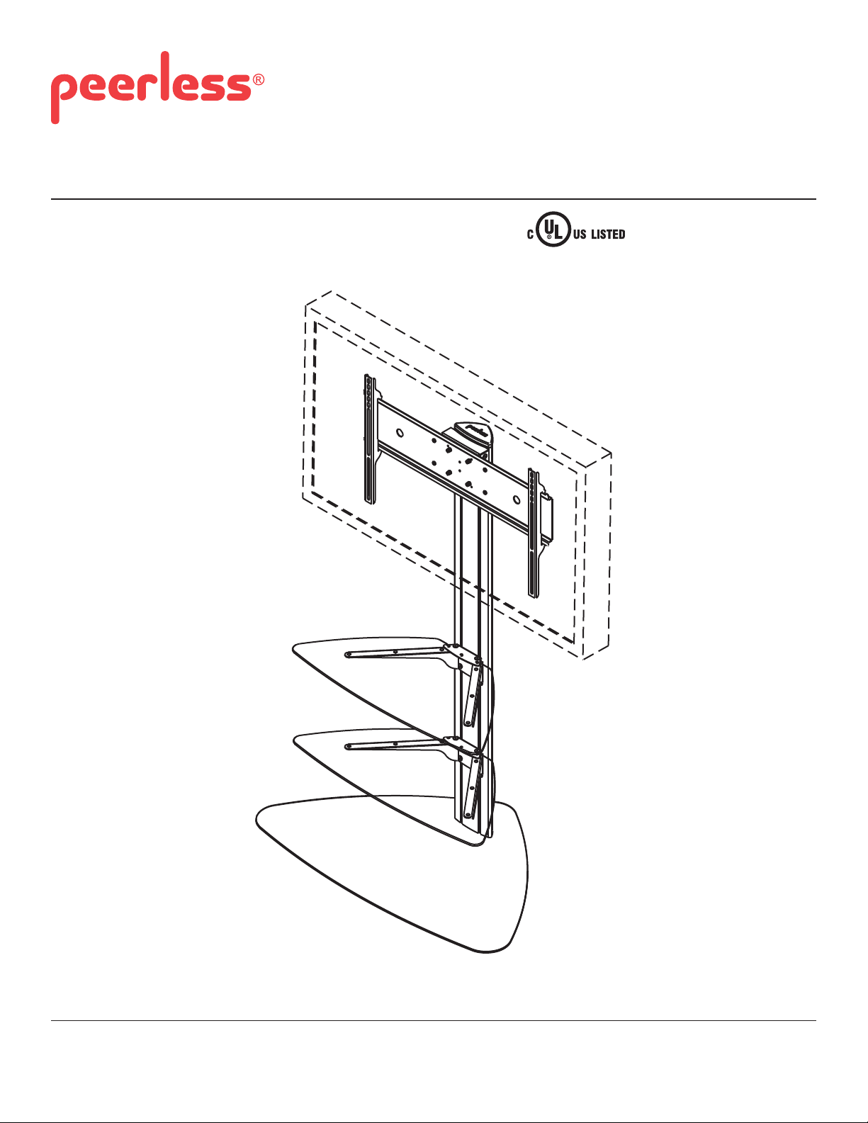
Installation and Assembly:
32" - 65" Flat Panel Display Stand
Models: SS550P, SS550P-S
This product is UL Listed. It must be
installed by a qualifi ed professional
installer.
Max Load Capacity:
150 lb (68 kg) display
50 lb (22.7 kg) per shelf
2300 White Oak Circle • Aurora, Il 60502 • (800) 865-2112 • Fax: (800) 359-6500 • www.peerlessmounts.com
ISSUED: 09-05-06 SHEET #: 202-9166-10 05-23-12
Page 2
NOTE: Read entire instruction sheet before you start installation and assembly.
WARNING
• Do not begin to install your Peerless product until you have read and understood the instructions and warnings
contained in this Installation Sheet. If you have any questions regarding any of the instructions or warnings, please
call Peerless customer care at 1-800-729-0307.
• This product should only be installed by someone of good mechanical aptitude, and fully understands
these instructions.
• Never exceed the Maximum Load Capacity on page 1.
• Always use an assistant or mechanical lifting equipment to safely lift and position equipment.
• Tighten screws fi rmly, but do not overtighten. Overtightening can damage the items, greatly reducing their holding
power.
• The cart is not affi xed or secured to the fl oor, and may therefore tip over and/or fall if display and/or stand is shaken
or hit. Always monitor children and do not let children play alone around stand as they could get hurt by a falling
display. Not recommended for use in areas with heavy traffi c.
Tools Needed for Assembly
• level
• phillips screwdriver
Table of Contents
Parts List............................................................................................................................................................................ 3, 4
Assembling Floor Stand .........................................................................................................................................................4
Attaching Display Using Universal Plate with Adapter Brackets.............................................................................................8
Attaching Display with VESA 100 Mounting Pattern.............................................................................................................11
2 of 11
ISSUED: 09-05-06 SHEET #: 202-9166-10 05-23-12
Page 3
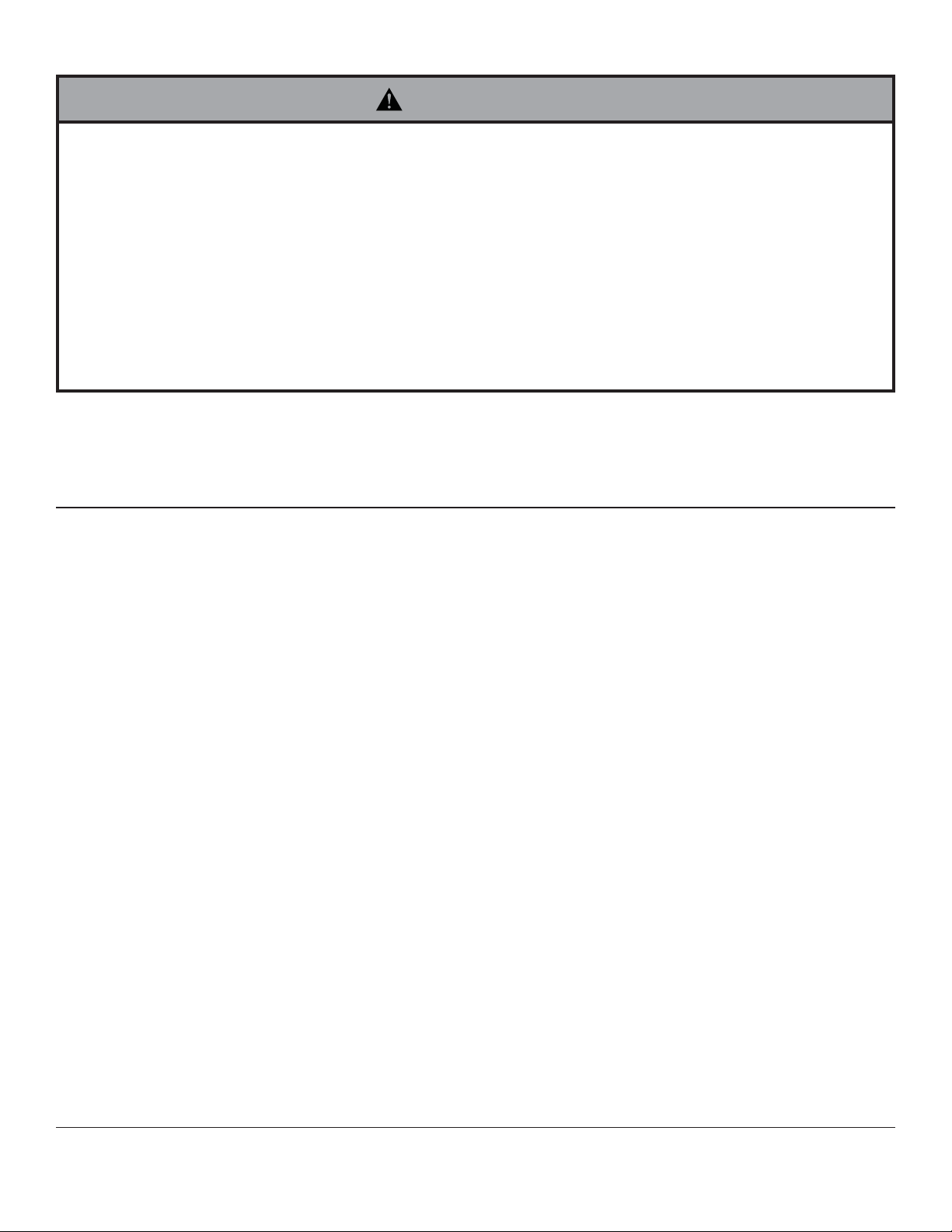
Parts List
SS550P SS550P-S
Description Qty. Part # Part#
A
screen mount bracket 1 201-P1156 201-4156
B hook plate 1 201-P1157 201-4157
C shelf support 2 201-P1158 201-4158
D shelf clamp bracket 2 201-P1159 201-4159
E base 1 201-P1633 201-4633
F universal plate 1 201-P1109 201-4109
G adapter bracket 2 201-P1513 200-4513
H upright 1 580-P1180 580-4180
I glass shelf 2 590-1208 590-1208
J top cover 1 590-1210 590-4210
K button bumper 18 590-1209 590-1209
L 1/4-20 x 12mm decorative screw 18 520-2325 520-1325
M 1/4-20 x 20mm decorative screw 4 520-2326 520-1326
N 1/4-20mm nut 18 530-1050 530-2031
P 3/8-16 x 2.5" socket screw 3 520-9550 520-9550
Q 7/32" allen wrench 1 560-9715 560-9715
R 4mm allen wrench 1 560-9646 560-9646
S adhesive felt 1 570-0043 570-0043
T M10 x15mm socket screw 4 520-9262 520-9262
U 6mm allen wrench 1 560-9716 560-9716
Before you begin, make sure all parts shown are included with your product.
A
C
B
Some parts may appear slightly different than illustrated.
E
I
L
F
Q
3 of 11
M
R
D
J
K
G
N
H
S
UTP
ISSUED: 09-05-06 SHEET #: 202-9166-10 05-23-12
Page 4
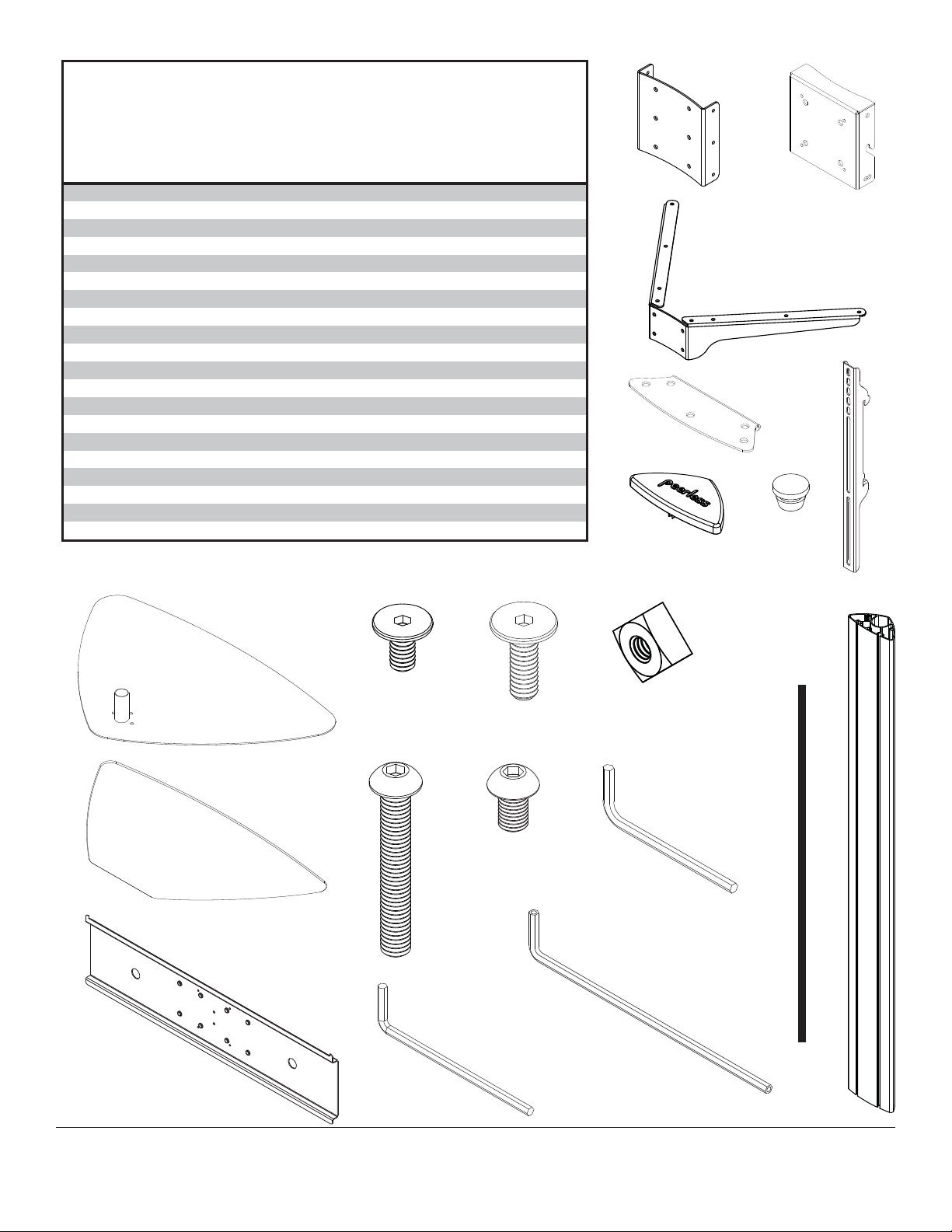
Adapter Bracket Fasteners
M5 x 12 mm (4)
(520-1027)
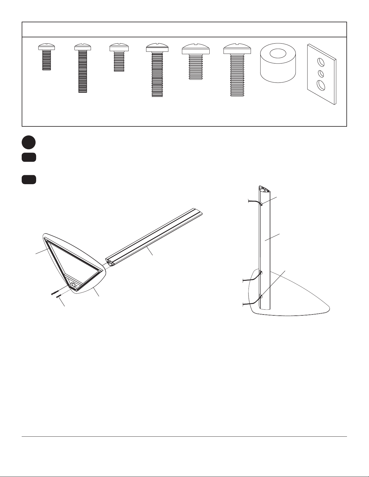
Cut adhesive felt (S) into four pieces as shown in fi gure 1.1 below and affi x to bottom of base (E).
1
1-1
1-2
Attach upright (H) to base (E) using three 3/8-16 x 2.5" socket screws (P). Tighten screws using 7/32" allen
wrench (Q).
Run cords through upright (H) using cord management holes as shown in fi gure 1.2.
M6 x 12 mm (4)
M5 x 25 mm (4)
(520-9543)
(520-1128)
M6 x 25 mm (4)
(520-1208)
M8 x 12 mm (4)
(520-9571)
M8 x 25 mm (4)
(520-1031)
.75" spacer (4)
(540-1059)
Multi-washer (4)
(580-1398)
CORD
MANAGEMENT HOLE
H
S
fi g. 1.1
P
E
H
CORD
MANAGEMENT HOLE
fi g. 1.2
4 of 11
ISSUED: 09-05-06 SHEET #: 202-9166-10 05-23-12
Page 5

Loosely attach four 1/4-20 x 12 mm screws
2
(L) and 1/4-20 nuts (N) to shelf support (C).
N
3
3-1
Slide shelf support (C) onto upright (H) so that
1/4-20 nuts (N) slide into slots of upright (H) as
shown in fi gure 3 and detail 1. Slide shelf support
to desired position, level, then tighten 1/4-20 x 12
mm screws (L) using 4 mm allen wrench (R).
NOTE: Max of two shelves can be used
Max height of top shelf is 34" from base.
Max height of second shelf is 28" from base.
L
C
Insert six button bumpers (K) into shelf support
4 5
(C).
4-1
Place glass shelf (I) on shelf support.
H
DETAIL 1
5-1
C
L
N
SLOT
H
fi g. 3
Insert three button bumpers (K) into bottom of
shelf clamp bracket (D).
Attach shelf clamp bracket (D) to shelf support (C)
using two 1/4-20 x 20 mm screws (M) and two
1/4-20 nuts (N).
I
D
M
K
C
N
K
C
5 of 11
ISSUED: 09-05-06 SHEET #: 202-9166-10 05-23-12
Page 6

Loosely attach six 1/4-20 x 12 mm screws (L) and
6
1/4-20 nuts (N) to display mount bracket (A).
N
Slide display mount bracket (A) onto upright (H)
7
so that 1/4-20 nuts (N) slide into slots of upright
(H) as shown in fi gure 7 and detail 2. Slide display
mount bracket to desired position, level, then
tighten 1/4-20 x 12 mm screws (L) using 4 mm
allen wrench (R).
A
L
Snap top cover (J) onto upright (H).
8
A
N
H
DETAIL 2
Insert two 1/4-20 x 12 mm screws (L) into display
9
mount bracket (A), leaving 1/8" of exposed thread
as shown in fi gure 9 and detail 3.
L
SLOT
H
fi g. 7
J
H
6 of 11
L
A
1/8"
DETAIL 3
fi g. 9
ISSUED: 09-05-06 SHEET #: 202-9166-10 05-23-12
Page 7

Attaching Display Using Universal Plate with Adapter Brackets
For attaching displays with VESA 100 hole pattern, skip to page 11.
10
Attach universal plate (F) to hook plate (B) using
four M10 x 15 mm socket screws (T). Tighten
screws using 6 mm allen wrench (U).
11
Attach hook plate (B) to display mount bracket (A).
B
F
B
A
T
Insert two 1/4-20 x 12 mm screws (L) into holes indicated below for desired display orientation. Tighten all screws
12
using 4 mm allen wrench (R).
L
L
L
2° Backward Tilt 5° Forward TiltNo Tilt
7 of 11
ISSUED: 09-05-06 SHEET #: 202-9166-10 05-23-12
Page 8

Installing Adapter Brackets
WARNING
• Tighten screws so adapter brackets are fi rmly attached. Do not tighten with excessive force. Overtightening can
cause stress damage to screws, greatly reducing their holding power and possibly causing screw heads to become
detached. Tighten to 40 in. • lb (4.5 N.M.) maximum torque.
• If screws don't get three complete turns in the display inserts or if screws bottom out and bracket is still not tightly
secured, damage may occur to display or product may fail.
To prevent scratching the display, set a cloth on a fl at, level surface that will support the weight of the display. Place
13
display face side down. Refer to display manufacturers instructions or customer service, for removing any knobs,
base, cover, or screw(s) on the back of the display to prepare mounting. These need to be removed to allow the
adapter brackets to be attached. Select the small, medium, large or extra large screws from the baffl ed fastener
pack then attach tilt brackets to display following fi gure 13.1 or 13.2.
NOTE: Top and bottom mounting holes must be used for attaching brackets. Verify that all holes are properly
aligned, and then tighten screws using a phillips screwdriver.
X
G
Notes:
• The number of fasteners used will vary,
depending upon the type of display.
• Multi-washers and spacers may not be
used, depending upon the type of display.
• Use the corresponding hole in the multi-
washer that matches your screw size as
shown.
CENTER BRACKETS
VERTICALLY ON
BACK OF DISPLAY
X
Note: "X" dimensions should be equal.
MULTI-WASHER
MEDIUM HOLE FOR M5 SCREWS
SMALL HOLE FOR M4 SCREWS
LARGE HOLE FOR M6 SCREWS
NOTE: For fl at back displays proceed to step 13-1. For bump-out or recessed back display skip to step 13-2.
8 of 11
ISSUED: 09-05-06 SHEET #: 202-9166-10 05-23-12
Page 9

For Flat Back Display
13-1
Begin with the shortest length screw, hand thread through multi-washer and adapter bracket into display as
shown below. Screw must make at least three full turns into the mounting hole and fi t snug into place. Do not
over tighten. If screw cannot make three full turns into the display, select a longer length screw from the baffl ed
fastener pack. Repeat for remaining mounting holes, level brackets and tighten screws.
NOTE: Spacers may not be used, depending upon the type of display.
If you have any questions, please call Peerless customer care at 1-800-865-2112.
fi g. 13.1
DISPLAY
MULTI-WASHER
SCREW
ADAPTER
BRACKET (G)
For Bump-out or Recessed Back Display
13-2
Begin with longer length screw, hand thread through multi-washer, adapter bracket and spacer in that order into
display as shown below. Screw must make at least three full turns into the mounting hole and fi t snug into place.
Do not over tighten. If screw cannot make three full turns into the display, select a longer length screw from the
baffl ed fastener pack. Repeat for remaining mounting holes, level brackets and tighten screws.
DISPLAY
SPACER
If you have any questions, please call Peerless customer care at 1-800-865-2112.
fi g. 13.2
MULTI-WASHER
SCREW
ADAPTER
BRACKET (G)
9 of 11
ISSUED: 09-05-06 SHEET #: 202-9166-10 05-23-12
Page 10

Mounting and Removing Flat Panel Display
WARNING
• Always use an assistant or mechanical lifting equipment to safely lift and position the display.
Hook adapter brackets (G) onto universal plate (F), then slowly swing display in as shown. Turn screws clockwise
14
at least six times to prevent display from being removed as shown in detail 4.
NOTE: Tighten using 4 mm allen wrench (R).
Display can be adjusted horizontally if desired.
NOTE: It is important to lock display down! To lock the display down, tighten screws to adapter bracket as
shown in detail 4.
To remove display from mount, loosen screws, swing display away from mount, and lift display off of mount.
F
SCREWS
G
DETAIL 4
10 of 11
G
ISSUED: 09-05-06 SHEET #: 202-9166-10 05-23-12
Page 11

Attaching Display with VESA 100 Mounting Pattern
WARNING
• If screws don't get three complete turns in the display inserts or if screws bottom out and hook plate is still not tightly
secured, damage may occur to display or product may fail.
10
Choose hole pattern as shown in fi gure 10. Attach
hook plate (B) to back of display using four M4 x
12 mm screws. Tighten screws using a phillips
screwdriver.
fi g 10
M4 X 12 MM SCREWS
B
11
Attach hook plate (B) to display mount bracket (A).
B
A
Insert two 1/4-20 x 12 mm screws (L) into holes indicated below for desired display orientation. Tighten all screws
12
using 4 mm allen wrench (R).
L
L
No Tilt
2° Backward Tilt
5° Forward Tilt
L
11 of 11
All other brand and product names are trademarks or registered trademarks of their respective owners.
ISSUED: 09-05-06 SHEET #: 202-9166-10 05-23-12
© 2012, Peerless Industries, Inc. All rights reserved.
 Loading...