

Page 1
User Guide
XTREME OUTDOOR SOUNDBAR
MODEL: SPK-080
www.peerless-av.com
1
2017-07-25 #:180-9109-2 (2017-08-28)
Page 2
WARNING
ENG - This product is designed to be installed on wood stud, solid concrete or cinder block walls. Before
installing make sure the supporting surface will support the combined load of the equipment and hardware.
Screws must be tightly secured. Do not overtighten screws or damage can occur and product may fail. Never
exceed the Maximum Load Capacity. Always use an assistant or mechanical lifting equipment to safely lift and
position equipment. Be careful not to pinch fi ngers when operating the mount. For support please call customer
care at 1-800-865-2112.
ENG
Symbols
ENG
WARNING
ENG
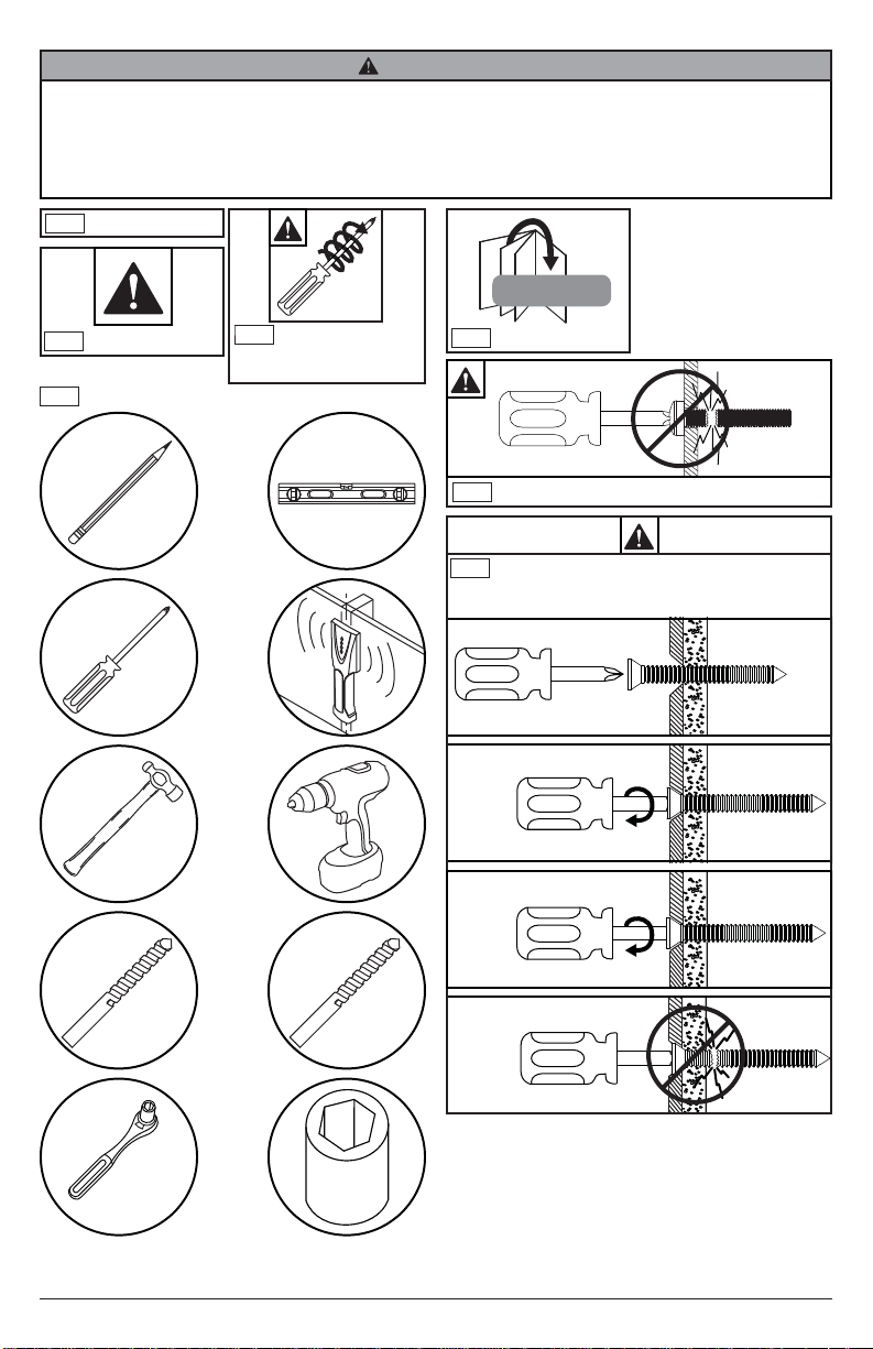
Tools Needed for Assembly.
Screws must get at
ENG
least three full turns
and fi t snug.
x3
#
ENG
Skip to step.
Do not overtighten screws.
ENG
To properly tighten screws: Tighten until screw
ENG
head makes contact, then tighten another 1/2
turn. Do not overtighten screws.
1
2
3
+1/2
5/32"
(4mm)
5/16"
(8mm)
3/8"
(10mm)
4
2
2017-07-25 #:180-9109-2 (2017-08-28)
Page 3
GENERAL SAFETY PRECAUTIONS
WARNING
RISK OF ELECTRICAL SHOCK
To reduce the risk of electric shock, do not disassemble the unit under any circumstances. No user serviceable
parts inside. All product services should be done by the Peerless-AV certifi ed service personnel.
Read before operating equipment
Thank you for purchasing our product. Before using it, please read this user manual carefully and follow the
instructions correctly for safe operation. Please keep this manual handy for future reference. Also, please be sure
to always include this user manual in the packaging when transferring or transporting this product to a different
location.
Batteries Installed Warning
CAUTION - Danger of explosion if batteries are incorrectly replaced. Replace only with the same or equivalent type.
The batteries shall not be exposed to excessive heat such as sunshine, fi re or the like.
NOTE - The soundbar remote control does not carry an IP rating. Do NOT allow the remote control to get wet. Do
NOT leave the remote control outside when the soundbar is not in use.
CAUTION:
These servicing instructions are for use by qualifi ed service personnel only. To reduce the risk of electric shock, do
NOT perform any servicing other than that contained in the operating instructions unless you are qualifi ed to do so.
1. Read these instructions.
2. Keep these instructions.
3. Heed all warnings.
4. Follow all instructions.
5. Do NOT defeat the safety purpose of the polarized or grounding type plug. A polarized plug has two blades
with one wider than the other. A grounding type plug has two blades and a third grounding prong. The wide
blade or the third prong are provided for your safety. If the provided plug does not fi t into your outlet, consult an
electrician for replacement of the obsolete outlet.
6. Protect the power cord from being walked on or pinched particularly at plugs, convenience receptacles, and the
point where they exit from the apparatus.
7. Refer all servicing to qualifi ed service personnel. Servicing is required when the apparatus has been damaged
in any way, such as power-supply cord or plug is damaged, does not operate normally, or has been dropped.
8. Only use attachments/accessories specifi ed by the manufacturer.
9. In case of emergency such as fi re or electric shock caused by the product, immediately contact 911 or proper
emergency police/fi re service agencies in your country.
10. Follow instructions for wall, shelf or ceiling mounting as recommended by the manufacturer.
11. Use properly rated power voltage. Use of non-rated voltage may cause fi re, electric shock and severe damages
to the product.
12. Do NOT open the cabinet under any circumstances. High voltage inside of this product may cause electric
shock.
13. Do NOT, under any circumstances, modify or disassemble this product as it may cause fi re, electric shock, or
severe damages to the product. Also any unauthorized modifi cations made to the product automatically void
product warranty.
14. Never touch antenna lines, wires, if applicable, power cables or power plugs in such circumstances as lightning
and thunder as it may cause electric shock.
15. Any severe physical impact on the product may cause certain components to fall out of place within and break,
which may cause fi re or electric shock. In such event, do not operate the product. Contact the manufacturer for
support.
16. Periodically clean dust off the power plug, to keep it clean and dry, ensuring proper and safe operation of the
product.
17. Do NOT destroy, process, or place the product close to any heating device; do NOT bend or twist power cords,
power plugs, cables, or wires with excessive force; do NOT place any heavy object on the product as all of the
above may cause damages to the product and result in fi re or electric shock.
3
2017-07-25 #:180-9109-2 (2017-08-28)
Page 4

18. Do NOT touch power plugs with wet hands.
19. Always make sure to plug in the power plug fi rmly and completely. Incompletely placed power plugs may cause
fi re or electric shock due to built up heat emission.
20. Do NOT use any non-rated power sockets or power strips with many other devices jointly plugged in. The wire
of non-designated capacity may cause fi re due to built up heat emission. Try to use a single, directly dedicated
and rated GFI power socket for the product for safe operation.
21. In case of product malfunction or unusual events such as electrical burning smell, smoke, or loss of content
signals on soundbar due to internal overheating, immediately turn off and unplug the power and contact the
manufacturer.
22. Do NOT install the product at such unstable locations as moving objects, constantly vibrating props, or uneven
surfaces. Improper installation may cause products to fall off. Follow mounting instructions properly for safe
operation of the product.
23. Do NOT install the product near any poisonous gas or chemically unstable atmosphere as it may cause fi re.
24. Do NOT install the product near any strong magnetic or electrical current fi eld. It may cause fi re, electric shock,
or severe damages to the product. The product may be subject to any electromagnetic radiation, causing
failure.
25. Do NOT leave any fi re source, such as candles, close to or on the product as it may be a cause for fi re or
damages to the product.
26. Do NOT move or transport the product with any cables (power cables, content connectivity cables) plugged
in to the source devices. Damages may occur to the cables, plugs, or jointing connectors of the cables due to
forcible bending and stress, which may cause damages to the waterproof seal of the product, making it subject
to fi re, electric shock, or shorted circuit.
27. When unplugging, always grab the plugs of power cords or cables. Improper pulling of the cords or cables may
cause damages to the waterproof seal of the product, making it subject to fi re, electric shock, or shorted circuit.
28. Do NOT climb on the product.
29. Do NOT use any other power cords or connection cables than what is provided with the product or from the
manufacturer directly. Use of untested, unauthorized, or substituted power cords or connection cables may be
a cause for malfunction, fi re, electric shock, or severe damages to the product. Also such use of improper or
undesignated power cords or connection cables will void product warranty.
30. Always leave the power Off when plugging or unplugging the power cords or connection cables to avoid electric
shock or damages to the product.
31. Do NOT use any chemical such as paint thinner or benzene to clean the product’s exterior. It may cause
scratches on the surface, erasing proper indications, identifi cation labels, or instructions on the exterior, which
may be a cause for misuse and improper operation of the product.
32. Never power wash or spray water at the front grill of the soundbar. While the speaker gaskets are IP65 rated
and won't allow ingress of water to the electrical components, doing so may cause damage to the drivers and
void the warranty.
4
2017-07-25 #:180-9109-2 (2017-08-28)
Page 5

FCC CAUTION
To assure continued compliance and possible undesirable interference, ferrite cores may be used when connecting
this TV to video equipment; maintain at least 400mm (15.75 inches) spacing to other peripheral devices.
FCC STATEMENT
This equipment has been tested and found to comply with the limits for a Class B digital device, pursuant to Part
15 of the FCC Rule. These limits are designed to provide reasonable protection against harmful interference in a
residential installation. This equipment generates, uses and can radiate radio frequency energy and, if not installed
and used in accordance with these instructions, may cause harmful interference to radio communications; however,
there is no guarantee that interference will not occur in a particular installation. If this equipment does cause harmful
interference to radio or television reception, which can be determined by turning the equipment off and on, the user
is encouraged to try to correct the interference by one or more of the following measures:
1. Reorient or relocate the receiving antenna.
2. Increase the separation between the equipment and receiver.
3. Connect the equipment into an outlet on a circuit different from that to which the receiver is connected.
4. Consult the dealer or an experienced radio/TV technician for help.
This device complies with Part 15 of the FCC Rules. Operation is subject to the following two conditions:
• This device may not cause harmful interference.
• This device must accept any interference received, including interference that may cause undesired operation.
Relevant Information
Record your soundbar's model and serial number here for future reference. Keep this user manual in an accessible
location in the event settings need to be changed or service is desired.
Note: Your soundbar's serial number can be found on the box and on the rear input panel.
Model Number ____________________________________
Serial Number ____________________________________
5
2017-07-25 #:180-9109-2 (2017-08-28)
Page 6
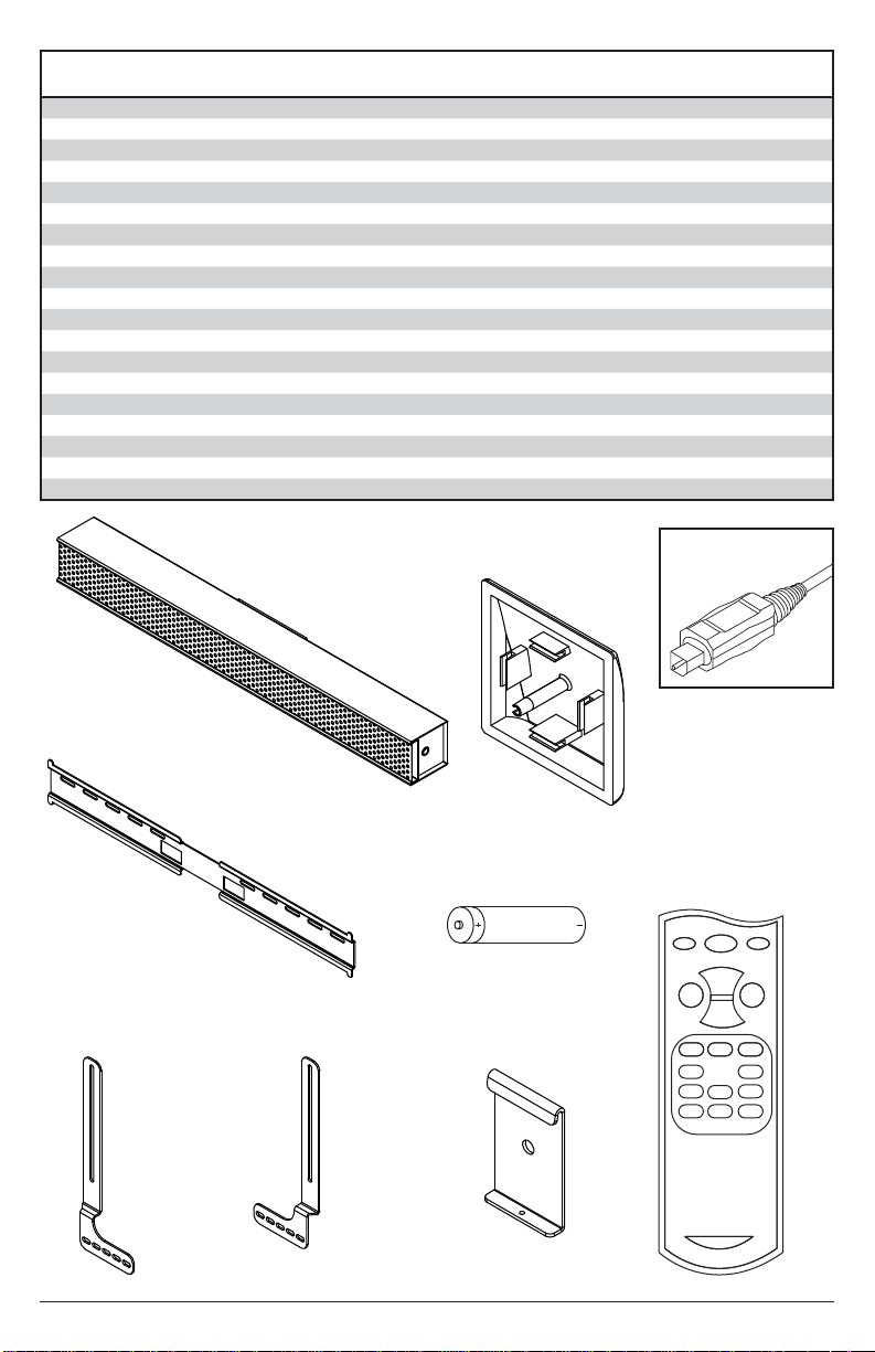
Parts List
A soundbar 1 soundbar
B hook-on bracket 2 180-0265
C wall plate 1 180-0264
D left mount bracket 1 180-0268
E right mount bracket 1 180-0267
F remote control 1 remote
G #14 x 2.5" wood screw 2 520-D1033
H 8mm concrete anchor 2 590-0320
I lock washer 2 540-3622
J nylon washer 2 590-1231
K M8 X 25mm socket pin screw 2 520-D1101
L M8 x 40mm socket pin screw 2 520-D1152
M .5" spacer 2 540-1059
N .25" spacer 2 540-1002
O M5 x 10mm self-tapping 2 520-D1164
P end cap 2 590-0407
Q 4mm security allen wrench 1 520-1129
R AAA batery 2 410-0040
S toslink cable 1 410-0098
Part #Description Qty
C (1)
wall plate
D (1)
left mount bracket
A (1)
soundbar
E (1)
right mount bracket
P (2)
end cap
R (2)
AAA batery
B (2)
hook-on bracket
S (1)
toslink cable
F (1)
remote control
6
2017-07-25 #:180-9109-2 (2017-08-28)
Page 7
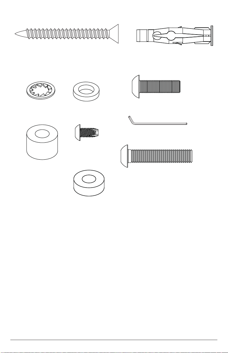
G (2)
#14 x 2-1/2" wood screw
H (2)
8mm concrete anchor
I (2)
lock washer
M (2)
.5" spacer
J (2)
nylon washer
O (2)
M5 x 10mm
N (2)
.25" spacer
K (2)
M8 x 25mm
(1)
Q
4mm allen wrench
L (2)
M8 x 40mm
7
2017-07-25 #:180-9109-2 (2017-08-28)
Page 8
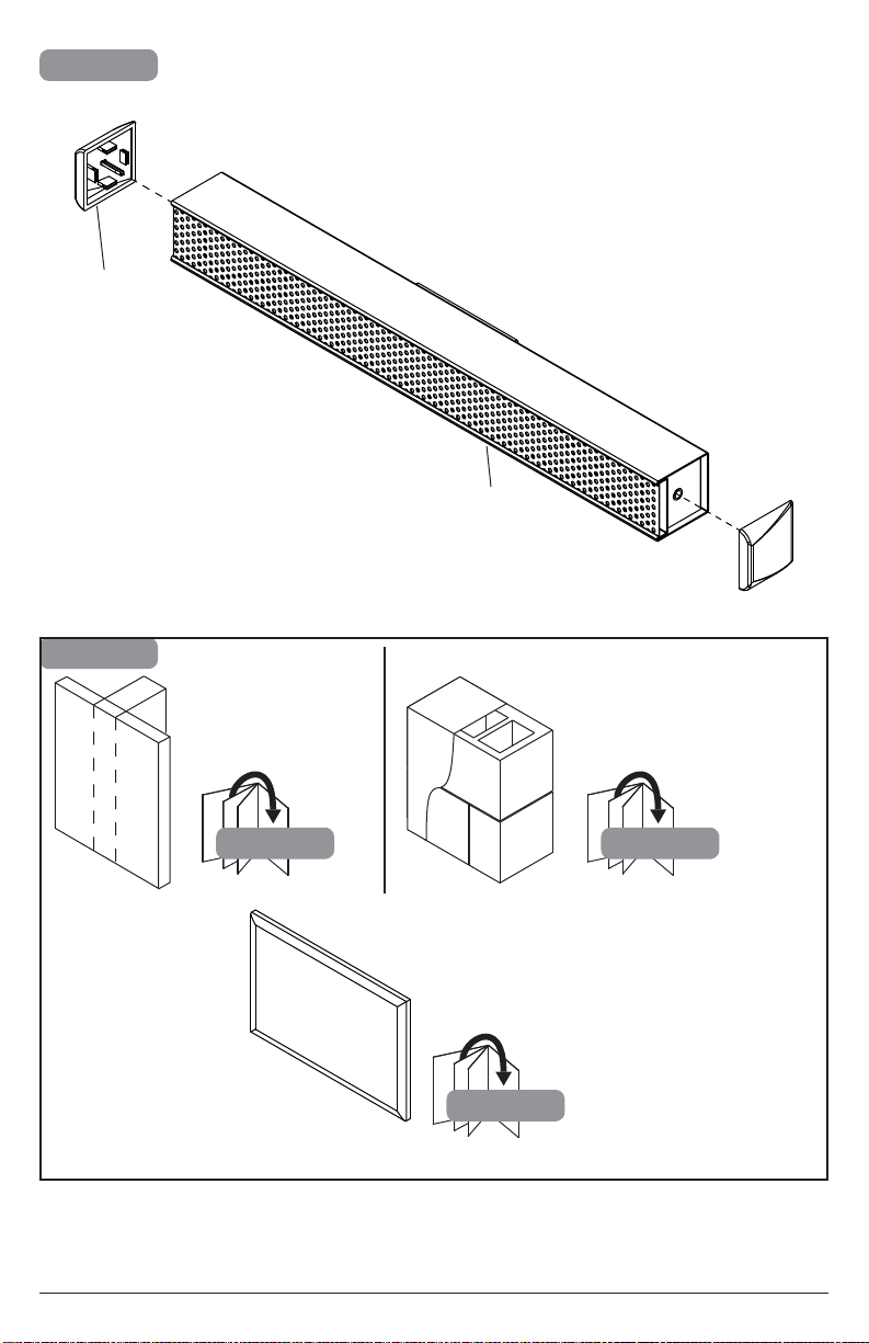
1
P (2)
2
A
Wood stud wall.
2a-1
Display.
8
Concrete/Cinder block.
2b-1
2c-1
2017-07-25 #:180-9109-2 (2017-08-28)
Page 9
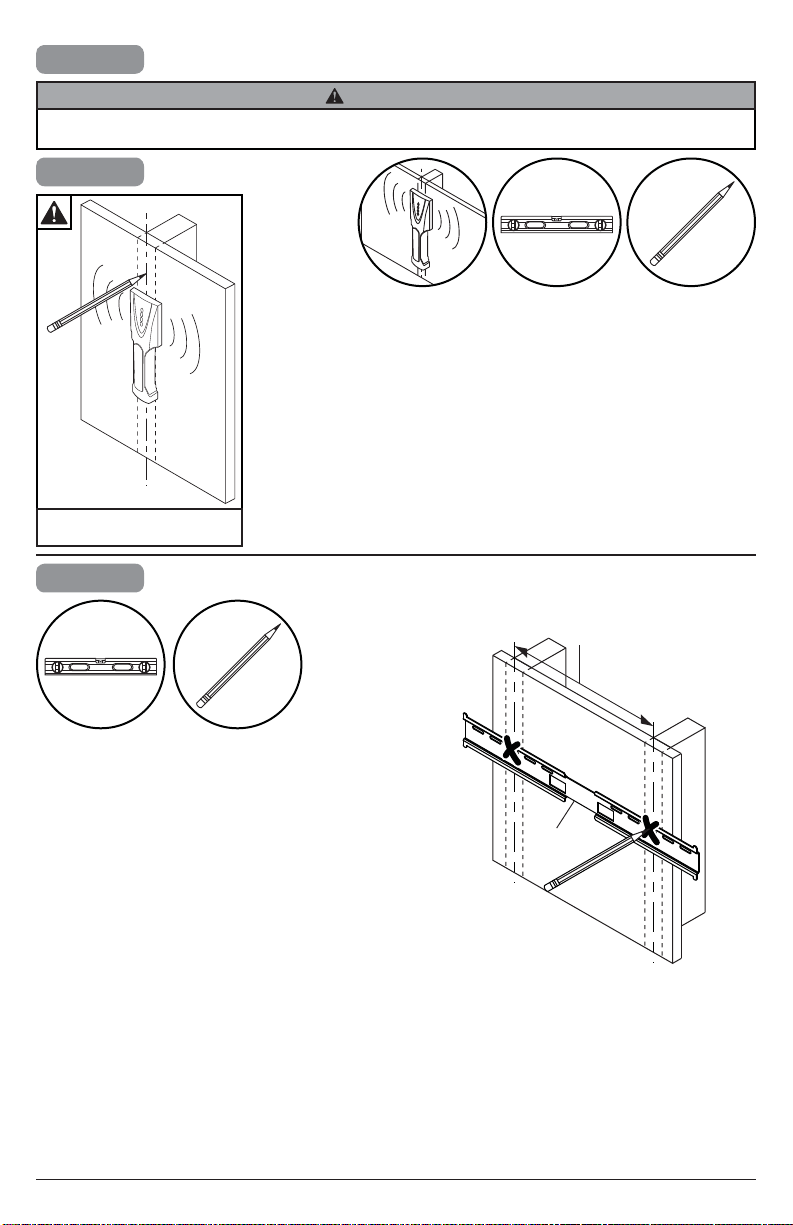
2a
WARNING
ENG - When installing Peerless wall mounts on a wood stud wall covered with gypsum board (drywall), verify that
the wood studs are a minimum of 2" x 4" nominal size. Do not install over gypsum board thicker than 5/8".
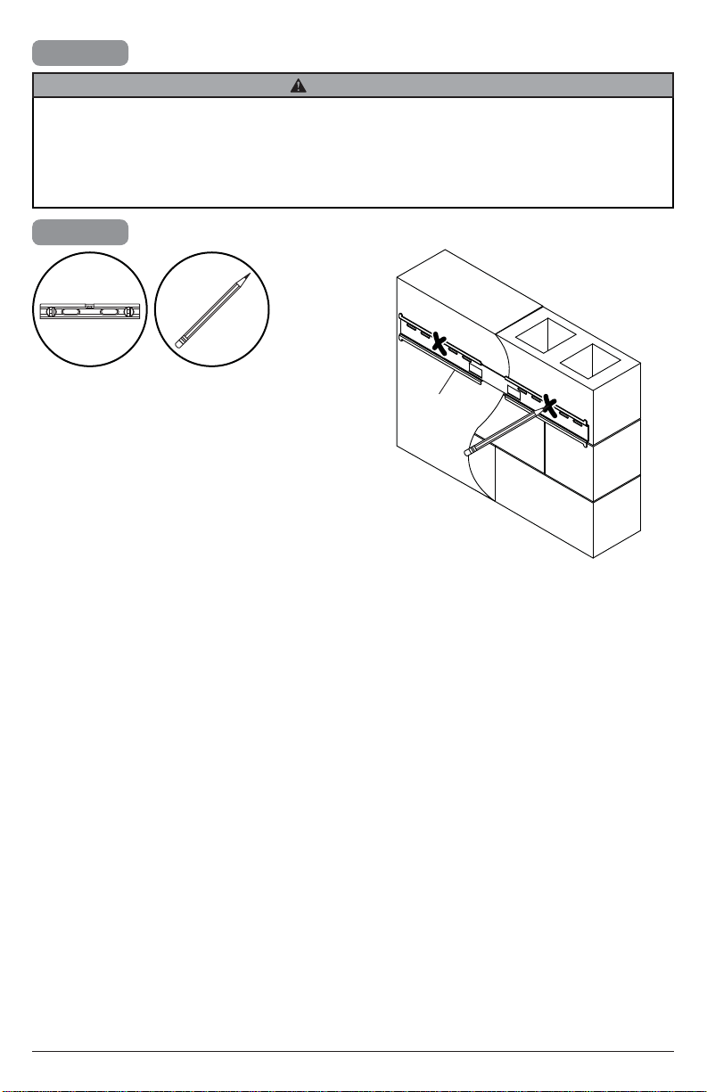
2a-1
Use stud fi nder to locate and
mark stud center lines.
2a-2
16" - 24"
(41cm - 61cm)
Level wallplate. Mark mounting holes on stud
center lines.
C
9
2017-07-25 #:180-9109-2 (2017-08-28)
Page 10
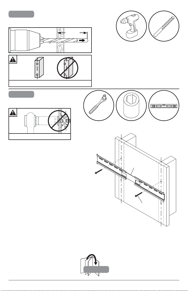
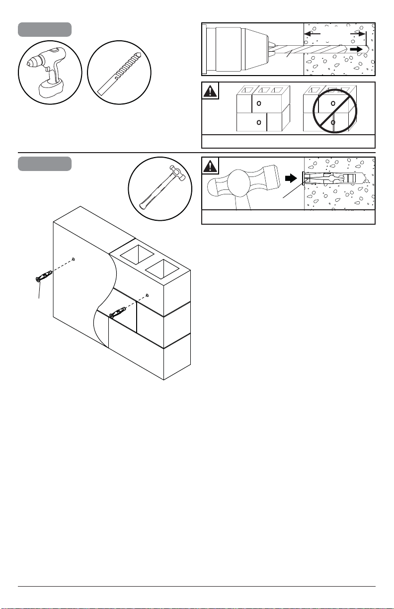
2a-3
Drill mounting holes into supporting surface
(2.5" (64mm) minimum depth required).
(64mm)
5/32"
(4mm)
Mounting hole must center on stud.
2a-4
Level wallplate. Install using wood
screws provided.
Maximum 80 in. • lb (9 N.M.).
2.5"
5/32"
(4mm)
3/8"
(10mm)
10
C
G (4)
2
2017-07-25 #:180-9109-2 (2017-08-28)
Page 11
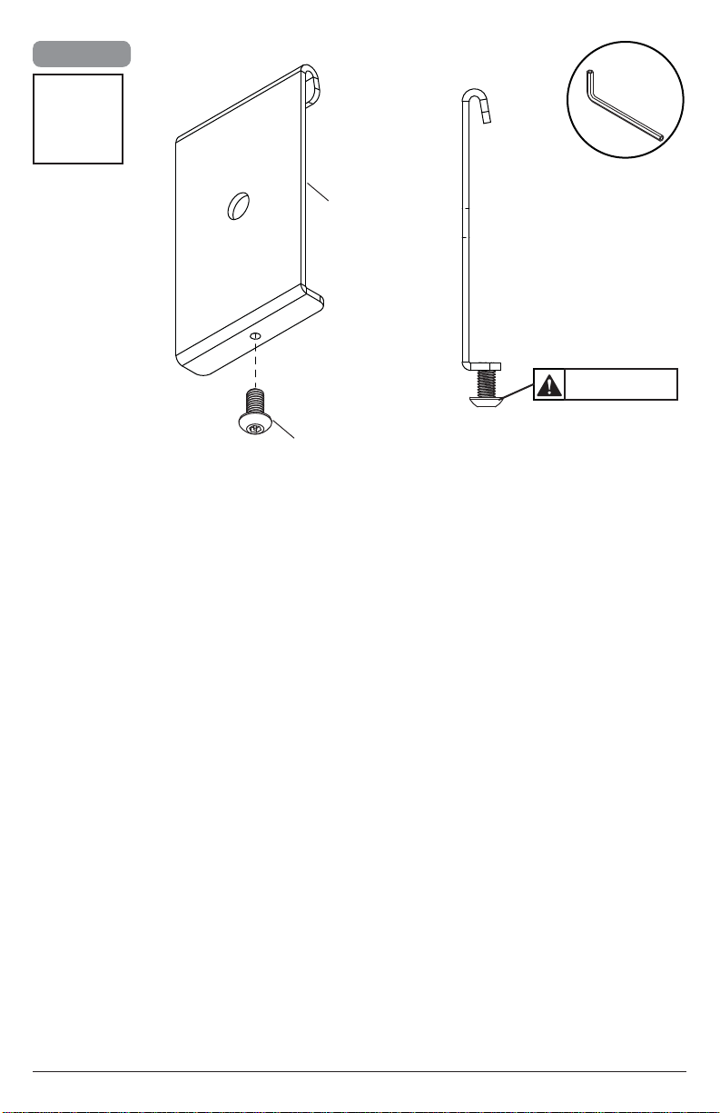
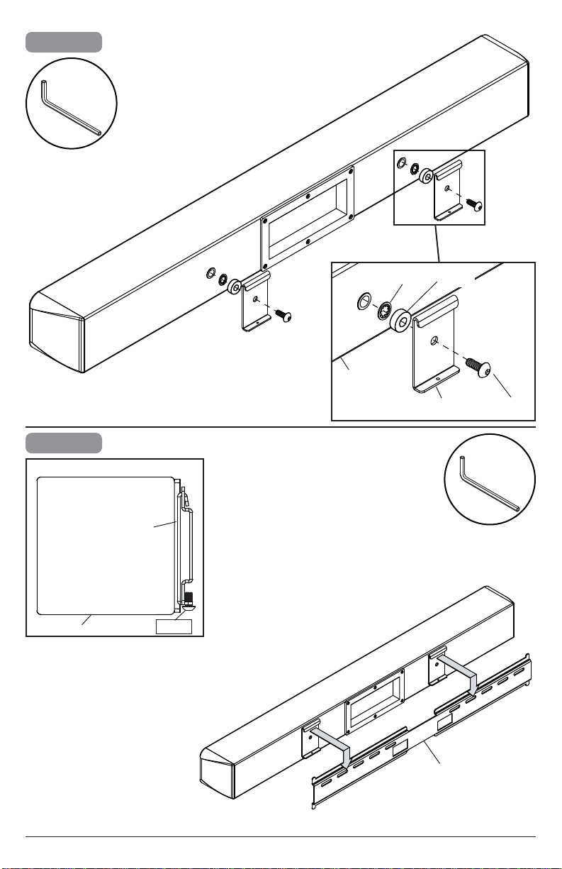
2a-5
x2
Q
B
Do not fully tighten
O
11
2017-07-25 #:180-9109-2 (2017-08-28)
Page 12

2a-6
Q
I (2) N (2)
A
2a-7
A
SIDE VIEW
B (2)
tighten
B (2)
C
K (2)
Q
12
2017-07-25 #:180-9109-2 (2017-08-28)
Page 13
2b
WARNING
ENG - When installing Peerless wall mounts on a concrete wall, the wall must be at least 8" thick with a minimum
compressive strength of 2000 psi. When installing Peerless wall mounts on a cinder block wall, the cinder blocks
must meet ASTM C-90 specifi cations and have a minimum nominal width of 8". Do not drill into mortar joints!
Be sure to mount in a solid part of the block, generally 1" (25 mm) minimum from the side of the block. It is
suggested that a standard electric drill on slow setting is used to drill the hole instead of a hammer drill to avoid
breaking out the back of the hole when entering a void or cavity. Never attach concrete expansion anchors to
concrete or cinder block covered with plaster, drywall or other fi nishing material.
2b-1
Level wallplate. Mark mounting holes.
C
13
2017-07-25 #:180-9109-2 (2017-08-28)
Page 14
2b-2
2.5"
(64mm)
5/16"
(8mm)
Drill mounting holes into supporting surface
(2.5" (64mm) minimum depth required).
2b-3
H (2)
5/16"
(8mm)
Do not drill into mortar joints.
H
Insert anchor fl ush to concrete.
14
2017-07-25 #:180-9109-2 (2017-08-28)
Page 15
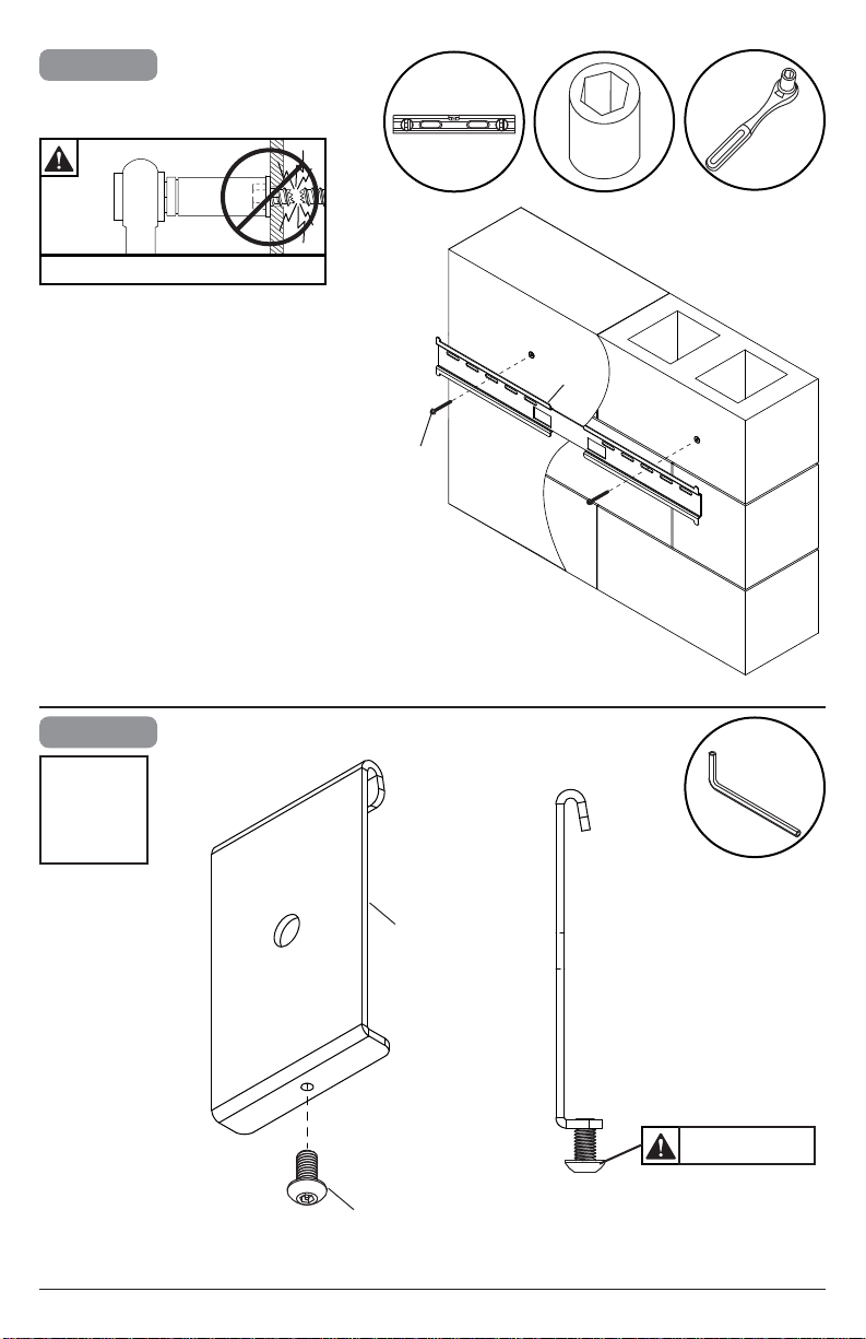
2b-4
Level wallplate. Install using concrete
anchors and wood screws provided.
Maximum 80 in. • lb (9 N.M.).
3/8"
(10mm)
C
G (4)
2b-5
x2
O
B
15
Q
Do not fully tighten
2017-07-25 #:180-9109-2 (2017-08-28)
Page 16
2b-6
Q
I (2) N (2)
A
2b-7
A
SIDE VIEW
B (2)
tighten
B (2)
C
K (2)
Q
16
2017-07-25 #:180-9109-2 (2017-08-28)
Page 17
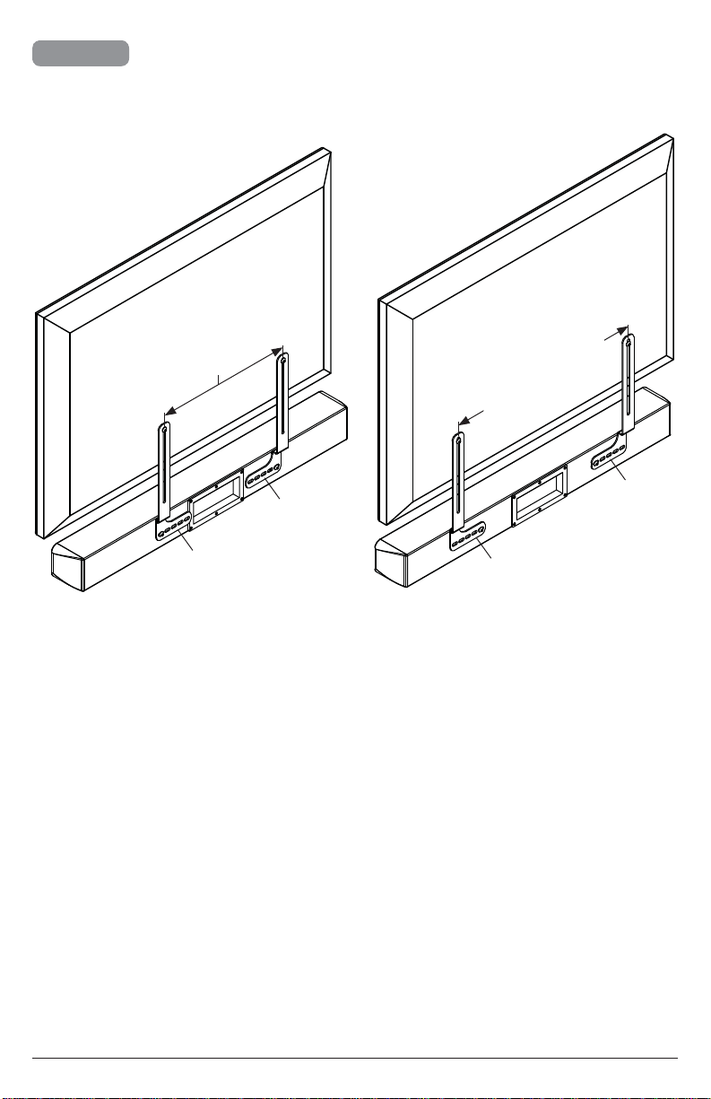
2c-1
Position display screen-side down on a fl at, clean surface.
Position soundbar grill-side down either above or below
display. Determine which bracket confi guration below fi ts
your display
7.9" - 15.7"
(200mm - 400mm)
D
15.7" - 23.6"
(400mm - 600mm)
D
E
17
E
2017-07-25 #:180-9109-2 (2017-08-28)
Page 18
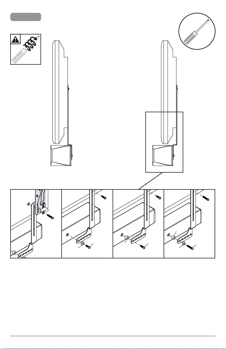
2c-2
Determine which hardware to use based on the depth
needed.
x3
J
M
N
KL
M
*Hardware included for installing soundbar only. To
attach display, use hardware included with display
mount.
18
2017-07-25 #:180-9109-2 (2017-08-28)
N
L
Page 19
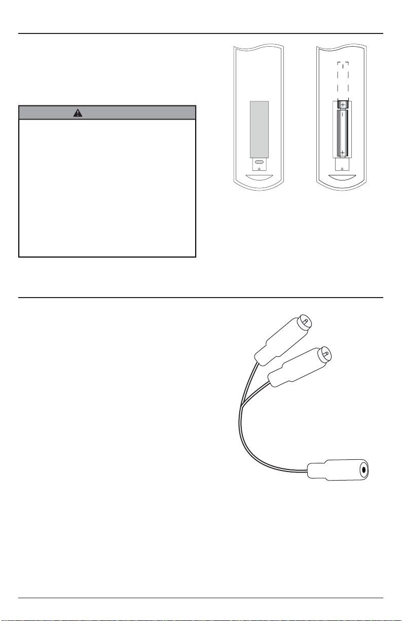
Battery Installation and Replacement
The remote control is powered by two 15V AAA batteries.
To install or replace batteries:
1. Install/Replace the batteries by removing the battery
cover and sliding in two new "AAA" batteries.
Important: Match the batteries to the (+)
and (-) marks on the inside of the remote control.
2. Snap the battery cover back onto the remote control.
CAUTION
Incorrect usage of batteries can result in leaks or
bursting. Peerless-AV recommends the following
battery use:
1. Do NOT mix battery brands.
2. Do NOT combine new and old batteries. This can
shorten the battery life or cause liquid leakage of
the batteries.
3. Remove dead batteries immediately to prevent
battery acid from leaking into the battery
compartment.
4. Do NOT touch exposed battery acid as it may
injure skin.
5. Remove the batteries if you do not intend to use
the remote control for a long period of time.
Cable Management and Soundbar Orientation
For Digital Connection:
1. Connect the provided toslink cable to the optical
digital audio out port on the TV. Make sure the cable
is fully inserted.
2. Plug the other end of the optical cable into the
optical port on the soundbar. Make sure that there
are no excessive bends or pinch points when
connecting the optical cable.
3. Plug the soundbar's power cable into the nearest
outlet.
4. Note: When optical digital audio port is not being
used on the soundbar the port cover should remain
closed
For Analog Connection:
1. Connect the soundbar’s 3.5mm audio cable to the
audio out port on the TV. Make sure the 3.5mm
audio cable is fully inserted.
2. Plug the soundbar's power cable into the nearest
outlet.
3. Note: If the audio output of the TV is RCA stereo, a
female 3.5mm to male RCA stereo audio cable will
be required.
Female 3.5mm to male RCA stereo
audio cable (sold seperately)
19
2017-07-25 #:180-9109-2 (2017-08-28)
Page 20
OPERATING INSTRUCTIONS
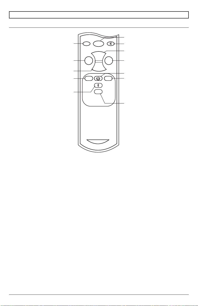
Using The Remote Control
Discrete OFF
Bass-
Volume-
Treble -
OFF
ON
Vol+
Vol-
Discrete ON
Mute Toggle
Volume +
Bass+Bass-
Treble +Treble -
Bass+
Power Toggle
Treble +
Bluetooth
peerless-AV
1. Turn on the TV.
2. Turn on the soundbar by aiming the included remote
at the front of the soundbar and pressing the ON
button. Your soundbar will begin to play the audio
coming from your display. If you don’t hear any
audio coming from the soundbar aim the remote at
the soundbar and press the AUX button. You should
see a green light illuminated when the Aux input is
selected. When AUX is selected on the soundbar
it will support both the analog 3.5mm input and the
optical digital audio input.
3. To listen to a Bluetooth® enabled device, aim the
included remote at the front of the soundbar and
press the button with the Bluetooth icon on it.
4. When the soundbar is switched to the Bluetooth
input a blue light will appear on the soundbar. Make
sure that Bluetooth function is enabled on the
device that is being connected and that the device
is within Bluetooth range (33’). Scan for devices on
your Bluetooth enabled device and select “PeerlessAV” from the list of devices. Start playing content
from your Bluetooth enabled device.
AUX
AUX Input
Remote control functions
Discrete Off – Powers the soundbar Off
Discrete On – Powers the soundbar On
Mute – Toggles the mute on and off
Bass - – Decreases the bass level
Bass + – Increases the bass level
Volume + – Increases the output level
Volume - – Decreases the output level
Treble - – Decreases the treble level
Treble + – Increases the treble level
Power – Toggles power on and off
Bluetooth – switches to bluetooth input
AUX – switches to 3.5mm/optical input
NOTE - The soundbar remote control does not carry
an IP rating. Do NOT allow the remote control to get
wet. Do NOT leave the remote control outside when the
soundbar is not in use.
20
2017-07-25 #:180-9109-2 (2017-08-28)
Page 21
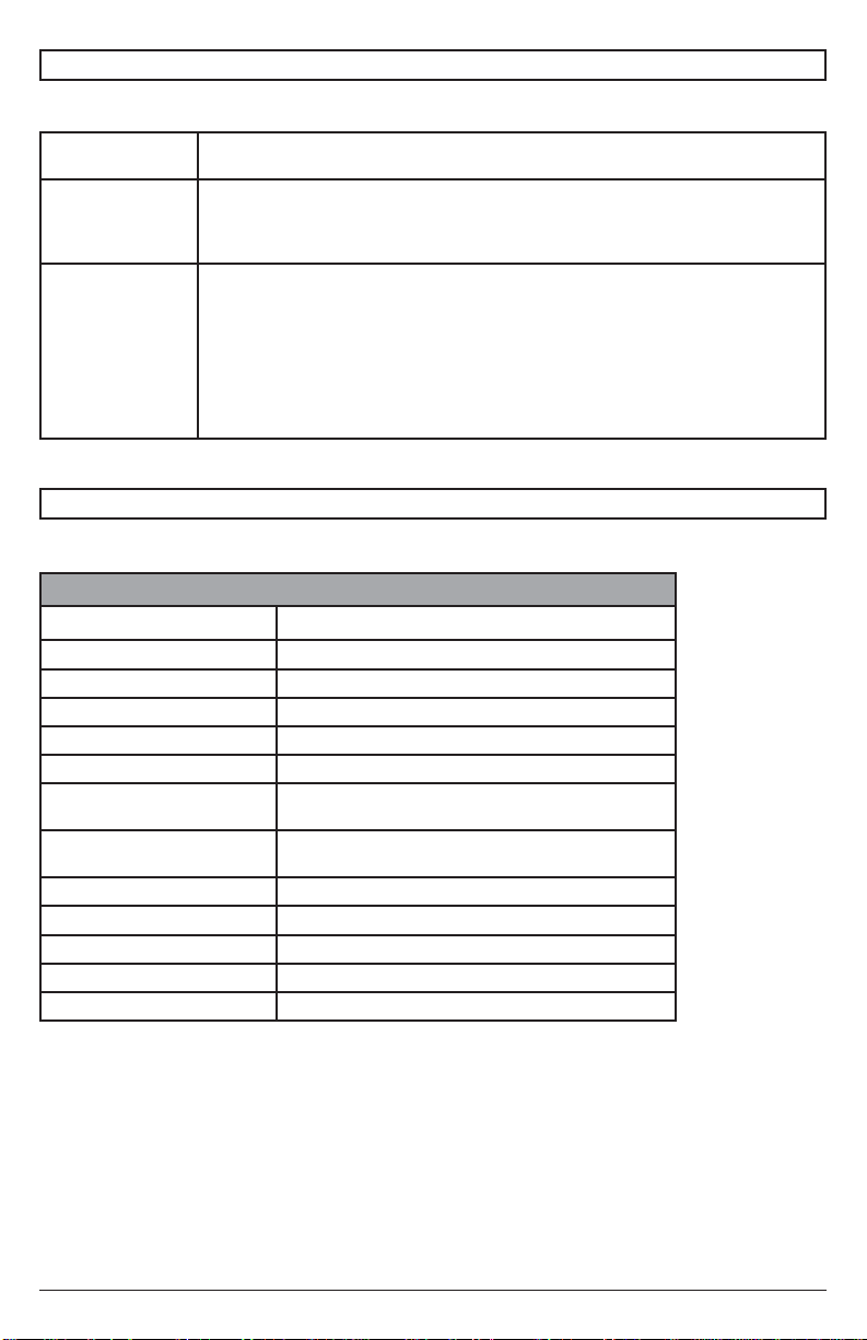
Troubleshooting
TIPS
Distorted Audio • Source level should not exceed 80%.
No Audio • Verify that the soundbar is plugged into an outlet that has power. Ensure that the audio
Problem
Connecting a
Bluetooth Enabled
Device
• Verify the the 3.5mm audio plug is fully inserted.
signal cable is connected to the audio-out port on the TV. Make sure that the source
volume is not muted and that the volume level is not at zero. Aim the remote at the
soundbar and select the desired input of the source that is playing.
• Aim the remote at the front of the soundbar and hit the Blutetooth icon.
• Make sure Bluetooth is enabled on the device that is being connected and that you are
within 33' of the soundbar.
• Complete a device scan on the device that is being connected and select "peerlessAV" from the list of devices.
• If "peerless-AV" is not present on the list, turn the Bluetooth on the device off. Turn the
Bluetooth on the soundbar off by switching to the Aux input. Turn the Bluetooth on the
soundbar back on by pressing the Bluetooth button on the soundbar remote. Turn the
Bluetooth on your device back on and perform another scan.
PRODUCT SPECIFICATIONS
Specifi cations subject to change without notice
Sound Bar
TV Size Range 42" (107cm) and above
Built-in Class D Amplifi er Total System Power: 200 watts
SPL 105db
Crossover Digital Signal Processing (DSP)
Drivers (2) 3" [76mm] Aluminum Drivers
Tweeters (2) 1.5" [38mm] Titanium Domes
Audio Inputs (1) Digital Optical Audio, (1) Analog 3.5mm connector,
Environmental Protection
Frequency Response 50Hz - 20kHz
Operating Temperature Range -40° - 120°F (-40°C - 49°C)
Vesa Mounting Pattern 400mm wide pattern
Product Dimensions 38.13" x 3.91" x 4.32" (969 x 99 x 110mm)
Product Weight 9.7lb (4.4kg)
(1) Bluetooth 4.0 input
IP65
Rating
21
2017-07-25 #:180-9109-2 (2017-08-28)
Page 22

The Peerless-AV Xtreme Outdoor Soundbar is warrantied to be free of defects in material and workmanship from the time of
ONE YEAR PARTS & LABOR LIMITED WARRANTY
purchase by the original owner. If this product is found and proved to be defective under the terms and conditions of this warranty,
Peerless-AV will repair or replace defective parts with new and/or reconditioned parts at no charge for the parts and labor to the
original owner, subject to the terms and conditions of this Limited Warranty.
This Limited Warranty covers failures due to defects in material or workmanship that occur during normal residential or commercial
use as follows:
1. Parts – the warranty period for parts are: one (1) year from the date of original purchase. During the applicable Limited
Warranty period for parts, defective parts will be replaced at no charge. Parts used for the replacement will be warrantied for the
remainder of the original warranty period for those parts.
2. Labor – the warranty period for labor is: one (1) year from the date of original purchase. During the applicable Limited Warranty
period for labor, Peerless-AV will provide the labor for warranty repair at no charge for a period of one (1) year from the date of
original purchase.
3. Original owner must provide verifi cation of the date of purchase when requesting Limited Warranty Services. A copy of the
original Dated Sales Receipt is required together with the product to obtain service under this Limited Warranty. Product
Registration at the time of purchase is required.
4. All repairs must be performed by a Peerless-AV Authorized Service Provider.
5. Customer is responsible for returning (including any freight and shipping costs) defective unit to a Peerless-AV Authorized
Service Provider. If the product is found to have no defects, the customer will be responsible for return shipping costs as well.
THIS LIMITED WARRANTY DOES NOT COVER:
• Shipping damage.
• Damage caused during customer unpacking, and/or removal of packing materials.
• Damage due to improper, incorrect or insuffi cient AC voltage.
• Damage due to power surges or lightning strikes.
• Damage which results from fi re, fl ood, lightning, tornado, hurricane, large hail, extremely gusty winds, sand storms, vandalism,
terrorism or other acts of nature.
• Any unit which has been modifi ed or damaged due to improper installation or failure to obey the operating instructions provided
in the User Manual.
• Any failure, loss, damage or personal injury due to accident, neglect, misuse, abuse, improper operation, improper maintenance,
improper storage, alteration to the unit, or failure by the consumer to follow operating instructions provided in the User Manual.
• Any owner other than the original owner.
• Any unit purchased from an unauthorized seller.
• Indirect, consequential, or special damages, except as required by federal or state laws.
• Any unit tampered with, modifi ed, adjusted or repaired by any party other than the Peerless-AV Authorized Service Provider.
• Any cosmetic damages to the surface or exterior that has been defaced or faded, or caused by normal wear and tear or exposure to chemicals, acid rain, large hail or adverse weather conditions.
• Because the soundbar cabinet and components are hand-assembled and altered, we do not cover minor cabinet blemishes or
minor scratches to the exterior of the unit.
• Any damage, scratches or blemishes to the soundbar and/or exterior cabinet due to end-user cleaning.
• If the original product serial number has been removed, defaced or tampered with in any way.
• Return shipping when no defect is found.
Peerless-AV and its representatives or agents shall in no event be liable for any general, indirect or consequential damages arising
out of/or caused by the use of/or the inability to use this product.
This warranty is made in lieu of all other warranties, expressed or implied, and all other liabilities on the part of Peerless-AV. Any
other warranties, including the warranties of merchantability and fi tness for a particular purpose are hereby disclaimed by Peerless-
AV and its representatives and/or agents.
The laws of some states do not allow exclusion of implied warranties; therefore, this warranty shall be deemed modifi ed to be
consistent with such laws. This Limited Warranty gives you specifi c legal rights. You may also have other rights that vary from state
to state.
All warranty inspections and repairs must be performed by Peerless-AV or its authorized service representations.
Customer Care: 800.865.2112 or 630.375.5100
22
2017-07-25 #:180-9109-2 (2017-08-28)
Page 23

Guía del Usuario
XTREME BARRA DE SONIDO PARA EXTERIORES
MODELO: SPK-080
www.peerless-av.com
23
2017-07-25 #:180-9109-2 (2017-08-28)
Page 24

ADVERTENCIA
ESP - Este producto está diseñado para ser instalado en paredes con montantes de madera, en paredes de
concreto macizo o en paredes de hormigón de escorias. Antes de instalarlo, asegúrese de que la superfi cie de
apoyo sostendrá la carga combinada del equipo y los fi jadores. Los tornillos se tienen que fi jar fi rmemente. No
apriete los tornillos en exceso, ya que se pueden dañar y el producto podría fallar. Nunca exceda la Capacidad
Máxima de Carga. Siempre cuente con la ayuda de un asistente o utilice un equipo mecánico de izar para
levantar y colocar el equipo con más seguridad Tenga cuidado de no pincharse los dedos cuando mueva el
soporte. Si necesita ayuda, por favor, llame a Servicio al Cliente de Peerless al 1-800-865-2112.
ESP
Símbolos
ESP
ESP
ADVERTENCIA
ESP
Herramientas necesarias para el ensamblaje.
Continúe con el
paso.
#
x3
Los tornillos tienen
ESP
que dar, por lo
menos, tres vueltas
completas y quedar
ajustados.
No apriete de más los tornillos.
ESP
Apriete adecuado de los tornillos: Apriete hasta
ESP
que la cabeza del tornillo haga contacto y luego
apriete otra 1/2 vuelta. No apriete de más los
tornillos.
1
2
5/32"
(4mm)
5/16"
(8mm)
3/8"
(10mm)
24
3
+1/2
4
2017-07-25 #:180-9109-2 (2017-08-28)
Page 25

PRECAUCIONES DE SEGURIDAD GENERAL
ADVERTENCIA
RIESGO DE CHOQUE ELÉCTRICO
Para reducir el riesgo de choque eléctrico, no desarme la unidad bajo ninguna circunstancia. No tiene piezas
que puedan ser reparadas por el usuario. Todos los servicios de los productos deben ser proporcionados por
personal de servicio certifi cado de Peerless-AV.
Lea antes de utilizar el producto
Gracias por comprar nuestro producto. Antes de utilizarlo, lea este manual del usuario atentamente y siga las
instrucciones correctamente para utilizarlo con seguridad. Mantenga este manual a mano para su referencia.
Además, asegúrese siempre de incluir este manual del usuario en el embalaje cuando traslade o transporte este
producto a otro lugar.
Advertencia de pilas instaladas
PRECAUCIÓN - Existe peligro de derrame si las pilas se remplazan incorrectamente. Remplácelas solo con el
mismo modelo o uno equivalente. Las pilas no se deben exponer a calor excesivo, como la luz del sol, el fuego o
elementos similares.
NOTA: El control remoto de la barra de sonido no cuenta con una clasifi cación de protección de entrada. NO
permita que se moje el control remoto. NO deje el control remoto afuera cuando no esté utilizando la barra de
sonido.
Precaución:
Para reducir el riesgo de descarga eléctrica, no realice ningún tipo de reparación que no esté incluida en estas
instrucciones, a menos que esté capacitado para hacerlo.
1. Lea estas instrucciones.
2. Guarde estas instrucciones.
3. Preste atención a todas las advertencias.
4. Siga todas las instrucciones.
5. No haga mal uso del enchufe polarizado o con descarga a tierra, de manera que no sea seguro. Un enchufe
polarizado tiene dos clavijas, una de las cuales es más ancha que la otra. Un enchufe con descarga a tierra,
tiene dos clavijas y una tercera punta con descarga a tierra. La clavija ancha y la tercera punta se proporcionan
para su seguridad. Si el enchufe proporcionado no cabe en el receptáculo, consulte a un electricista para
remplazar el receptáculo obsoleto.
6. Proteja el cable eléctrico de manera que no lo pisen ni lo pinchen, particularmente en los enchufes, los
receptáculos para los aparatos y los sitios por los que salen los cables de los aparatos.
7. Deje todas las reparaciones en manos del personal de servicio capacitado. Las reparaciones son necesarias
cuando el aparato ha sufrido algún daño (el cable de corriente eléctrica o el enchufe se ha dañado), no
funciona bien o se ha caído.
8. Use solamente los fi jadores o accesorios especifi cados por el fabricante.
9. En caso de una emergencia, como un incendio o choque eléctrico causado por el producto, llame, de
inmediato, al 9-1-1 o al número apropiado de las agencias de servicios de emergencia de la policía o los
bomberos de su país.
10. Siga las instrucciones para la instalación en paredes, repisas o techos, según las recomendaciones del
fabricante.
11. Use voltaje con la potencia nominal adecuada. Usar un voltaje que no tenga la potencia nominal adecuada
puede causar un incendio, choque eléctrico y daños graves al producto.
12. No abra los paneles exteriores bajo ninguna circunstancia. El alto voltaje dentro de este producto puede causar
choque eléctrico.
13. NO modifi que ni desarme este producto bajo ninguna circunstancia, ya que puede causar un incendio, choque
eléctrico o daños graves al producto. Además, toda modifi cación no autorizada hecha al producto anulará la
garantía automáticamente.
14. Nunca toque los cordones, los alambres y, si corresponde, los cables eléctricos o los enchufes de las antenas
cuando ocurran rayos o truenos, ya que pueden causar choque eléctrico.
15. Darle golpes fuertes al equipo puede causar que algunos componentes internos se salgan de su lugar y se
rompan, lo cual puede causar choque eléctrico. En ese caso, no utilice el producto. Comuníquese con el
fabricante si necesita ayuda.
16. Quítele el polvo al enchufe periódicamente para mantenerlo limpio y seco y asegurarse de que el producto
funcione bien y con seguridad.
25
2017-07-25 #:180-9109-2 (2017-08-28)
Page 26

17. NO destruya, procese ni coloque el producto cerca de un dispositivo de calefacción; NO doble ni tuerza los
cables eléctricos, los enchufes, los cordones o los alambres con fuerza excesiva; NO coloque objetos pesados
sobre el producto, ya que todo lo anterior puede causar daños al producto y tener como resultado un incendio
o choque eléctrico.
18. NO toque los enchufes con las manos mojadas.
19. Asegúrese siempre de conectar el enchufe fi rme y completamente. No conectar los enchufes completamente
puede causar un incendio o choque eléctrico debido a la acumulación de emisiones de calor.
20. NO use receptáculos ni extensiones múltiples que no tengan la potencia nominal o en los que tenga
conectados muchos dispositivos a la vez. Los cordones de capacidad desconocida pueden causar un incendio
debido a la acumulación de emisiones de calor. Trate de utilizar un enchufe separado e individual, con potencia
nominal y con un interruptor con falla a tierra para que pueda utilizar el producto con seguridad.
21. Si el equipo falla o se da algún suceso inusual, como olor a quemado eléctrico, humo o pérdida de señales de
contenido de la barra de sonido debido al sobrecalentamiento interno, apáguela y desenchúfela de inmediato y
comuníquese con el fabricante.
22. NO instale el producto en superfi cies inestables, como objetos móviles, accesorios que vibren constantemente
o superfi cies desniveladas. La instalación inadecuada puede causar que los productos se caigan. Siga las
instrucciones de instalación correctamente para que pueda utilizar el producto con seguridad.
23. NO instale el producto cerca de gases venenosos ni de atmósferas con inestabilidad química, ya que puede
causar un incendio.
24. NO instale el producto cerca de campos magnéticos o corrientes eléctricas fuertes. Puede causar un incendio,
choque eléctrico o daños graves al producto. Este producto puede estar sujeto a radiación electromagnética, lo
cual puede causar fallas.
25. NO deje ninguna fuente de fuego, como velas, cerca o encima del producto, ya que puede causar un incendio
o daños al producto.
26. NO mueva ni transporte el producto con los cables (cables eléctricos, cables de conectividad de contenido)
conectados a los dispositivos fuente. Doblar o tensar los cables, enchufes o conectores de juntas forzosamente
puede dañarlos, lo cual puede causar daños al sellado impermeable del producto, lo cual puede causar un
incendio, choque eléctrico o corto circuito.
27. Siempre, agarre los cordones o cables eléctricos por los enchufes al desconectarlos. Tirar de los cordones
o cables eléctricos incorrectamente puede causar daños al sellado impermeable del producto, lo cual puede
causar un incendio, choque eléctrico o corto circuito.
28. NO se trepe en el producto.
29. NO utilice cables eléctricos o de conexión que no sean los proporcionados con el producto o por el fabricante
directamente. Sustituir los cables eléctricos o de conexión por cables que no hayan sido probados o
autorizados puede causar fallas, un incendio, choque eléctrico o daños graves al producto. Además, usar los
cables eléctricos o de conexión incorrectos o inadecuados anulará la garantía del producto.
30. Siempre, tenga el producto apagado al conectar o desconectar los cables eléctricos o de conexión para evitar
un choque eléctrico o daños al producto.
31. NO utilice ningún químico, como solvente de pintura o benceno para limpiar el exterior del producto. Podría
rayar las superfi cies, borrar indicaciones necesarias, etiquetas de identifi cación o instrucciones exteriores, lo
cual puede causar el mal uso o funcionamiento del producto.
32. Nunca utilice agua a presión ni de atomizadores frente a la rejilla de la barra de sonido. Aunque las juntas de
los altavoces tienen una clasifi cación de IP65 y no permiten la entrada del agua en los componentes eléctricos,
hacerlo puede dañar los conductores y anular la garantía.
26
2017-07-25 #:180-9109-2 (2017-08-28)
Page 27

PRECAUCIÓN DE LA FCC
Para garantizar el cumplimiento continuo y prevenir la interferencia indeseada, se pueden utilizar núcleos de ferrita
al conectar este TV equipos de video; mantenga una separación de, al menos, 400 mm (15.75 pulgadas) de otros
periféricos.
DECLARACIÓN DE LA FCC
Este equipo ha sido probado y cumple los límites de los dispositivos digitales Clase B, conforme al artículo 15
de las normas de la FCC. Estos límites están diseñados para proporcionar una protección razonable contra
interferencias perjudiciales en instalaciones residenciales. Este equipo genera, utiliza y puede irradiar energía
de radiofrecuencia y, si no se instala y utiliza de acuerdo con estas instrucciones, puede causar interferencias
perjudiciales a las radiocomunicaciones. Sin embargo, no hay garantía de que no se produzcan interferencias en
una instalación en particular. Si este equipo, en efecto, causa interferencias perjudiciales en la recepción de radio
o televisión, lo cual se puede determinar apagando y encendiendo el equipo, se recomienda que el usuario intente
corregir las interferencias mediante una o más de las siguientes medidas:
1. Cambie la orientación o la ubicación de la antena receptora.
2. Aumente la distancia entre el equipo y el receptor.
3. Conecte el equipo a un enchufe que esté en un circuito diferente al que está conectado el receptor.
4. Consulte al distribuidor o a un técnico experto en radios o televisores para obtener ayuda.
Este dispositivo cumple con el artículo 15 de las normas de la FCC. El uso depende de las dos condiciones
siguientes:
• Este dispositivo no puede causar interferencias perjudiciales.
• Este dispositivo tiene que aceptar cualquier interferencia recibida, incluida la que pueda causar el
funcionamiento no deseado.
Información pertinente
Anote el número de modelo y el número de serie de la barra de sonido aquí para su referencia. Guarde este manual
del usuario en un lugar accesible en caso de que necesite cambiar los ajustes o necesite alguna reparación.
Nota: El número de serie de la barra de sonido se encuentra en la caja y en la parte trasera del tablero de entradas.
Número de modelo ____________________________________
Número de serie ______________________________________
27
2017-07-25 #:180-9109-2 (2017-08-28)
Page 28

Parts List
A soundbar 1 soundbar
B hook-on bracket 2 180-0265
C wall plate 1 180-0264
D left mount bracket 1 180-0268
E right mount bracket 1 180-0267
F remote control 1 remote
G #14 x 2.5" wood screw 2 520-D1033
H 8mm concrete anchor 2 590-0320
I lock washer 2 540-3622
J nylon washer 2 590-1231
K M8 X 25mm socket pin screw 2 520-D1101
L M8 x 40mm socket pin screw 2 520-D1152
M .5" spacer 2 540-1059
N .25" spacer 2 540-1002
O M5 x 10mm self-tapping 2 520-D1164
P end cap 2 590-0407
Q 4mm security allen wrench 1 520-1129
R AAA batery 2 410-0040
S toslink cable 1 410-0098
Part #Description Qty
C (1)
wall plate
D (1)
left mount bracket
A (1)
soundbar
E (1)
right mount bracket
P (2)
end cap
R (2)
AAA batery
B (2)
hook-on bracket
S (1)
toslink cable
F (1)
remote control
28
2017-07-25 #:180-9109-2 (2017-08-28)
Page 29

G (2)
#14 x 2-1/2" wood screw
H (2)
8mm concrete anchor
I (2)
lock washer
M (2)
.5" spacer
J (2)
nylon washer
O (2)
M5 x 10mm
N (2)
.25" spacer
K (2)
M8 x 25mm
(1)
Q
4mm allen wrench
L (2)
M8 x 40mm
29
2017-07-25 #:180-9109-2 (2017-08-28)
Page 30

1
P (2)
2
A
Pared de madera
2a-1
Pantalla
30
Concreto/Bloques de hormigón.
2b-1
2c-1
2017-07-25 #:180-9109-2 (2017-08-28)
Page 31

2a
ADVERTENCIA
ESP - Cuando vaya a instalar soportes de pared de Peerless en paredes con montantes de madera recubiertas
con yeso-cartón (gypsum board) verifi que que los montantes tengan un tamaño mínimo de 2" x 4". No instale en
yeso-cartón (gypsum board) de más de 5/8" de grosor.
2a-1
Marque las líneas centrales
del montante.
2a-2
16" - 24"
(41cm - 61cm)
Marque los orifi cios de montaje en las líneas
centrales del montante.
31
C
2017-07-25 #:180-9109-2 (2017-08-28)
Page 32

2a-3
Taladre los agujeros de montaje en la superfi cie de
apoyo; se requiere una profundidad mínima de 2.5"
(64mm).
2.5"
(64mm)
5/32"
(4mm)
El orifi cio debe quedar centrado en el montante.
2a-4
Nivele e instale.
Máxima 80 in. • lb (9 N.M.).
5/32"
(4mm)
3/8"
(10mm)
32
C
G (4)
2017-07-25 #:180-9109-2 (2017-08-28)
Page 33

2a-5
x2
Q
B
No apriete.
O
33
2017-07-25 #:180-9109-2 (2017-08-28)
Page 34

2a-6
Q
I (2) N (2)
A
2a-7
VISTA LATERAL
A
B (2)
apriete
B (2)
C
K (2)
Q
34
2017-07-25 #:180-9109-2 (2017-08-28)
Page 35

2b
ADVERTENCIA
ESP - Cuando vaya a instalar soportes de pared de Peerless en paredes de concreto, las paredes tienen que
tener, por lo menos, 8" de grosor con una resistencia a la compresión de 2000 psi como mínimo. Cuando vaya a
instalar soportes de pared de Peerless en paredes de hormigón de escorias, los bloques tienen que cumplir las
especifi caciones de ASTM C-90 y tener un ancho mínimo de 8". ¡No taladre en juntas de argamasa! Asegúrese
de hacer la instalación en la parte sólida del bloque, por lo general, a un mínimo de 1" (25 mm) del extremo del
bloque. Se sugiere utilizar un taladro eléctrico convencional a baja velocidad para hacer los agujeros en vez de
un taladro percutor para no perforar el fondo de los agujeros al entrar en un vacío o una cavidad. Nunca fi je los
anclajes de expansión para concreto a superfi cies de concreto o de bloques de hormigón de escorias recubiertas
con yeso, yeso-cartón u otro material de acabado.
2b-1
Marque los orifi cios de montaje.
C
35
2017-07-25 #:180-9109-2 (2017-08-28)
Page 36

2b-2
2.5"
(64mm)
5/16"
(8mm)
Taladre los agujeros de montaje en la superfi cie
de apoyo; se requiere una profundidad mínima de
2.5" (64mm).
2b-3
H (2)
5/16"
(8mm)
No perfore en las juntas de mortero.
H
Inserte el anclaje a ras con el concreto.
36
2017-07-25 #:180-9109-2 (2017-08-28)
Page 37

2b-4
Nivele e instale.
Máxima 80 in. • lb (9 N.M.).
3/8"
(10mm)
C
G (4)
2b-5
x2
O
B
37
Q
No apriete.
2017-07-25 #:180-9109-2 (2017-08-28)
Page 38

2b-6
Q
I (2) N (2)
A
2b-7
VISTA LATERAL
A
B (2)
apriete
B (2)
C
K (2)
Q
38
2017-07-25 #:180-9109-2 (2017-08-28)
Page 39

2c-1
Coloque el televisor con la pantalla hacia abajo sobre
una superfi cie plana y limpia. Coloque la barra de sonido
con la rejilla hacia abajo, ya sea encima o debajo de la
pantalla. Determine cuál de las siguientes confi guraciones
de los soportes es apta para su pantalla.
7.9" - 15.7"
(200mm - 400mm)
D
15.7" - 23.6"
(400mm - 600mm)
D
E
39
E
2017-07-25 #:180-9109-2 (2017-08-28)
Page 40

2c-2
Determine cuál de los accesorios debe usar de acuerdo
con la profundidad necesaria.
x3
J
M
N
KL
M
*Se incluyen los accesorios para la instalación de la
barra de sonido solamente. Para fi jar la pantalla, use los
accesorios incluidos con el soporte para pantallas.
40
2017-07-25 #:180-9109-2 (2017-08-28)
N
L
Page 41

Instalación y remplazo de las pilas
Remplace las pilas quitando la cubierta de las pilas
y colocando dos pilas AAA nuevas. Para instalar o
remplazar las pilas:
1. Remplace las pilas quitando la cubierta de las pilas y
colocando dos pilas AAA nuevas.
Importante: Coloque las pilas de manera que
los símbolos (+) y (-) coincidan con los que se
encuentran dentro del control remoto.
2. Coloque la cubierta de las pilas en el control remoto.
PRECAUCIÓN
El uso incorrecto de las pilas puede causar fugas o
derrames. Peerless-AV recomienda usar las pilas
como sigue:
1. No combine marcas de pilas.
2. No combine pilas nuevas y viejas. Las pilas
podrían agotarse o derramarse más pronto.
3. Cambie las pilas agotadas de inmediato para
evitar fugas de ácido en el compartimiento de
las pilas.
4. No toque el ácido derramado, ya que puede
causarle daño a la piel.
5. Quite las pilas si no va a utilizar el control
durante un periodo largo.
Manejo de cables y orientación de la barra de sonido
Para conexión digital:
1. Conecte el cable toslink proporcionado al puerto de
la salida óptica de audio digital del TV. Asegúrese
de que el cable entre completamente.
2. Conecte el otro extremo del cable óptico al puerto
óptico de la barra de sonido. Asegúrese de que el
cable óptico no tenga dobleces ni puntos de agarre
excesivos cuando lo conecte.
3. Conecte el cable eléctrico de la barra de sonido en
el enchufe más cercano.
4. Nota: Cuando el puerto de audio digital óptico no se
está utilizando en la barra de sonido, la cubierta de
puerto debe permanecer cerrada
Para conexión análoga:
1. Conecte el cable de audio de 3.5 mm al puerto
de la salida de audio del TV. Asegúrese de que el
cable de audio de 3.5 mm entre completamente.
2. Conecte el cable eléctrico de la barra de sonido en
el enchufe más cercano.
3. Nota: Si la salida de audio del TV es RCA estéreo,
necesitará un cable hembra de audio de 3.5 mm
para un conector macho RCA estéreo.
Cable hembra de audio de 3.5
mm para conector macho RCA
estéreo (se vende por separado)
41
2017-07-25 #:180-9109-2 (2017-08-28)
Page 42

Usar el Control Remoto
Apagado discreto
Volumen-
Agudos -
INSTRUCCIONES DE USO
Encendido discreto
Bajos-
OFF
ON
Vol+
Bass+Bass-
Vol-
Treble +Treble -
Mudo
Volumen +
Bajos+
Encender
Agudos +
Bluetooth
peerless-AV
1. Encienda el TV.
2. Encienda la barra de sonido apuntando el control
remoto incluido hacia el frente de la barra de sonido
y presionando el botón ON. El sonido de la pantalla
comenzará a oírse por la barra de sonido. Si no
oye ningún sonido por la barra de sonido, apunte
el control remoto a la barra de sonido y presione
el botón AUX. Debe ver una luz verde encendida
cuando se seleccione la entrada de Aux. Cuando se
seleccione AUX en la barra de sonido, funcionará
tanto la entrada análoga de 3.5 mm como la
entrada óptica de audio digital.
3. Para oír un dispositivo con Bluetooth® habilitado,
apunte el control remoto incluido hacia el frente de
la barra de sonido y presione el botón que tiene el
ícono de Bluetooth.
4. Se encenderá una luz azul en la barra de sonido
cuando se active la entrada de Bluetooth.
Asegúrese de que la función de Bluetooth esté
activada en el dispositivo que vaya a conectar y que
el dispositivo esté dentro del alcance del Bluetooth
(33’). Detecte los dispositivos en su dispositivo con
Bluetooth habilitado y seleccione "Peerless-AV" de
la lista de dispositivos. Inicie la reproducción de
sonido de su dispositivo con Bluetooth habilitado.
AUX
AUX
Funciones del control remoto
Apagado discreto – Apaga la barra de sonido
Encendido discreto – Enciende la barra de sonido
Mudo – Activa y desactiva el sonido
Bajos - – Disminuye el nivel de los bajos
Bajos + – Incrementa el nivel de los bajos
Volumen + – Incrementa el nivel del volumen.
Volumen - – Disminuye el nivel del volumen.
Agudos - – Disminuye el nivel de los agudos
Agudos + – Incrementa el nivel de los agudos
Encender – Enciende y apaga la barra de sonido
Bluetooth – Cambia a la entrada de Bluetooth
AUX – Cambia a la entrada de 3.5 mm
NOTA: El control remoto de la barra de sonido no
cuenta con una clasifi cación de protección de entrada.
NO permita que se moje el control remoto. NO deje el
control remoto afuera cuando no esté utilizando la barra
de sonido.
42
2017-07-25 #:180-9109-2 (2017-08-28)
Page 43

Solución de Problemas
CONSEJOS
Distorsión del
No hay audio • Verifi que que la barra de sonido esté conectada en el receptáculo y que tenga
Problema para
conectar con
un dispositivo
con Bluetooth
habilitado
• El nivel de la fuente no debe exceder el 80%.
audio
• Verifi que que el cable de audio de 3.5 mm haya entrado completamente.
electricidad. Asegúrese de que el cabe para la señal de audio esté conectado al puerto
de la salida de audio del TV.Asegúrese de que el volumen de la fuente no esté en
mudo y que el nivel del volumen no esté en cero. Apunte el control remoto hacia la
barra de sonido y seleccione la entrada correspondiente a la fuente de sonido.
• Apunte el control remoto hacia el frente de la barra de sonido y presione el ícono de
Bluetooth.
• Asegúrese de que la función de Bluetooth esté activada en el dispositivo que vaya a
conectar y que el dispositivo esté dentro del alcance de 33’ de la barra de sonido.
• Complete el proceso de detección de dispositivos en el dispositivo que vaya a
conectar y seleccione "peerless-AV" de la lista de dispositivos.
• Si "peerless-AV" no está en la lista, apague el Bluetooth en el dispositivo. Apague el
Bluetooth en la barra de sonido cambiando a la entrada de Aux. Encienda el Bluetooth
en la barra de sonido nuevamente presionando el botón Bluetooth en el control
remoto. Vuelva a encender el Bluetooth en su dispositivo y repita la detección.
ESPECIFICACIONES DEL PRODUCTO
Especifi caciones sujetas a cambio sin aviso.
Barra de Sonido
Gama de tamaños de los TV 42" (107 cm) y más
Amplifi cador integrado Clase D Potencia total del sistema: 200 vatios
SPL 105db
Separador de frecuencias Procesamiento de señales digitales (DSP)
Conductores (2) conductores de aluminio de 3" [76 mm]
Altavoces para agudos (2) domos de titanio de 1.5" [38 mm]
Entradas de audio (1) Audio óptico digital, (1) conector análogo de 3.5 mm,
Clasifi cación de protección
ambiental
Respuesta en frecuencia 50Hz - 20kHz
Gama de temperaturas de
funcionamiento
Confi guración de montaje de
Dimensiones del producto 38.13" x 3.91" x 4.32" (969 x 99 x 110mm)
Peso del producto 9.7lb (4.4kg)
(1) entrada de Bluetooth de 4.0
IP65
-40° - 120°F (-40°C - 49°C)
Confi guración ancha de 400 mm
Vesa
43
2017-07-25 #:180-9109-2 (2017-08-28)
Page 44

GARANTÍA LIMITADA DE UN AÑO EN PIEZAS Y MANO DE
OBRA
Peerless-AV garantiza que el producto Xtreme Outdoor Soundbar estará libre de defectos de los materiales o la manufactura
en la fecha en la que lo compre el dueño original. Si se determina y se demuestra que este producto tiene defectos de acuerdo
con los términos y condiciones de esta garantía, Peerless-AV reparará o remplazará las piezas defectuosas por piezas nuevas o
reacondicionadas sin cargo alguno para el dueño original por las piezas o la mano de obra, conforme a los términos y condiciones
de esta garantía limitada.
Esta garantía limitada cubre fallas debidas a defectos de los materiales o la manufactura que ocurran durante el uso residencial o
comercial normal, como sigue:
1. Piezas – El periodo de garantía de las piezas es: un (1) año desde la fecha de compra original. Durante el periodo correspondiente de la garantía limitada de las piezas, las piezas defectuosas se remplazarán sin costo. Las piezas utilizadas
como remplazo estarán cubiertas durante el resto del periodo de la garantía original de las piezas.
2. Mano de obra – El periodo de garantía de la mano de obra es: un (1) año desde la fecha de compra original. Durante el
periodo correspondiente de la garantía limitada de la mano de obra, Peerless-AV proporcionará la mano de obra para las
reparaciones de acuerdo con la garantía sin costo durante un periodo de un (1) año desde la fecha de compra original.
3. El dueño original tiene que proporcionar verifi cación de la fecha de compra al solicitar los servicios de la garantía limitada.
Se tiene que presentar copia del recibo de compra original que indique la fecha junto con el producto para recibir servicios
de acuerdo con esta garantía limitada. Se requiere que registre el producto en el momento de la compra.
4. Todas las reparaciones tienen que ser realizadas por personal de servicio certifi cado de Peerless-AV.
5. El consumidor es responsable de enviar el producto defectuoso a un proveedor de servicios autorizado de Peerless-AV
(incluidos los costos de fl ete y envío). Si se determina que el producto no tiene defectos, el consumidor será, además,
responsable de pagar los costos del envío de devolución.
ESTA GARANTÍA LIMITADA NO CUBRE:
• Daños causados durante el envío.
• Daños causados mientras el consumidor desempaca o retira los materiales de embalaje.
• Daños causados porque el voltaje de corriente alterna sea inadecuado, incorrecto o insufi ciente.
• Daños causados por las subidas de voltaje o los rayos.
• Daños causados por incendios, inundaciones, tornados, huracanes, granizo grande, vientos extremadamente fuertes, tormen-
tas de arena, vandalismo, terrorismo u otros actos de la naturaleza.
• Las unidades que hayan sido modifi cadas o hayan sufrido daños debido a una instalación incorrecta o a que no se sigan las
instrucciones de uso del manual del usuario.
• Las fallas, las pérdidas, los daños o las lesiones personales debidas a accidentes, negligencia, mal uso, abuso, uso inadec-
uado, mantenimiento inadecuado, almacenamiento inadecuado, cambios hechos a la unidad o que el consumidor no siga las
instrucciones de uso del manual del usuario.
• Los dueños que no sean el dueño original.
• Las unidades compradas a vendedores no autorizados.
• Los daños y perjuicios indirectos, incidentales o especiales, excepto en la medida en la que lo exijan las leyes federales o
estatales.
• Las unidades que hayan sido cambiadas, modifi cadas, ajustadas o reparadas por cualquier otra persona que no sea un prov-
eedor de servicios autorizado de Peerless-AV.
• Daños cosméticos de superfi cies o paneles exteriores que se hayan afeado o desteñido o causados por el uso normal o la
exposición a químicos, lluvia ácida, granizo grande, condiciones climatológicas adversas.
• Debido a que los paneles exteriores y los componentes interiores de la barra de sonido son hechos y modifi cados a mano, no
cubrimos las imperfecciones o rayones menores en el exterior de la unidad.
• Daños, rayones o imperfecciones de la barra de sonido o del exterior de la barra de sonido debido a que el usuario los limpie.
• Si el número de serie del producto original ha sido borrado, mutilado o cambiado de cualquier manera.
• Los costos del envío de devolución si se determina que el producto no tiene defectos.
Peerless-AV y sus representantes o agentes no tendrán responsabilidad en ningún caso de daños y perjuicios generales, indirectos
o incidentales que surjan como resultado de o sean causados por utilizar o no poder utilizar este producto.
Esta garantía remplaza toda otra garantía, expresa o implícita, y todas las demás responsabilidades de Peerless-AV. Por este
medio, Peerless-AV y sus representantes o agentes renuncian a toda otra garantía, incluidas las garantías de comerciabilidad o de
idoneidad para un propósito en particular.
Las leyes de algunos Estados no permiten la exclusión de las garantías implícitas; por lo tanto, se considerará que esta garantía ha
sido modifi cada para conformarse a dichas leyes. Esta garantía limitada le concede derechos legales específi cos. Es posible que
usted, además, tenga otros derechos que varíen de acuerdo con el Estado donde se encuentre.
Todas las inspecciones y reparaciones de la garantía tienen que ser realizadas por Peerless-AV o sus representantes de servicio
autorizados.
Servicio al Cliente: 800.865.2112 o 630.375.5100
44
2017-07-25 #:180-9109-2 (2017-08-28)
Page 45

Manuel de l’utilisateur
XTREME BARRE AUDIO D'EXTÉRIEUR
MODÈLE: SPK-080
www.peerless-av.com
45
2017-07-25 #:180-9109-2 (2017-08-28)
Page 46

ADVERTISSEMENT
FRN - Ce produit est conçu pour une installation sur des murs à montants en bois, en béton plein ou en blocs
de béton. Les pièces de fi xation nécessaires à l’installation sur des montants en bois, du béton plein et du bloc
de béton sont incluses. Avant de procéder à l’installation, assurez-vous que la surface de support peut soutenir
la charge totale de l’équipement ainsi que des pièces de fi xation. Les vis doivent être serrées au maximum. Ne
serrez pas trop les vis pour éviter tout risque d’endommager le produit et de causer sa défaillance. Ne dépassez
jamais la capacité de charge maximale. Pour lever et positionner l’équipement en toute sécurité, faites-vous
toujours aider par une autre personne ou utilisez un dispositif de levage mécanique. Ce produit est conçu
uniquement pour un usage intérieur. L’utilisation de ce produit à l’extérieur peut causer une défaillance du produit
ou des blessures corporelles. Prenez garde à ne pas vous pincer les doigts lorsque vous manipulez le support.
Pour toute assistance, veuillez contacter le service à la clientèle au 1-800-865-2112.
FRN
Symboles
FRN
ADVERTISSEMENT
FRN
Outils nécessaires au montage.
5/32"
(4mm)
FRN
Passez à l’étape.
5/16"
(8mm)
#
x3
Il faut effectuer au moins trois tours de vis
FRN
complets et bien serrer les vis.
Ne pas trop serrer les vis.
FRN
Pour bien serrer les vis : Serrez jusqu’à ce que
FRN
la tête de la vis entre en contact, puis serrez
encore d’un 1/2 tour. Ne serrez pas trop les vis.
1
2
3
+1/2
3/8"
(10mm)
46
4
2017-07-25 #:180-9109-2 (2017-08-28)
Page 47

MESURES DE PRÉCAUTION GÉNÉRALES
MISE EN GARDE
RISQUE DE CHOC ÉLECTRIQUE
Pour réduire les risques de choc électrique, ne démontez l'appareil en aucun cas. Aucune pièce réparable par
l’utilisateur à l’intérieur. Toute réparation du produit doit être effectuée par le personnel certifi é du service de
réparation audio de Peerless.
Lire les instructions avant d'utiliser le matériel
Nous vous remercions d'avoir fait l'acquisition de notre produit. Avant utilisation, veuillez lire attentivement ce
manuel de l'utilisateur et suivre les instructions correctement pour assurer un fonctionnement en toute sécurité.
Veuillez conserver ce manuel pour consultation future. Veuillez également vous assurer de toujours inclure ce
manuel dans l'emballage lors du transfert ou du transport de ce produit à un autre endroit.
Avertissement concernant l'installation des piles
ATTENTION - Danger d’explosion si les piles sont remplacées incorrectement. Remplacer uniquement par une pile
de même type ou d’un type équivalent. Même si la télécommande est conçue pour un usage extérieur, les piles ne
devraient pas être exposées à une chaleur excessive causée par les rayons du soleil, un feu ou une autre source
de chaleur.
NOTA - La télécommande de la barre de son n’a pas d’indice IP. Veuillez ne pas exposer la télécommande à
l’humidité. Ne laissez pas la télécommande à l’extérieur lorsque vous n’utilisez pas la barre de son.
ATTENTION:
Pour réduire le risque de décharge électrique, ne procéder à aucun autre entretien que ceux prévus dans les
directives d’utilisation, à moins que vous ne déteniez les qualifi cations requises.
1. Lire ces instructions.
2. Conserver ces instructions.
3. Tenir compte de tous les avertissements.
4. Suivre toutes les instructions.
5. Ne pas contourner le dispositif de sécurité de la fi che polarisée ou de mise à la terre. Une fi che polarisée
possède deux lames, dont l’une est plus large que l’autre. Une fi che de mise à la terre a deux lames et une
troisième broche de mise à la terre. La lame large ou troisième broche est fournie pour votre sécurité. Si la fi che
fournie n’est pas adaptée à votre prise de courant, consultez un technicien pour le remplacement de la prise
obsolète.
6. Placer le cordon d’alimentation de façon à le protéger et qu’il ne soit pas pincé ou que personne ne marche
dessus, surtout au niveau des fi ches, des prises de service et du point de sortie de l’appareil.
7. Toutes les réparations doivent être effectuées par des techniciens qualifi és. Il est nécessaire de réparer
l’appareil s'il a été endommagé de quelque façon que ce soit, par exemple le cordon d’alimentation ou la fi che
est endommagé, ne fonctionne pas normalement ou est tombé.
8. N'utiliser que les accessoires spécifi és par le fabricant.
9. En cas d'urgence, comme un incendie ou un choc électrique provoqué par le produit, contacter immédiatement
le 911 ou les services de police/d'incendie appropriés de votre pays.
10. Suivre le mode d'emploi concernant l'installation à un mur, à une étagère ou à un plafond recommandée par le
fabricant.
11. Utiliser une tension d'alimentation nominale appropriée. Une tension autre que la tension nominale peut
provoquer un incendie, un choc électrique et des dommages importants au produit.
12. Ne jamais, en aucune circonstance, ouvrir le boîtier. La haute tension à l'intérieur de ce produit peut provoquer
un choc électrique.
13. Ne JAMAIS, en aucune circonstance, modifi er ou démonter ce produit car cela pourrait provoquer un incendie,
un choc électrique ou des dommages importants au produit. De plus, toute modifi cation non autorisée du
produit annule automatiquement la garantie.
14. Ne jamais toucher des lignes d'antennes, des fi ls, le cas échéant, des câbles électriques ou des prises
électriques en présence de foudre et de tonnerre, car cela pourrait provoquer un choc électrique.
15. Tout impact physique sur le produit peut causer le déplacement et le bris de certains de ses composants
internes, et provoquer un incendie ou un choc électrique. Dans ce cas, ne pas faire fonctionner le produit.
Communiquer avec le fabricant pour obtenir du soutien.
16. Enlever périodiquement la poussière accumulée sur la fi che d'alimentation afi n de la garder propre et sèche et
d'assurer un fonctionnement correct et sûr du produit.
47
2017-07-25 #:180-9109-2 (2017-08-28)
Page 48

17. Ne PAS détruire, traiter ou placer le produit à proximité d'un appareil de chauffage; ne PAS plier ou tordre les
cordons d’alimentation, prises électriques, câbles ou fi ls avec une force excessive; ne PAS poser d'objets lourds
sur le produit; tout ce qui précède peut endommager le produit et provoquer un incendie ou un choc électrique.
18. Ne PAS toucher les fi ches d'alimentation avec les mains mouillées.
19. Veiller à toujours brancher la fi che d'alimentation fermement et complètement. Les fi ches d'alimentation qui ne
sont pas complètement en place peuvent provoquer un incendie ou un choc électrique en raison d'une émission
de chaleur accumulée.
20. Ne PAS utiliser de prises d'alimentation ou barres d'alimentation qui ne correspondent pas à la tension
nominale avec de nombreux autres appareils branchés ensemble. Le fi l de capacité non désignée peut
provoquer un incendie ou un choc électrique en raison d'une émission de chaleur accumulée. Essayer d'utiliser
une prise d'alimentation désignée avec disjoncteur de fuite de terre correspondant à la tension nominale pour
assurer la sécurité d'utilisation du produit.
21. En cas de défaillance du produit ou d'événements inhabituels comme une odeur de brûlé, de la fumée ou
une perte de signaux du contenu de la barre audio en raison d'une surchauffe interne, mettre immédiatement
l'appareil hors tension, débrancher le câble d'alimentation et communiquer avec le fabricant.
22. Ne PAS installer le produit dans des endroits instables comme des objets en mouvement, des accessoires
produisant des vibrations constantes ou des surfaces inégales. Une installation inappropriée pourrait provoquer
la chute du produit. Suivre correctement les instructions de montage pour assurer la sécurité d'utilisation du
produit.
23. Ne PAS installer le produit à proximité de gaz toxiques ou d'une atmosphère chimiquement instable, car cela
pourrait provoquer un incendie.
24. Ne PAS installer le produit à proximité d'un champ magnétique puissant ou d'un champ de courant électrique.
Cela pourrait provoquer un incendie, un choc électrique ou des dommages importants au produit. Le produit
peut être exposé à tout rayonnement électromagnétique, ce qui entraînerait sa défaillance.
25. NE laisser AUCUNE source d'incendie telle qu'une bougie, à proximité du produit ou sur celui-ci car cela
pourrait provoquer un incendie ou l'endommager.
26. Ne PAS déplacer ni transporter le produit lorsque des câbles (câbles d'alimentation, câbles de connexion
au contenu) sont branchés sur les périphériques source. Les câbles, les fi ches ou les raccords des câbles
pourraient être endommagés à la suite d'un pliage forcé ou d'un stress, ce qui pourrait endommager le joint
étanche du produit et provoquer un risque d'incendie, de choc électrique ou de court-circuit.
27. Toujours débrancher l'appareil en tenant les fi ches des cordons ou câbles d’alimentation. Le fait de tirer sur les
cordons ou les câbles de manière inappropriée pourrait endommager le joint étanche du produit et provoquer
un risque d'incendie, de choc électrique ou de court-circuit.
28. Ne PAS grimper sur le produit.
29. Ne PAS utiliser de cordons d’alimentation ou de câbles de connexion autres que ceux qui sont fournis avec
le produit ou proviennent directement du fabricant. L'utilisation de cordons d’alimentation ou de câbles de
connexion non testés, non autorisés ou de substitution pourrait provoquer une défaillance, un incendie, un choc
électrique ou des dommages importants au produit. Une telle utilisation de cordons d’alimentation ou de câbles
de connexion inappropriés ou non désignés annulera la garantie.
30. Toujours laisser l'appareil hors tension pour brancher ou débrancher les cordons d’alimentation ou les câbles de
connexion afi n d'éviter les chocs électriques ou d'endommager le produit.
31. Ne PAS utiliser de produits chimiques comme du diluant ou du benzène pour nettoyer l'extérieur du produit.
Ceux-ci peuvent égratigner la surface et effacer les indications, les étiquettes d'identifi cation ou le mode
d'emploi fi gurant sur l'extérieur, et entraîner une mauvaise utilisation et un mauvais fonctionnement du produit.
32. Ne jamais laver à haute pression la grille frontale de la barre audio ni la vaporiser avec de l'eau. Bien que les
joints d'étanchéité des haut-parleurs soient conformes aux normes IP65 et ne laissent pas pénétrer d'eau dans
les composants électriques, cela pourrait endommager les pilotes et annuler la garantie.
48
2017-07-25 #:180-9109-2 (2017-08-28)
Page 49

AVERTISSEMENT DE LA FCC
Afi n d’assurer la conformité continue et de prévenir toute interférence indésirable, des bobines à tore en ferrite
peuvent être utilisées pour brancher ce téléviseur à l’équipement vidéo; maintenir un espacement d’au moins
400 mm (15,75 pouces) avec les autres appareils.
DÉCLARATION DE LA FCC
Cet appareil a été testé et déclaré conforme aux limites établies pour des appareils numériques de classe B, en
vertu des dispositions de l'alinéa 15 de la réglementation FCC. Ces limites sont destinées à fournir une protection
raisonnable contre les interférences nuisibles dans le cadre d'une installation résidentielle. Le présent équipement
génère, utilise et peut émettre des radiofréquences susceptibles, à défaut d'une installation adéquate et d'une
utilisation conforme à ces instructions, de produire des interférences dangereuses pour les communications radio.
Cependant, il n'y a aucune garantie d'absence de brouillage dans une installation donnée. S'il s'avère que ce
produit provoque un brouillage nuisible à la réception radio ou télévisuelle, ce que permet de constater la simple
mise en route et fermeture de l'appareil, vous êtes alors invité à tenter de corriger l'interférence en effectuant une ou
plusieurs des corrections suivantes :
1. Réorienter ou déplacer l'antenne de réception.
2. Augmenter la distance entre l'équipement et le récepteur.
3. Brancher le matériel dans une prise de courant qui se trouve sur un circuit différent de celui sur lequel le
récepteur est branché.
4. Consulter le distributeur ou un technicien expérimenté en radio/TV pour obtenir de l’aide.
Le présent appareil est conforme à la section 15 des règles de la FCC. Son fonctionnement est assujetti aux deux
conditions suivantes:
• Cet appareil ne doit pas produire de brouillage préjudiciable.
• Cet appareil doit accepter tout brouillage subi, même si le brouillage est susceptible d'en compromettre le
fonctionnement.
Renseignements Pertinents
Veuillez inscrire ici le modèle et le numéro de série de votre barre de son pour pouvoir vous y reporter
ultérieurement. Conservez le présent guide de l’utilisateur dans un endroit accessible au cas où vous voudriez
modifi er les réglages ou demander l’entretien de votre produit.
Nota : Le numéro de série de votre barre de son est inscrit sur la boîte et sur le panneau d’entrées arrière.
Numéro de modèle ____________________________________
Numéro de série ______________________________________
49
2017-07-25 #:180-9109-2 (2017-08-28)
Page 50

Parts List
A soundbar 1 soundbar
B hook-on bracket 2 180-0265
C wall plate 1 180-0264
D left mount bracket 1 180-0268
E right mount bracket 1 180-0267
F remote control 1 remote
G #14 x 2.5" wood screw 2 520-D1033
H 8mm concrete anchor 2 590-0320
I lock washer 2 540-3622
J nylon washer 2 590-1231
K M8 X 25mm socket pin screw 2 520-D1101
L M8 x 40mm socket pin screw 2 520-D1152
M .5" spacer 2 540-1059
N .25" spacer 2 540-1002
O M5 x 10mm self-tapping 2 520-D1164
P end cap 2 590-0407
Q 4mm security allen wrench 1 520-1129
R AAA batery 2 410-0040
S toslink cable 1 410-0098
Part #Description Qty
C (1)
wall plate
D (1)
left mount bracket
A (1)
soundbar
E (1)
right mount bracket
P (2)
end cap
R (2)
AAA batery
B (2)
hook-on bracket
S (1)
toslink cable
F (1)
remote control
50
2017-07-25 #:180-9109-2 (2017-08-28)
Page 51

G (2)
#14 x 2-1/2" wood screw
H (2)
8mm concrete anchor
I (2)
lock washer
M (2)
.5" spacer
J (2)
nylon washer
O (2)
M5 x 10mm
N (2)
.25" spacer
K (2)
M8 x 25mm
(1)
Q
4mm allen wrench
L (2)
M8 x 40mm
51
2017-07-25 #:180-9109-2 (2017-08-28)
Page 52

1
P (2)
2
A
Mur en bois
2a-1
Affi chage
52
Béton plein/Bloc de parpaing
2b-1
2c-1
2017-07-25 #:180-9109-2 (2017-08-28)
Page 53

2a
ADVERTISSEMENT
FRN - Lors de l’installation de supports muraux Peerless sur un mur à montants en bois recouvert de plaque de
plâtre (cloison sèche), assurez-vous que les montants en bois ont une taille nominale d'au moins 2 po x 4 po (5
cm x 10 cm). Ne pas installer sur une plaque de plâtre dont l'épaisseur est supérieure à 5/8 po (16 mm).
2a-1
Marquez la ligne médiane du
montant.
2a-2
16" - 24"
(41cm - 61cm)
Marquez les trous de fi xation le long de la ligne
médiane du montant.
53
C
2017-07-25 #:180-9109-2 (2017-08-28)
Page 54

2a-3
Percez les trous de fi xation dans la surface de support,
une profondeur minimale de 2,5 po (64mm) est requise.
2.5"
(64mm)
5/32"
(4mm)
Le trou doit être centré sur le montant.
2a-4
Mettez à niveau et procédez au
montage.
Máxima 80 in. • lb (9 N.M.).
5/32"
(4mm)
3/8"
(10mm)
54
C
G (4)
2017-07-25 #:180-9109-2 (2017-08-28)
Page 55

2a-5
x2
Q
B
Ne serrez pas
O
55
2017-07-25 #:180-9109-2 (2017-08-28)
Page 56

2a-6
Q
I (2) N (2)
A
2a-7
A
VUE LATÉRALE
B (2)
serrez
B (2)
C
K (2)
Q
56
2017-07-25 #:180-9109-2 (2017-08-28)
Page 57

2b
ADVERTISSEMENT
FRN - Lors de l’installation de supports muraux Peerless sur un mur en béton, celui-ci doit avoir au moins 8 po
(20 cm) d'épaisseur et une résistance à la compression d'au moins 2 000 psi. Lors de l’installation de supports
muraux Peerless sur un mur en blocs de béton, ceux-ci doivent respecter les normes ASTM C-90 et avoir une
épaisseur nominale d'au moins 8 po (20 cm). Ne percez pas dans les joints de mortier! Veillez à installer le
support dans une partie solide du bloc, généralement à un minimum de 1 po (25 mm) à partir du côté du bloc. Il
est conseillé de percer le trou à l’aide une perceuse électrique standard à vitesse basse plutôt que d’un marteau
perforateur afi n d’éviter de briser le fond du trou lorsque vous entrez dans un vide ou une cavité. Ne fi xez jamais
des chevilles à expansion pour béton à du béton ou du bloc de béton recouvert d’une couche de plâtre, d’une
cloison sèche ou de tout autre matériau de fi nition.
2b-1
Marquez les trous de fi xation.
C
57
2017-07-25 #:180-9109-2 (2017-08-28)
Page 58

2b-2
2.5"
(64mm)
5/16"
(8mm)
Percez les trous de fi xation dans la surface de support,
une profondeur minimale de 2,5 po (64mm) est requise.
2b-3
H (2)
5/16"
(8mm)
Ne percez pas dans les joints de mortier.
H
Insérez la cheville d’ancrage au ras du béton.
58
2017-07-25 #:180-9109-2 (2017-08-28)
Page 59

2b-4
Mettez à niveau et procédez au montage.
Máxima 80 in. • lb (9 N.M.).
3/8"
(10mm)
C
G (4)
2b-5
x2
O
B
59
Q
Ne serrez pas
2017-07-25 #:180-9109-2 (2017-08-28)
Page 60

2b-6
Q
I (2) N (2)
A
2b-7
A
VUE LATÉRALE
B (2)
serrez
B (2)
C
K (2)
Q
60
2017-07-25 #:180-9109-2 (2017-08-28)
Page 61

2c-1
Placer l'écran vers le bas sur une surface plane et propre.
Placer la barre audio côté grille vers le bas, au-dessus ou
en dessous de l'écran. Déterminer laquelle des confi gura-
tions de fi xation ci-dessous correspond à celle de votre
écran.
7.9" - 15.7"
(200mm - 400mm)
D
15.7" - 23.6"
(400mm - 600mm)
D
E
61
E
2017-07-25 #:180-9109-2 (2017-08-28)
Page 62

2c-2
Déterminer les pièces de fi xation à utiliser selon la profon-
deur requise.
x3
J
M
N
KL
M
*Pièces de fi xation incluses uniquement pour
l'installation de la barre audio. Pour fi xer l'écran, utiliser
les pièces de fi xation incluses avec le support de l'écran.
62
2017-07-25 #:180-9109-2 (2017-08-28)
N
L
Page 63

Mise en place et remplacement des piles
La télécommande est alimentée par deux piles AAA de 15 V
préinstallées. Pour installer ou retirer les piles:
1. Remplacer les piles en retirant le couvercle des piles et
en insérant deux nouvelles piles AAA.
Important: Faire correspondre les piles aux repères (+)
et (-) marqués à l'intérieur de la télécommande.
2. Remettre en place le couvercle des piles sur la
télécommande.
CAUTION
Une mauvaise utilisation des piles peut entraîner
des fuites ou un éclatement. Peerless-AV d'utiliser
les piles de la manière suivante:
1. Ne pas mélanger différentes marques de piles.
2. Ne pas mélanger des piles usagées et des piles
neuves. Cela pourrait réduire leur durée de vie ou
entraîner une fuite des piles.
3. Retirer immédiatement les piles déchargées
pour éviter toute fuite d'acide sulfurique dans le
compartiment des piles.
4. Ne pas toucher à de l'acide sulfurique qui a fui; il
peut provoquer des lésions cutanées.
5. Retirer les piles si l'on ne prévoit pas utiliser la
télécommande pendant une période prolongée.
Gestion des câbles et orientation de la barre audio
Pour un branchement numérique:
1. Branchez le câble audio optique toslink fourni au
port de sortie audionumérique optique du téléviseur.
Assurez-vous que le câble est inséré entièrement.
2. Branchez l’autre extrémité du câble optique dans
le port optique de la barre de son. Assurez-vous
qu’il n’y a pas de resserrements ou de courbures
excessives lorsque vous branchez le câble optique.
3. Brancher le câble d'alimentation de la barre audio
sur la prise de courant la plus proche.
4. Remarque: Lorsque le port audio numérique
optique n'est pas utilisé sur la barre de son, le capot
devrait rester fermé.
Pour un branchement analogue:
1. Raccorder le câble audio de 3,5 mm de la barre
audio au port de sortie audio du téléviseur. Veiller à
enfoncer complètement le câble audio de 3,5 mm.
2. Brancher le câble d'alimentation de la barre audio
sur la prise de courant la plus proche.
3. Remarque: Si la sortie audio du téléviseur est
stéréo RCA, un câble audio stéréo RCA mâle/
femelle de 3,5 mm sera nécessaire.
Câble audio stéréo avec connecteur femelle
de 3,5mm à mâle RCA (vendu séparément)
63
2017-07-25 #:180-9109-2 (2017-08-28)
Page 64

MODE D’EMPLOI
Utilisation de la Télécommande
Mode discret désactivé
Bass -
Volume -
Aigus -
OFF
ON
Vol+
Vol-
Mode discret activé
Sourdine
Volume +
Bass+Bass-
Treble +Treble -
Bass +
Alimentation
Aigus +
Bluetooth
peerless-AV
1. Allumer le téléviseur.
2. Mettre la barre audio en marche en pointant la
télécommande incluse vers l'avant de la barre audio
et en appuyant sur le bouton ON (Marche). La barre
audio commencera à diffuser le son provenant de
l'écran. Si la barre audio ne produit aucun son,
pointer la télécommande vers celle-ci et appuyer
sur le bouton AUX. Vous devriez voir un témoin
lumineux vert lorsque l’entrée Aux est sélectionnée.
La sélection de l’entrée AUX sur la barre de son
est compatible avec l’entrée analogue 3,5 mm et
l’entrée audionumérique optique.
3. Pour écouter un appareil compatible Bluetooth,
pointer la télécommande incluse vers l'avant de la
barre audio et appuyer sur le bouton portant l'icône
Bluetooth.
4. Un voyant bleu s'affi che sur la barre audio lorsque
celle-ci passe à la source d'entrée Bluetooth.
Veiller à ce que la fonction Bluetooth de l'appareil
branché soit activée et à ce que celui-ci soit dans la
plage de communication de Bluetooth (10 m/33 pi).
Rechercher des appareils sur l'appareil compatible
Bluetooth et sélectionner "Peerless-AV" dans la liste
des appareils. Commencer la lecture du contenu
de l'appareil compatible Bluetooth.
AUX
AUX
Fonctions de la télécommande
Mode discret désactivé – Éteint la barre audio
Mode discret activé – Met la barre audio en marche
Sourdine – Active et désactive la sourdine
Bass - – Diminue le niveau de basses
Bass + – Augmente le niveau de basses
Volume + – Augmente le volume
Volume - – Diminue le volume
Aigus - – Diminue le niveau des aigus
Aigus + – Augmente le niveau des aigus
Alimentation – Allume et éteint l'appareil
Bluetooth – passe à la prise d'entrée Bluetooth
AUX – passe à la prise d'entrée de 3,5 mm
Nota: La télécommande de la barre de son n’a pas
d’indice IP. Veuillez ne pas exposer la télécommande à
l’humidité. Ne laissez pas la télécommande à l’extérieur
lorsque vous n’utilisez pas la barre de son.
64
2017-07-25 #:180-9109-2 (2017-08-28)
Page 65

Diagnostic des pannes
CONSEILS
Distorsion du son • Le niveau de la source ne doit pas dépasser 80 %.
Aucun son • Vérifi er que la barre audio est branchée sur une prise alimentée. S'assurer que le
Problème de
connexion
d'un appareil
compatible
Bluetooth
• Vérifi er que la fi che audio de 3,5 mm est complètement enfoncée.
câble d'interface audio est branché sur le port de sortie audio du téléviseur. S'assurer
que le volume de la source n'est pas en mode sourdine et que le volume n'est pas
réglé à zéro. Pointer la télécommande vers la barre audio et sélectionner l'entrée
souhaitée pour la source de lecture actuelle.
• Pointer la télécommande incluse vers l'avant de la barre audio et appuyer sur l'icône
Bluetooth.
• S'assurer que la fonction Bluetooth est activée sur l'appareil qui est branché et que
celui-ci est à moins de 10 m/33 pi de la barre audio.
• Rechercher des appareils sur l'appareil qui est branché et sélectionner "peerless-AV"
dans la liste des appareils.
• Si l’option "peerless-AV" n’est pas offerte dans la liste, désactivez l’option Bluetooth
sur l’appareil. Désactivez l’option Bluetooth sur la barre de son en sélectionnant
l’entrée Aux. Réactivez l’option Bluetooth sur la barre de son en appuyant sur le bouton
Bluetooth sur la télécommande de la barre de son. Réactivez l’option Bluetooth de
votre appareil et effectuez un autre balayage.
CARACTÉRISTIQUES DU PRODUIT
Les spécifi cations peuvent faire l'objet de modifi cations sans préavis.
Barre audio
Plage de dimensions du
téléviseur
Amplifi cateur intégré de
classe D
Filtre répartiteur Traitement numérique du signal (DSP)
Pilotes (2) pilotes en aluminium de 76 mm [3 po]
Haut-parleurs d’aigus (2) dômes en titane de 38 mm [1,5 po]
Entrées audio (1) Câble audionumérique optique, (1) Connecteur
Indice de protection de
l'environnement
Réponse en fréquence 50Hz - 20kHz
Plage de températures de
fonctionnement
Confi guration de montage
Dimensions du produit 969 x 99 x 110 mm (38,13 x 3,91 x 4,32 po)
Poids du produit 9.7lb (4.4kg)
42 po (107 cm) et plus
Puissance totale du système : 200 watts
SPL 105db
analogique de 3,5 mm, (1) entrée Bluetooth 4.0
IP65
-40° - 120°F (-40°C - 49°C)
Confi guration large de 400 mm
Vesa
65
2017-07-25 #:180-9109-2 (2017-08-28)
Page 66

GARANTIE LIMITÉE D’UN AN - PIÈCES ET MAIN-D'ŒUVRE
La barre audio d'extérieur Xtreme de Peerless est garantie contre les défauts de matériau et de fabrication à compter de la date
d'achat par le propriétaire d'origine. Si ce produit s'avère défectueux en vertu des conditions de cette garantie, Peerless-AV
s'engage à réparer les pièces défectueuses ou à les remplacer par des pièces neuves et/ou remises à neuf, sans frais pour le
propriétaire d'origine pour les pièces et la main-d'œuvre, sous réserve des conditions de cette garantie limitée.
Cette garantie limitée couvre les défaillances attribuables à des défauts de matériau ou de fabrication survenus à la suite d'une
utilisation résidentielle ou commerciale normale, comme suit:
1. Pièces – la période de garantie des pièces est de (1) an à compter de la date d'achat originale. Pendant la période de
garantie limitée applicable sur les pièces, les pièces défectueuses seront remplacées sans frais. Les pièces utilisées pour le
remplacement seront garanties pour le reste de la durée originale de la garantie de ces pièces.
2. Main-d'œuvre – la période de garantie de la main-d'œuvre est de (1) an à compter de la date d'achat originale. Durant la
période de garantie limitée applicable sur la main-d'œuvre, Peerless-AV fournira sans frais la main-d'œuvre pour les réparations
au titre de la garantie pendant une période de (1) an à compter de la date d'achat originale.
3. Le propriétaire original doit fournir une preuve d'achat lors d'une demande de service au titre de la garantie limitée. L'envoi
d'une copie du reçu de caisse daté original et du produit est exigé pour obtenir un service au titre de cette garantie limitée.
L'enregistrement du produit au moment de l'achat est exigé.
4. Toutes les réparations doivent être effectuées par un fournisseur de services agréé Peerless-AV.
5. Le client est responsable du retour (y compris les frais de transport et d'expédition) de l'appareil défectueux à un fournisseur de
services agréé Peerless-AV. S'il s'avère que le produit ne présente aucun défaut, le client sera également responsable des frais
d'envoi du retour.
CETTE GARANTIE NE COUVRE PAS:
• Les dommages survenant au cours de l'expédition.
• Les dommages causés par le client lors du désemballage et/ou le retrait du matériel d'emballage.
• Les dommages causés par une tension alternative incorrecte ou insuffi sante.
• Les dommages causés par des surtensions ou la foudre.
• Les dommages occasionnés par un incendie, une inondation, la foudre, une tornade, un ouragan, une forte grêle, des bourrasques de vent extrêmement fortes, des tempêtes de sable, le vandalisme, le terrorisme ou d'autres cas de force majeure.
• Tout appareil ayant été modifi é ou endommagé à la suite d'une mauvaise installation ou du non respect du mode d'emploi fourni
dans le manuel de l'utilisateur.
• Tout dommage, défaillance, perte ou lésion corporelle résultant d'un accident, une négligence, un mauvais entretien, un mauvais
entreposage, une modifi cation de l'appareil ou du non respect du mode d'emploi fourni dans le manuel de l'utilisateur.
• Tout propriétaire autre que le propriétaire original.
• Tout appareil acheté auprès d'un vendeur non autorisé.
• Les dommages indirects, consécutifs ou particuliers, sauf si les lois fédérales ou provinciales l'exigent.
• Tout appareil altéré, modifi é, ajusté ou réparé par une partie autre que le fournisseur de services agréé Peerless-AV.
• Tout dommage cosmétique de la surface comme un extérieur abîmé ou décoloré, ou des dommages dus à une usure normale
ou à une exposition à des produits chimiques, de la pluie acide, une forte grêle ou de mauvaises conditions météorologiques.
• Comme le boîtier de la barre audio et ses composants sont assemblés à la main et altérés, nous ne couvrons pas les imperfections ou égratignures mineures sur l'extérieur de l'appareil.
• Tout dommage et toute égratignure ou imperfection de la barre audio et/ou du boîtier résultant d'un nettoyage par l'utilisateur.
• Si le numéro de série original du produit a été supprimé, abîmé ou altéré de quelque façon que ce soit.
• Les frais d'envoi du retour si l'appareil ne présente aucun défaut.
Peerless-AV et ses représentants ou agents ne sauraient en aucun cas être tenus responsables de tout dommage général, indirect
ou consécutif résultant ou causé par l'utilisation ou l'impossibilité d'utiliser ce produit.
Cette garantie prévaut sur toute autre garantie, expresse ou implicite, ainsi que sur toute autre responsabilité de la part de
Peerless-AV. Peerless-AV et ses représentants et/ou agents déclinent par la présente toute autre garantie, y compris les garanties
de qualité marchande et d'adéquation à une utilisation particulière.
Les lois en vigueur dans certains États/provinces n’autorisent pas l’exclusion des garanties implicites; par conséquent, cette garantie sera réputée modifi ée afi n d’être en accord avec ladite législation. Cette limitation de responsabilité vous accorde des droits
juridiques précis. Vous pouvez également vous prévaloir d’autres droits variant d’un état ou d’une province à l’autre.
Toutes les inspections et réparations au titre de la garantie doivent être effectuées par Peerless-AV ou ses réparateurs agréés.
Service à la clientèle : 800.865.2112 ou 630.375.5100
66
2017-07-25 #:180-9109-2 (2017-08-28)
Page 67

ENG
This page intentionally left blank.
ESP
Página en blanco.
FRN
Cette page a été laissée en blanc intentionnellement.
67
2017-07-25 #:180-9109-2 (2017-08-28)
Page 68

Peerless-AV
2300 White Oak Circle
Aurora, IL 60502
Ph: (800) 865-2112
Fax: (800) 359-6500
www.peerless-av.com
© 2017, Peerless Industries, Inc.
Peerless-AV Europe
Unit 3 Watford Interchange,
Colonial Way, Watford, Herts,
WD24 4WP, United Kingdom
Customer Care
44 (0) 1923 200 100
www.peerless-av.com
© 2017, Peerless Industries, Inc.
Peerless-AV de Mexico
Ave de las Industrias 413
Parque Industrial Escobedo
Escobedo N.L Mexico 66062
Servicio al Cliente
01-800-849-65-77
www.peerless-av.com
© 2017, Peerless Industries, Inc.
 Loading...