

Page 1
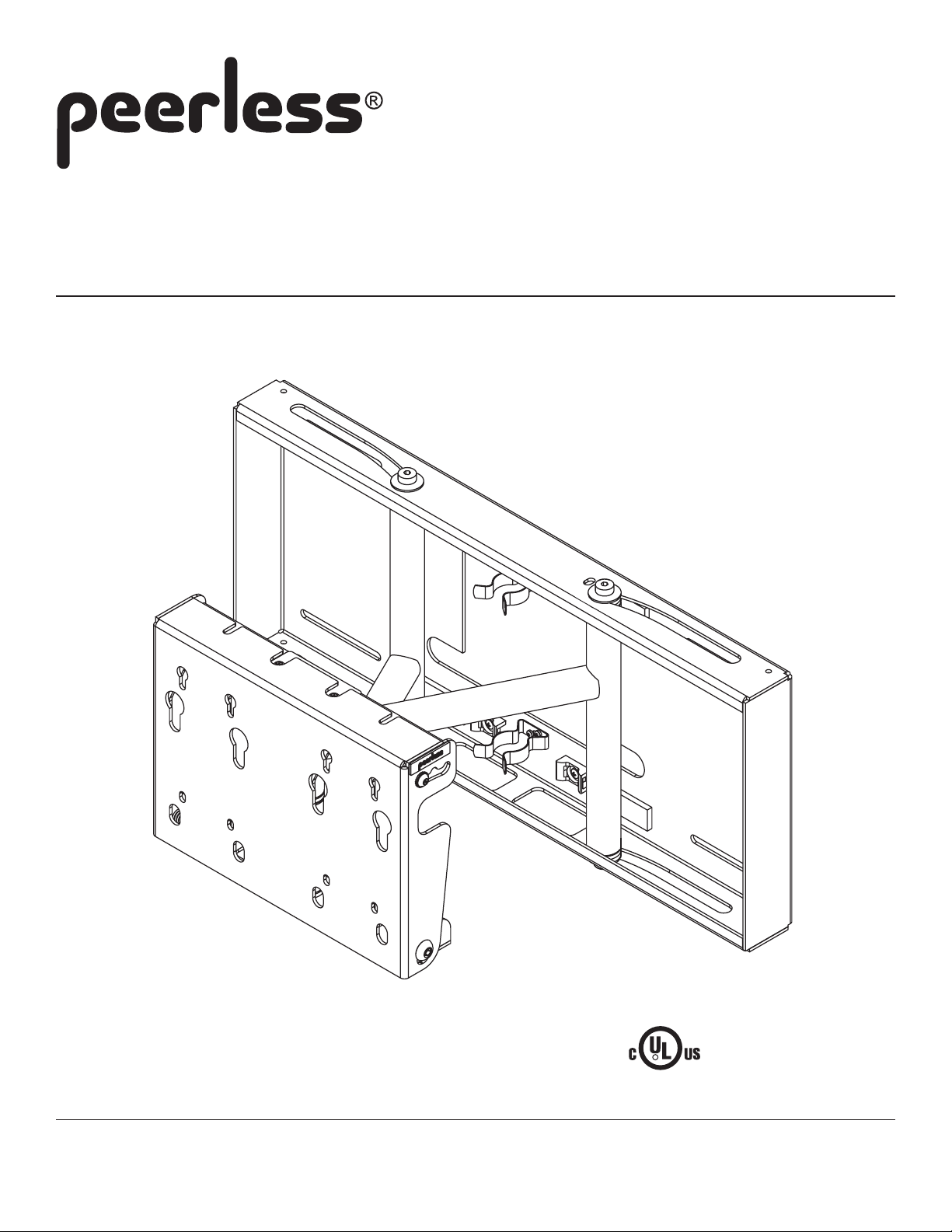
Installation and Assembly:
Flat Panel Pull-out Swiv el W all Mount f or 26" - 58"
Screens
Models: SP 850, SP 850P, SP 850-S, SP 850P-S
This product is intended for use with UL
R
Max Load Capacity: 150 lb (68 kg)
3215 W. North Ave. • Melrose Park, IL 60160 • (800) 729-0307 or (708) 865-8870 • Fax: (708) 865-2941 • www.peerlessmounts.com
ISSUED: 10-12-05 SHEET #: 202-9038-6 05-19-07
Listed products and must be installed by a
qualified professional installer.
Page 2
Note: Read entire instruction sheet before you start installation and assembly.
WARNING
• Do not begin to install your Peerless product until you have read and understood the instructions and warnings
contained in this Installation Sheet. If you have any questions regarding any of the instructions or warnings, please
call Peerless customer care at 1-800-729-0307.
• This product should only be installed by a qualified professional.
• Make sure that the supporting surface will safely support the combined load of the equipment and all attached hardware and components.
• Never exceed the Maximum UL Load Capacity of 150 lb (68 kg).
• If mounting to wood wall studs, make sure that mounting screws are anchored into the center of the studs. Use of an
"edge to edge" stud finder is highly recommended.
• Do not lift more weight than you can handle. Use additional man power or mechanical lifting equipment to safely
handle placement of the screen.
• Tighten screws firmly , but do not overtighten. Overtightening can damage the items, greatly reducing their holding
power.
• This product was designed and intended to be mounted to the following supporting surfaces checked below with the
hardware included in this product as specified in the installation sheet. To mount this product to an alternative supporting surface, contact Peerless customer care at 1 800 865-21 12.
• This product was designed to be installed on the following wall construction only;
WALL CONSTRUCTION ADDITIONAL HARDWARE REQUIRED
x Wood Stud None
x Wood Beam None
x Solid Concrete None
x Cinder Block None
Metal Stud Do not attach except with Peerless accessory kit for metal studs;
Contact Customer Service for Peerless accessory kit for metal studs.
Brick Contact Customer Service
Other or unsure? Contact Customer Service
Tools Needed for Assembly
• stud finder ("edge to edge" stud finder is recommended) • 3/8" socket wrench (3/8" extended driver is recommended)
• phillips screwdriver • drill • 1/4" bit for concrete and cinder block wall • 5/32" bit for wood stud wall
• level • 6 mm allen wrench (if attaching to PLP models)
Table of Contents
Parts List..............................................................................................................................................................................3
Installation to Wood Stud Wall .............................................................................................................................................4
Installation to Solid Concrete and Cinder Block ....................................................................................................................5
Mounting Flat Panel Screen with VESA hole pattern .........................................................................................................6,7
Mounting Flat Panel Screen with Peerless PLP model adapter plate (PLP adapter plates are not UL listed) .......................7
Screen Compatibility Chart .................................................................................................................................................10
For customer care call (800) 729-0307 or (708) 865-8870.
2 of 10
ISSUED: 10-12-05 SHEET #: 202-9038-6 05-19-07
Page 3
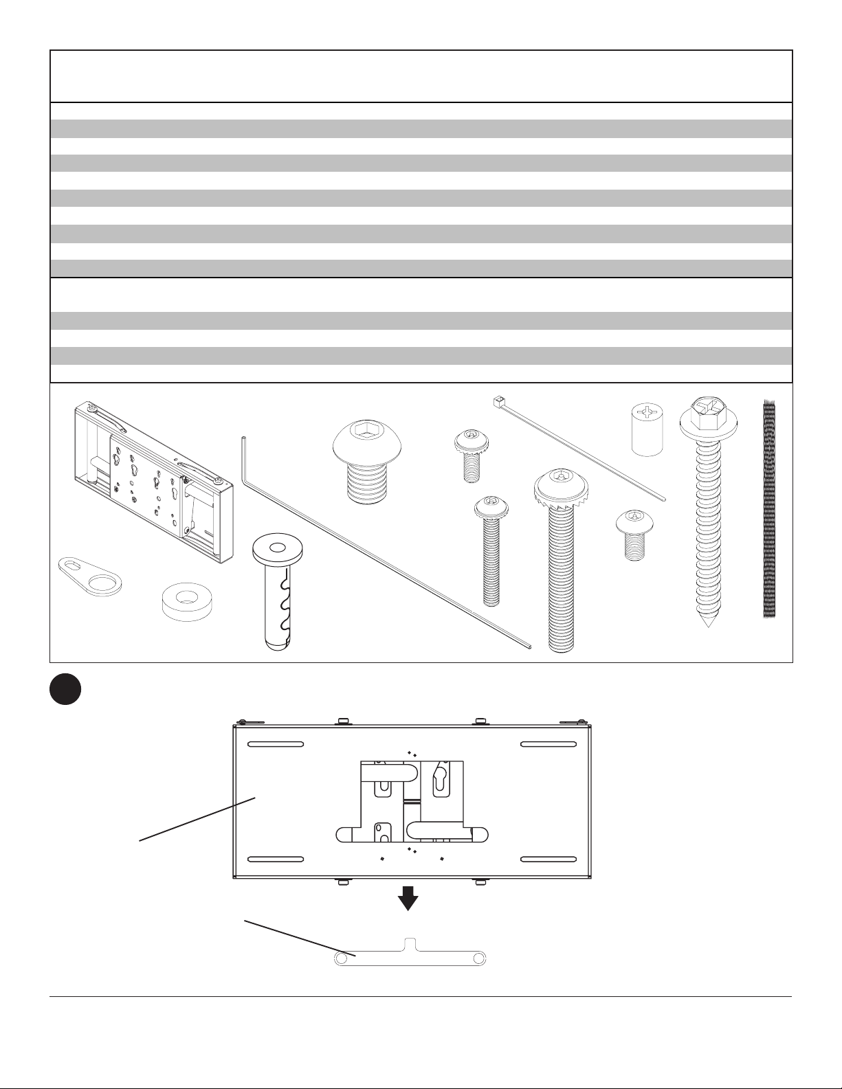
Parts List
De scri ption Qty. Part # Part # Part # Part #
wall mount assem bl y 1 201-0385 201-0386 201-0383 201-0384
A
loc k i ng t ab 1 200-1871 200-1871 200-4871 200-4871
B
.219 ID x . 5 OD x . 125H s pacer 1 540-1032 540-1032 540-1032 540-1032
C
#14 x 2. 5" hex head wood sc rew 4 5S1-015-C03 5S1-015-C03 5S1-015-C03 5S1-015-C03
D
All i gat or® anchor 4 590-0097 590-0097 590-0097 590-0097
E
18" polyester mesh sleeve 2 600-1014 600-1014 600-1014 600-1014
F
cabl e t ie 4 560-9711 560-9711 560-9711 560-9711
G
M10 x 15 mm socket head s crew 4 520-9262 520-9262 520-9262 520-9262
K
.198 x .313 x . 437H retai ning spacer 4 590-5005 590-5005 590-5005 590-5005
L
4 mm securit y allen wrenc h 1 560-1146 n/a 560-1146 n/a
M
M5 x 10 mm screw 5 520-1063 520-1233 520-1063 520-1233
AA
M4 x 12 mm screw 4 510-1079 504-9013 510-1079 504-9013
BB
M4 x 20 mm screw 4 510-1061 504-9020 510-1061 504-9020
CC
M5 x 40 mm screw 1 510-1001 520-1199 510-1001 520-1199
DD
Some parts may appear slightly different than illustrated.
A
K
SP850 SP850P SP850-S SP850P-S
Security Phillips Security Phillips
(not shown) (not shown)
G
L
BB
M
B
E
C
Snap installation tab off of wall mount assembly (A).
1
A
CC
DD
AA
D
F
INSTALLATION TAB
3 of 10
ISSUED: 10-12-05 SHEET #: 202-9038-6 05-19-07
Page 4

Installation to Wood Stud Wall
WARNING
• Make sure that the supporting surface will safely support the combined load of the equipment and all attached
hardware and components.
Using a stud finder, locate the edges of the wood studs used in mounting this product. Use of an edge-to-edge stud
2
finder is highly recommended. Based on its edges and using a level, draw a vertical line down the center of each
stud. Mark a point (point 1) on the right stud centerline where upper right slot will be located. Using a level, mark a
point (point 2) on the left stud centerline level with point 1 as shown in figure 2.1. Drill 5/32" diameter holes 2-1/2"
deep through studs at the two points. Loosely fasten wall mount assembly (A) to wall using two #14 x 2-1/2" wood
screws (D) as shown in figure 2.2. Level, hold, and then tighten screws.
Mark two more points for bottom slots on the right and left stud centerlines. Drill 5/32" diameter holes 2-1/2" deep
through studs at the two points. Using two #14 x 2-1/2" wood screws, fasten bottom of wall mount assembly to wall
as shown in figure 2.3.
Skip to step 3 on page 6.
CL
POINT 2
CL
fig 2.1
CL = stud centerline
WARNING
• Tighten wood screws so that wall plate is firmly
attached, but do not overtighten. Overtightening can
damage the screws, greatly reducing their holding
power.
• Never tighten in excess of 80 in. • lb (9 N.M.).
• Make sure that mounting screws are anchored into
the center of the stud. The use of an "edge to edge"
stud finder is highly recommended.
POINT 1
D
A
fig 2.2
D
A
fig 2.3
4 of 10
ISSUED: 10-12-05 SHEET #: 202-9038-6 05-19-07
Page 5

Installation to Solid Concrete and Cinder Block Wall
WARNING
• When installing Peerless wall mounts on cinder block, verify that you have a minimum of 1-3/8" of actual concrete
thickness in the hole to be used for the concrete anchors. Do not drill into mortar joints! Be sure to mount in a solid
part of the block, generally 1" minimum from the side of the block. Cinder block must meet ASTM C-90 specifications.
It is suggested that a standard electric drill on slow setting is used to drill the hole instead of a hammer drill to avoid
breaking out the back of the hole when entering a void or cavity .
• Concrete must be 2000 psi density minimum. Lighter density concrete may not hold concrete anchor .
• Make sure that the supporting surface will safely support the combined load of the equipment and all attached hardware and components.
Position wall mount assembly (A) at desired position on
2
wall. Use wall mount assembly, making sure that it is
level, as a template to mark holes. Drill four 1/4" (6 mm)
dia. holes to a minimum depth of 2-1/2" (64 mm). Concrete must be 2000 psi density minimum. Insert anchors
(E) in holes flush with wall as shown in figure 2.4. Place
wall mount assembly over anchors and secure with #14 x
2-1/2" (6 mm x 65 mm) wood screws (D) as shown in
figure 2.5. Make sure wall plate is level and tighten all
fasteners.
1
Drill holes and insert anchors
2
A
concrete
wall
E
WARNING
• Tighten wood screws firmly , but do not overtighten.
Overtightening can damage the screws, greatly
reducing their holding power.
• Never tighten in excess of 80 in • lb (9 N.M.).
WARNING
• Concrete anchors are not intended for attachment to
concrete wall covered with a layer of plaster, drywall,
or other finishing material as shown below. If mounting
to concrete wall covered with plaster/drywall is
unavoidable, plaster/drywall (up to 5/8" thick) must be
counterbored as shown below. Be sure concrete
anchors do not pull away from concrete when tightening screws. If plaster/drywall is thicker than
5/8", custom fasteners must be supplied by installer.
INCORRECT
A
concrete
A
CORRECT
concrete
D
Place wall plate (A) over anchors and secure with
screws (D)
3
Tighten all fasteners
fig 2.4
SOLID CONCRETE
E
D
E
CINDER BLOCK
CUT AW A Y VIEW
plaster/
dry wall
plaster/
dry wall
5 of 10
A
fig 2.5
ISSUED: 10-12-05 SHEET #: 202-9038-6 05-19-07
Page 6

Place installation tab over sliding arms of wall mount assembly (A) to lock them in place.
3
INSTALLATION TAB
SLIDING ARM
A
FOR INSTALLING TO VESA 100 MM, 200 MM HOLE PATTERN
WARNING
• If screws don't get three complete turns in the screen inserts or if screws bottom out and adapter plate is still not
tightly secured, damage may occur to screen or product may fail. Contact customer care for correct hardware to use.
Find the VESA® hole pattern as shown in figures 4.1 and 4.2, and attach screen to mounting plate as specified
4
below. Verify that all holes are properly aligned, and then tighten screws. If using security screws, tighten using
security allen wrench (M).
VESA 100 VESA 200
fig. 4.1 fig. 4.2
FOR VESA 100 MOUNTING PATTERN:
Thread two M4 x 12 mm screws (BB), leaving .25" exposed thread, into top holes on back of screen. Hook screen
onto mounting plate, and attach using bottom two M4 x 12 mm screws as shown in figures 4.3 and 4.4. (page 7)
Tighten all four screws.
Note: If screw (BB) is too small to engage threaded inserts, attach mounting plate to back of screen using four M5 x
10 mm screws (AA).
6 of 10
ISSUED: 10-12-05 SHEET #: 202-9038-6 05-19-07
Page 7

FOR VESA 200 MOUNTING PATTERN:
Thread two M4 x 12 mm screws (BB), leaving .25" exposed thread, into top holes on back of screen. Hook screen
onto mounting plate, and attach using two bottom M4 x 12 mm screws as shown in figures 4.3 and 4.4. Tighten all
four screws.
FOR SCREENS WITH VESA MOUNTING PATTERN IN A POCKET:
Thread two retaining spacers (L) onto two M4 x 20 mm screws (CC), leaving .25" exposed thread as shown in figure
4.5. Thread M4 x 20 mm screws with retaining spacers into top holes on back of screen. Hook screen onto mounting
plate, and attach using bottom two M4 x 20 mm screws and retaining spacers as shown in figures 4.3 and 4.4.
Tighten all four screws.
fig. 4.5
For screens with a hole
pattern in a pocket,
spacers (L) go between
mounting plate and
screen.
MOUNTING PLATE
(NOTE: MOUNTING PLA TE
SHOWN WITHOUT FULL
WALL MOUNT ASSEMBL Y
FOR CLARITY)
fig. 4.3
MOUNTING PLATE
(NOTE: MOUNTING PLA TE
SHOWN WITHOUT FULL
WALL MOUNT ASSEMBL Y
FOR CLARITY)
fig. 4.4
Note: Flat panel screen
may appear slightly
different than illustrated.
For screen compatibility please refer to the plasma interface list on our website www.peerlessmounts.com or
call customer care for a screen specific adapter bracket (PLP models).
FOR INST ALLING TO PEERLESS PLP MODEL ADAPTER BRACKET (not UL listed)
Note: Refer to PLP model adapter bracket instruction sheet for attachment of adapter bracket to screen.
Thread two M10 x 15 mm screws (K), leaving .25" exposed thread, into top holes on back of screen. Hook screen
5
onto mounting plate, and attach using two bottom M10 x 15 mm screws as shown in figures 5.7 and 5.8. Tighten
screws using 6 mm allen wrench (not included).
GENERIC ADAPTER
GENERIC
ADAPTER
BRACKET
BRACKET
MOUNTING PLA TE
K
MOUNTING PLATE
(NOTE: MOUNTING PLATE
SHOWN WITHOUT FULL
WALL MOUNT ASSEMBL Y
FOR CLARITY)
fig. 5.7
7 of 10
K
fig. 5.8
ISSUED: 10-12-05 SHEET #: 202-9038-6 05-19-07
Page 8

Slide one mesh sleeve (F) over each cable. Use
6
cable ties (G) to tighten both ends of mesh sleeves
to cables.
Optional: To lock mount in closed position, insert
7
one M5 x 40 mm screw (DD) into tapped hole in
either top or bottom of flat plate.
Note: loop cable ties through cable mounts and
tighten cable and mesh sleeve to cable mounts.
G
CABLE MOUNTS
F
Screen can tilt 5° or 10° forward.
Note: Screen must be securely attached to mounting plate with all fasteners before adjusting tilt.
8
Note: Screen not shown for clarity .
TAPPED HOLE
FLAT
PLA TE
DD
TAPPED HOLE
T o tilt screen 5° forward, lif t and pull mounting plate forward until middle notch rests on M6 screw as shown in figure
8.1. Tighten M6 screw (both sides) and M10 screws (both sides).
T o tilt screen 10° forward, lif t and pull mounting plate forward until rear notch rests on M6 screw as shown in figure
8.2. Tighten M6 screw (both sides) and M10 screws (both sides).
Note: For security models, tighten M6 screw using security allen wrench (M). For all M10 screws, use 6 mm allen
wrench (not included).
M6 SCREW
MOUNTING
PLATE
M10 SCREW
M6 SCREW
MOUNTING
PLA TE
M10 SCREW
5° tilt 10° tilt
fig. 8.1 fig. 8.2
8 of 10
ISSUED: 10-12-05 SHEET #: 202-9038-6 05-19-07
Page 9

Roll can be adjusted 1° clockwise or
9
counterclockwise.
T o adjust roll, loosen screen fasteners slightly,
leaving them snug. Level screen, then tighten screen
fasteners.
NOTE: When adjusting roll, screws should be
retightened as indicated in step 4.
SCREEN FASTENER
Optional: To lock one sliding arm of mount in place,
10
slide locking tab (B) over top or bottom of sliding arm
and attach to mount using one M5 x 10 mm screw
(AA) and one spacer (C).
Note: Screen not shown for clarity .
AA
B
C
SLIDING ARM
9 of 10
ISSUED: 10-12-05 SHEET #: 202-9038-6 05-19-07
Page 10

Screen Compatibility Chart
Man ufa ctu rer Screen Man ufacturer Model
Size
Apex 27" AVL-2776
Dell 26" W2600
Dell 30" W3000
Gateway 26" GTW-L26M103
Gateway 30" GTW-L30M103
Hewlett Packard 30" LC3040N
Hyundai 26" HQL260WR
Hyundai 32" HQL320WR
LG 26" 26LX1D
LG 26" RM-26LZ30
LG 26" RU-26LZ30
LG 26" Z26LZ5R
LG 27" RU-27LZ50C
LG 30" DU-30LZ30
LG 30" L3000H
LG 30" L3020T
LG 30" RU-30LZ50C
LG 32" RU-32LZ30C
LG 32" RU-32LZ50C
Magnavox 26" 26MF605W/17
Magnavox 32" 32MF605W/17
MAXENT 27" MX-27X1
MAXENT 30" MX-30X1
MAXENT 32" MX-32X3
Mitsubishi 30" LT-3020
Mitsubishi 30" LT-3040
Mitsubishi 30" LT-3050
Mitsubishi 30" MLM300
NEC-Mitsubishi 30" LCD3000
NuVision 26" NVX26HDU
NuVision 32" NVX32HDU
Ovideon 27" LC2700w
Ovideon 30" LC3000W
Philips 26" 26MF605W/17
Philips 26" 26PF9966
Philips 30" 300WN5VB
Philips 32" 32MF605W/17
Philips 32" 32PF5320
PixelPro 27" PX-27XP10
PixelPro 30" PX-30XP10
PowerSpec 30" LC30D
Pro View 32" RX-326
Protron 32" PLTV32C
Samsung 26" LN-R2668W
Samsung 26" LN-R267W
Samsung 26" LN-R268W
Samsung 26" LT-P266W
Sceptre 30" X30SV- Naga III
Man ufa ctu rer Screen Man ufacturer Model
Size
Sharp 26" IT-26M1U
Sharp 26" LC-26D5U
Sharp 26" LC-26D7U
Sharp 26" LC-26GA4U
Sharp 26" LC-26GD4U
Sharp 26" LC-26GD6U
Sharp 26" LD-26SH1U
Sharp 30" LC-30HV2U
Sharp 30" LC-30HV4U
Sharp 30" LC-30HV6U
Sony 26" KLV-26HG2
Sony 26" KLVS26A10
Syntax/Olevia 26" LT26HV
Syntax/Olevia 26" LT26HVX
Syntax/Olevia 27" LT27HV
Syntax/Olevia 30" LT30HV
Syntax/Olevia 32" LT32HV
Syntax/Olevia 37" LT37HV
Tatung 27" V27CMTT
Tatung 30" V30CMTT
Toshiba 26" 26HL83
Toshiba 26" 26HL84
Toshiba 32" 32HL84
Viewsonic 27" N2750w
Westinghouse 27" LTV-27w2
Westinghouse 27" W32701
Westinghouse 30" W33000
Westinghouse 30" W33001
Westinghouse 32" LTV-32w1
Westinghouse 37" LVM-37w1
Winbook 32" LC32
Zenith 27" L27W46
10 of 10
All other brand and product names are trademarks or registered trademarks of their respective owners.
ISSUED: 10-12-05 SHEET #: 202-9038-6 05-19-07
© 2007, Peerless Industries, Inc. All rights reserved.
 Loading...