

Page 1
Assembly Instructions - Universal Speaker Mounts
Models:
SPK 811, SPK 81 1W
IMPORTANT! Read entire instruction sheet before you start installation and assembly.
For customer service, call 1-800-729-0307 or 708-865-8870.
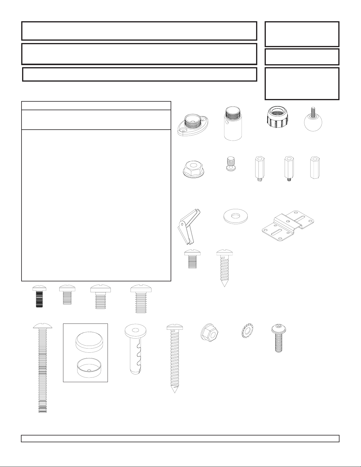
Description
A
mounting base
B
extension
C
cap
D
ball
E
M4 x .7 x 10 mm phillips screw
F
M5 x .8 x 8 mm phillips screw
G
M6 x 1 x 10 mm phillips screw
H
1/4-20 x 1/2 phillips screw
I
10-32 x .313 phillips screw
J
#10 x 3/4 phillips wood screw
K
1/4-20 serrated locknut
L
#10 flat washer
M
1/4-20 keyhole adapter
N
1/4-20 to M5 reducer
O
1/4-20 to M4 reducer
P
1/4-20 coupling
Q
mounting plate
R
toggler
S
#10-24 x 2" phillips screw
T
plastic #10 screw plug
U
concrete anchor
V
#10 x 1 1/2" wood screw
M4 KEPS hex nut
W
M4 serrated washer
X
M4 x 16 mm socket pin screw
Y
Parts List
Qty.
1
1
1
1
4
4
4
4
2
4
2
2
1
1
1
1
1
2
2
2
2
2
2
2
2
SPK 811
590-1144
590-1145
590-1146
590-1147
504-9012
570-0005
520-9401
510-9108
520-1173
500-9006
530-1021
540-9400
580-1026
580-1027
580-1028
580-1029
087-1037
560-9717
520-2078
590-1158
590-0097
510-9163
530-1041
540-1033
510-1087
SPK 811W
590-2144
590-2145
590-2146
590-2147
520-2027
520-9530
520-9524
520-9511
520-2173
500-2014
530-2021
540-9442
580-2026
580-2027
580-2028
580-2029
087-2037
560-9717
520-2078
590-2158
590-0097
500-2002
530-2041
540-2033
510-2087
A B C
K
R
I
MAXIMUM LOAD CAPACITY:
20 lb (9 kg) each mount.
Tools Required: Drill,
screwdriver, two 7/16"
open end wrenches,
channel locks, hammer,
pencil, tape measure, level.
MNO
L
Q
J
D
P
E
F
S
If you are missing a fastener, please contact our customer service department before returning the speaker mounts to store from which they
were purchased.
Visit the Peerless Web Site at www.peerlessmounts.com For customer care call 1-800-729-0307 or 708-865-8870.
GH
T
U
V
1 of 4
W
X
ISSUED:03-26-03 SHEET #: 087-9012-4 06-14-07
Y
Page 2
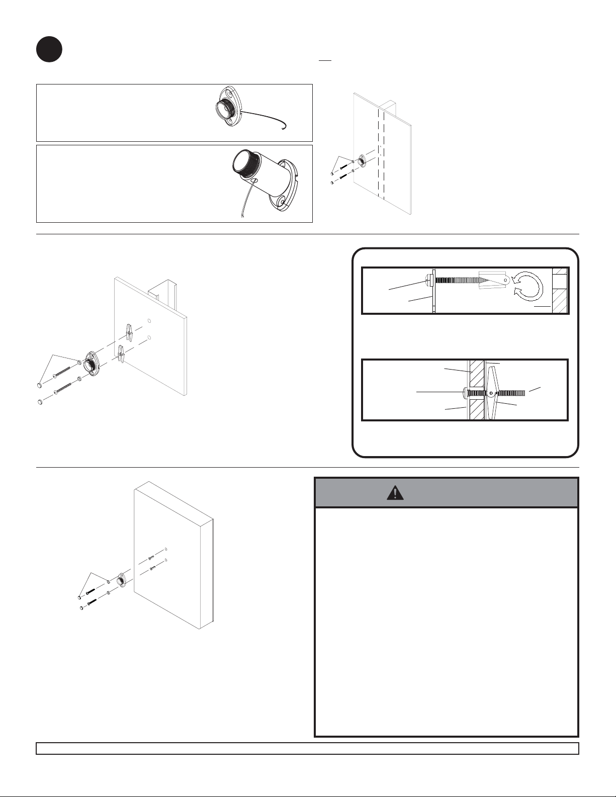
Attachment of Base Unit to Wall or Ceiling
1
Note: Ceiling applications must be mounted to a ceiling joist (NO Drywall Only).
Extension column will be used mostly with ceiling applications.
If bringing wire in from behind wall,
make sure that wires are run through
wire management slot* before mounting
base unit (A) to wall or ceiling.
*
A
When using extension column, be sure to mount
base unit (A) with wire management slot* facing
right so that wire management hole in extension
** is facing down. Remember to run wires
(B)
through wire management hole before mounting
base unit (A) to wall or ceiling.
**
B
*
A
For Attachment to Wood Stud Walls:
Use a stud finder to locate center of
stud. Drill two 3/16" (5 mm) dia. holes to
T
A
V
a minimum depth of 2" (51 mm). Attach
mounting base unit (A) to center of
wood stud using two wood screws (V)
and two plastic screw plugs (T) as
shown left.
IMPORTANT: Make sure wall bracket is
level on wall.
For Attachment to Metal Stud Walls
or Direct Attachment to Drywall for
Speakers Over 10 lb: Use a stud
finder to locate center of stud. Drill two
5/8" (16 mm) dia. holes through metal
stud. Attach mounting base unit (A) to
center of metal stud using two #10-24
T
R
A
S
phillips screws (S), two plastic screw
plugs (T) and two togglers (R) as
shown in DETAIL ONE.
IMPORTANT: Make sure mounting
base (A) is level on wall. Product must
be mounted through drywall that has a
minimum thickness of 1/2" and into
metal studs, 26 gauge or heavier.
Bottom of
plastic screw
plug (T)
A
Place screw (S) through bottom of plastic screw plug (T)
and mounting base (A). Partially fasten toggler (R) to
back of screw. Pivot toggler ends 90° and push through
hole in drywall.
Top of plastic
screw plug (T)
Pull screw back until toggler is flush with metal stud and
hold. Thread screw through with fingers and tighten
securely. Place top of plastic screw plug (T) over screw.
DETAIL ONE
S
Drywall
A
R
Metal Stud
Drywall
R
WARNING
• When installing Peerless wall mounts on cinder block,
verify that you have a minimum of 1 5/8" of actual
concrete surface in the 1/4" diameter hole to be used
T
U
A
V
For Attachment to Concrete or Direct Attachment to Drywall
for Speakers Under 10 lb: Drill one 1/4" (6 mm) dia. hole to a
minimum depth of 2" (51 mm). Insert one anchor (U) in hole flush with
wall. Place mounting base unit (A) over anchor (U) and secure with
one wood screw (V) and one plastic screw plug (T). Make sure wall
bracket is level, mark other hole and repeat steps with other
fasteners. Tighten all fasteners.
IMPORTANT: Make sure wall bracket is level on wall.
2 of 4
Visit the Peerless Web Site at www.peerlessmounts.com For customer care call 1-800-729-0307 or 708-865-8870.
for the concrete anchors. It is suggested that a
standard electric drill on slow setting is used to drill
the hole instead of a hammer drill to avoid breaking out
the back of the hole when entering a void or cavity . Do
not drill into mortar joints!
• Never attach concrete expansion anchors to concrete
covered with plaster, drywall or other finishing material.
If mounting to concrete surfaces covered with a
finishing surface is unavoidable, the finishing surface
must be counterbored.
• Tighten concrete anchor bolt firmly , but do not overtighten. Overtightening can damage the bolt, greatly
reducing its holding power.
• Never tighten in excess of 80 in • lb (9 N.M.).
ISSUED:03-26-03 SHEET #: 087-9012-4 06-14-07
S
Page 3

Note: If you are unable to attach your speaker to the Universal Speaker Mount please contact our customer service department for assistance prior
to returning this product to the store from which it was purchased.
Attachment of Ball and Cap to Speaker
2
For Attachment to Speakers with a Keyhole on Back: Thread
keyhole adapter (M) into coupling (P) a few turns. Insert assembly into
keyhole on back of speaker as shown in DETAIL TWO. Hand tighten
coupling (P) until it fits tightly against back of speaker. Use 7/16” open
end wrench to tighten coupling (P) until it is secured to speaker. Insert
ball (D) through cap (C) and thread into coupling (P). Hand tighten ball (D)
until it is secured to coupling (P).
DETAIL TWO
For Attachment to Speakers with a Single Threaded
Insert: For 1/4-20 size threaded inserts, thread one locknut
(K) halfway onto ball (D). Insert ball (D) through cap (C) and
thread directly into threaded insert on back of speaker.
Tighten locknut (K) until it is securely against back of
speaker. For M5 and M4 size threaded inserts, use reducer
(N) or (O) to thread ball (D) into threaded insert. Note:
Locknut (K) is not used with reducer (N) or (O).
Use reducer
(N) for M5
inserts
Use reducer
(O) for M4
inserts
M
P
C
P
D
Speaker
K
C
D
For Attachment to Speakers with More Than One Threaded Insert: Insert ball (D) through cap (C) and attach mounting plate (Q) using two
serrated locknuts (K) as shown in DETAIL THREE. Attach mounting plate (Q) to speaker using two or four screws (E),(F),(G),(H) or (I) as needed
for speaker threaded insert pattern.
DETAIL THREE
K
K
D
C
Q
Use two 7/16” open end wrenches to
tighten locknuts (K).
DETA IL FOUR
SPEAKER
L
W
Q
For Speakers with Four Threaded Inserts For Speakers with Two Threaded Inserts
M4 screws (E) and 10-32
screws (I) will require
washers (L) when used in
two threaded insert
applications.
Q
E, F, G or H
For Attachment to Speakers with Two Keyholes: Insert ball (D) through cap (C) and attach mounting plate (Q)
using two serrated locknuts (K) as shown in DETAIL THREE. For each keyhole, slide a M4 serrated washer (X) onto
a M4 x 16 mm socket pin screw (Y). Tilt and drop both M4 serrated washer (X) and M4 x 16 mm socket pin screw (Y)
into slot on speaker back and slide into locking position. Place bracket mounting plate (Q) onto M4 x 16 mm socket pin
screws (Y). Fasten #10 flat washer (L) then M4 KEPS hex nut (W) onto each M4 x 16 mm socket pin screws (Y) as
shown in DETAIL FOUR.
For Speakers with Two Keyholes
Q
E, F, G, H or I
W
Q
Y
Y
X
X
L
3 of 4
Visit the Peerless Web Site at www.peerlessmounts.com For customer care call 1-800-729-0307 or 708-865-8870.
ISSUED:03-26-03 SHEET #: 087-9012-4 06-14-07
Page 4

DETAIL FOUR
Q
J
Back of Speaker
Attachment of Ball/Cap and Speaker to Mounting Base or Extension
3
For Attachment to Speakers with
No Threaded Inserts: Insert ball (D)
through cap (C) and attach mounting
plate (Q) using two serrated locknuts
(K) as shown in DETAIL THREE. Use
mounting plate (Q) as a template to
mark four hole centers onto back of
speaker as indicated in DETAIL FOUR.
Using a 5/32" drill bit, drill four pilot
holes into back of speaker. Attach
mounting plate (Q) to speaker using
four #10-3/4" wood screws (J).
Thread ball/cap assembly
onto mounting base (A) or
extension (B) by hand.
For heavier speakers, it
OR
may be necessary to
tighten cap (C) with
channel locks. If so, wrap
a cloth around cap (C) to
prevent damage.
CA CB
WARNING
• In order to adjust speaker, cap must be loosen and re-tightened af ter adjustment. The speaker cannot be adjusted
after the cap has been tightened down. This will cause damage to the mount and speaker .
4 of 4
Visit the Peerless Web Site at www.peerlessmounts.com For customer care call 1-800-729-0307 or 708-865-8870.
All other brand and product names are trademarks or registered trademarks of their respective owners.
ISSUED:03-26-03 SHEET #: 087-9012-4 06-14-07
© 2007, Peerless Industries, Inc. All rights reserved.
 Loading...