

Page 1
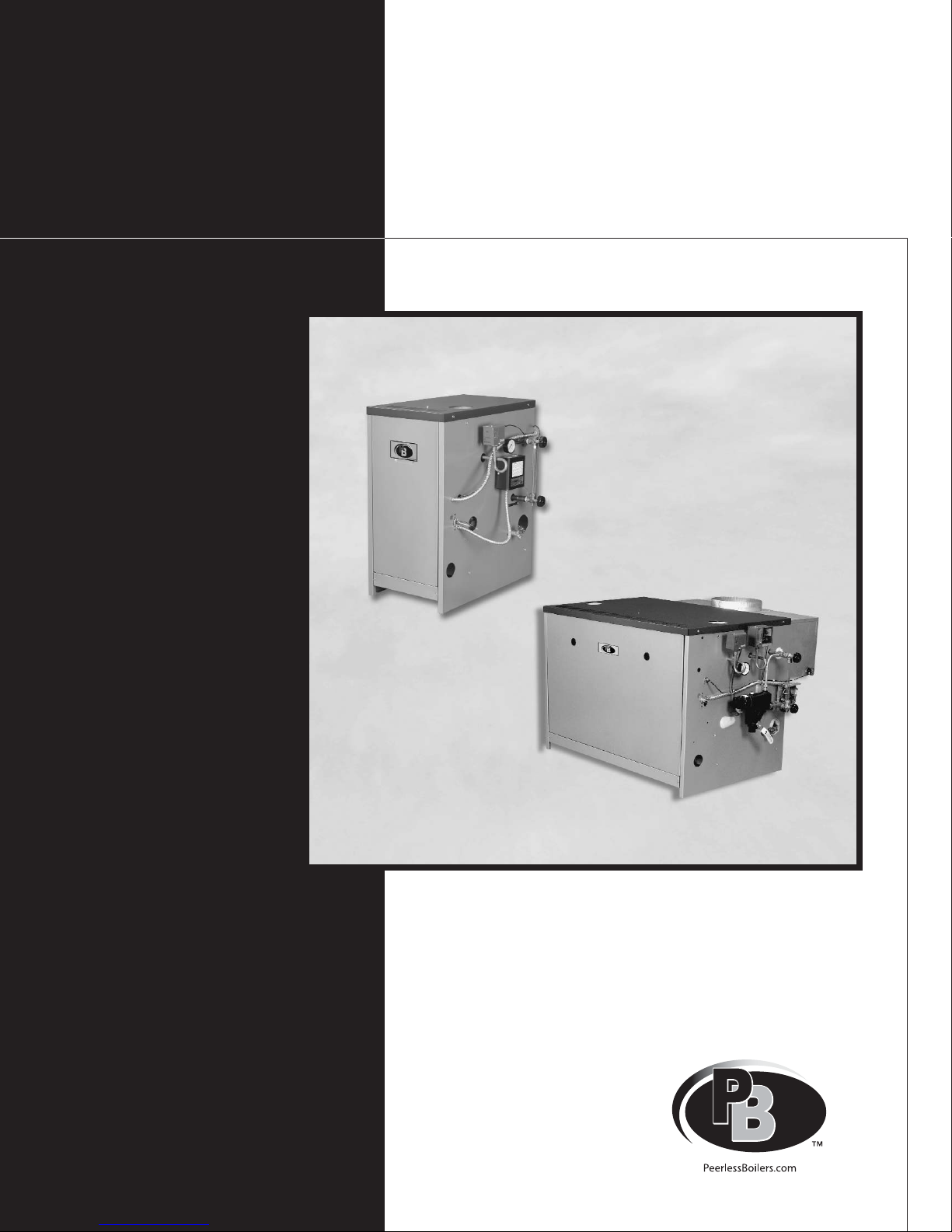
63/64
™
Boilers
Series
Gas
Installation,
Operation &
Maintenance
Manual
Page 2

USING THIS MANUAL 1
A. MANUAL ORGANIZATION . . . . . . . . . . . . . .1
B. SPECIAL ATTENTION BOXES . . . . . . . . . . . .1
1. PREINSTALLATION 2
A. GENERAL . . . . . . . . . . . . . . . . . . . . . . . . . . . .2
B. CODES & REGULATIONS . . . . . . . . . . . . . . . .2
C. ACCESSIBILITY CLEARANCES . . . . . . . . . . .2
D. CLEARANCE FROM COMBUSTIBLE
CONSTRUCTION . . . . . . . . . . . . . . . . . . . . . .2
E. AIR COMBUSTION AND VENTILATION . . . .3
F. INSTALLATION SURVEY . . . . . . . . . . . . . . . .6
G. PLANNING THE LAYOUT . . . . . . . . . . . . . . . .6
2. BOILER PLACEMENT & ASSEMBLY 7
A. PACKAGED BOILER . . . . . . . . . . . . . . . . . . . .7
B. KNOCKDOWN BOILERS – SPLIT BLOCK . . .7
C. KNOCKDOWN BOILERS – ASSEMBLED
BLOCKS . . . . . . . . . . . . . . . . . . . . . . . . . . . . .8
D. KNOCKDOWN BOILERS – CONTROL &
MANIFOLD ASSEMBLY . . . . . . . . . . . . . . . . .8
E. KNOCKDOWN BOILERS – FLUE COLLECTOR
ASSEMBLY . . . . . . . . . . . . . . . . . . . . . . . . . . .8
F. KNOCKDOWN BOILERS – HYDROSTATIC
TESTING . . . . . . . . . . . . . . . . . . . . . . . . . . . . .9
G. KNOCKDOWN BOILERS – ASSEMBLE
JACKET . . . . . . . . . . . . . . . . . . . . . . . . . . . . .9
3. VENTING 11
A. CHIMNEY OR VENT . . . . . . . . . . . . . . . . . . .11
B. AUTOMATIC VENT DAMPER
INSTALLATION – GENERAL . . . . . . . . . . . .11
C. BOILER REMOVAL FROM COMMON
VENTING SYSTEM . . . . . . . . . . . . . . . . . . .12
4. BOILER PIPING 13
A. WATER BOILER PIPING – SINGLE
BOILER . . . . . . . . . . . . . . . . . . . . . . . . . . . . .13
B. WATER BOILER PIPING – MULTIPLE
BOILERS . . . . . . . . . . . . . . . . . . . . . . . . . . . .14
C. STEAM BOILER PIPING – SINGLE
BOILER . . . . . . . . . . . . . . . . . . . . . . . . . . . . .14
D. STEAM BOILER INDIRECT WATER HEATER
PIPING . . . . . . . . . . . . . . . . . . . . . . . . . . . . .15
E. STEAM BOILER PIPING – MULTIPLE
BOILERS . . . . . . . . . . . . . . . . . . . . . . . . . . . .15
5. FUEL PIPING 16
A. INSTALLATION . . . . . . . . . . . . . . . . . . . . . . .16
B. OPERATION . . . . . . . . . . . . . . . . . . . . . . . . .16
6. CONTROLS & TRIM 18
A. WATER BOILER CONTROLS & TRIM . . . . .18
B. STEAM BOILER CONTROLS & TRIM . . . . .19
7. ELECTRICAL 20
A. CONNECT SUPPLY WIRING . . . . . . . . . . . .20
B. MOUNT REMAINING CONTROLS . . . . . . . .20
C. INSTALL CONTROL WIRING . . . . . . . . . . . .21
D. WIRING DIAGRAM INDEX . . . . . . . . . . . . . .21
8. BOILER OPERATION 32
A. SYSTEM INSPECTION . . . . . . . . . . . . . . . .32
B1. FILL THE BOILER (WATER BOILERS) . . . . .32
B2. FILL THE BOILER (STEAM BOILERS) . . . . .32
C. LIGHTING INSTRUCTIONS . . . . . . . . . . . . .32
D. PILOT CHECK . . . . . . . . . . . . . . . . . . . . . . . .32
E. MAIN BURNER CHECK . . . . . . . . . . . . . . . .33
F. CONTROLS CHECK . . . . . . . . . . . . . . . . . . .33
G. PURGING AIR . . . . . . . . . . . . . . . . . . . . . . . .33
H. CHECK SYSTEM PRESSURE . . . . . . . . . . . .33
I. CLEAN THE BOILER . . . . . . . . . . . . . . . . . . .33
J. BOILER SHUT-DOWN . . . . . . . . . . . . . . . . .34
9. MAINTENANCE 39
A. GENERAL . . . . . . . . . . . . . . . . . . . . . . . . . . .40
B. DAILY MAINTENANCE . . . . . . . . . . . . . . . . .40
C. WEEKLY MAINTENANCE . . . . . . . . . . . . . .40
D. MONTHLY MAINTENANCE . . . . . . . . . . . . .40
E. ANNUAL MAINTENANCE . . . . . . . . . . . . . .40
F. AS REQUIRED MAINTENANCE . . . . . . . . . .41
10. TROUBLESHOOTING 42
11. BOILER DIMENSIONS & RATINGS 45
12. REPAIR PARTS 47
TABLE OF CONTENTS
TABLE OF CONTENTS
Page 3
1
USING THIS MANUAL
A. INSTRUCTION MANUALS
The Series 63/64™ Installation, Operation &
Maintenance Manual is divided into four basic sections:
1. Preinstallation (Section 1)
2. Installation (Sections 2 through 8)
3. Start-Up (Section 9)
4. Maintenance (Section 10)
B. SPECIAL ATTENTION BOXES
Throughout this manual special attention boxes are
provided to supplement the instructions and make
special notice of potential hazards. The definition
of each of these categories, in the judgement of
PB Heat, LLC are as follows.
USING THIS MANUAL
Indicates special attention is needed, but not directly
related to potential personal injury or property
damage.
NOTICE
Indicates a condition or hazard which will or can
cause minor personal injury or property damage.
CAUTION
DANGER
Indicates a condition or hazard which will cause
severe personal injury, death or major property
damage.
Indicates a condition or hazard which may cause
severe personal injury, death or major property
damage.
WARNING
Page 4
2
PREINSTALLATION
A. GENERAL
Series 63/64™ boilers are supplied knocked down for field
assembly or completely assembled as packaged boilers.
All items should be inspected for damage upon receipt
and any damage reported to the trucker and wholesaler.
All components should be stored in a clean dry area.
Carefully read these instructions before beginning work.
Understand all aspects of the installation. Contact PB
Heat sales representative or customer service for help in
answering questions.
This boiler must be installed by a qualified contractor.
The boiler warranty may be voided if the boiler is not
installed correctly.
A hot water boiler installed above radiation level or as
required by the Authority having jurisdiction, must be
provided with a low water cut-off device either as part of
the boiler or at the time of installation.
B. CODES & REGULATIONS
1. All work should be performed in strict accordance
with the requirements of state and local regulating
agencies and codes dealing with boiler installations.
2. In the absence of such local requirements the
following should govern.
a. ASME Boiler & Pressure Vessel Code, Section
IV – “Heating Boilers”
b. ASME Boiler & Pressure Vessel Code, Section
VI – “Recommended Rules for the Care and
Operation of Heating Boilers”
c. ANSI Z223.1/NFPA 54 – “National Fuel Gas
Code”
d. ANSI/NFPA 70 – “National Electrical Code”
e. ASME CSD-1 – “Controls & Safety Devices for
Automatically Fired Boilers”
f. ANSI/NFPA 211 – “Chimneys, Fireplaces, vents,
and Solid Fuel Burning Appliances”
3. Where required by the authority having jurisdiction,
the installation must conform to the Standard for
Controls and Safety Devices for Automatically Fired
Boilers, ANSI/ASME CSD-1.
C. ACCESSIBILITY CLEARANCES
The following recommendations allow for reasonable
access to the boiler. Local codes or special conditions
may require greater clearances.
1. For servicing the boiler provide not less than 24"
from the side of the boiler where limit and level
controls are mounted.
2. For servicing the burners provide not less than 24"
from the front of the boiler.
3. The remaining clearances should be 6" from all sides.
D. CLEARANCES FROM COMBUSTIBLE
CONSTRUCTION
Boiler Models 63-03 through 63-06
1. The design of this boiler is certified for alcove
installation with the following clearances to
combustible construction.
a. Sides: 6"
b. Top: 30"
c. Front: 18"
d. Rear: 6"
e. Single Wall Vent Pipe: 6"
Boiler Models 64-07 through 64-12
2. The design of this boiler is certified for installation
with the following clearances to combustible
construction. Boiler must be installed in an area large
in comparison to the boiler.
a. Sides: 24"
b. Top: 30"
c. Front: 18"
d. Rear: 24"
e. Single Wall Vent Pipe: 6"
3. All Models
a. Single wall vent pipe must be at least 6" away
from combustible construction.
b. For installation on non-combustible flooring only.
c. If it is necessary to build a non-combustible floor
pad on top of an existing combustible floor,
construct pad as described in the Installation of
Specific Equipment Chapter of National Fuel Gas
Code Handbook.
1. PREINSTALLATION
Do not install this boiler on carpeting.
WARNING
Do not install this boiler on combustible flooring. Boiler
installation on combustible flooring is a fire hazard.
WARNING
Page 5
E. AIR FOR COMBUSTION AND
VENTILATION
1. Adequate combustion air and ventilation air must be
provided for this appliance in accordance with the
section of the National Fuel Gas Code entitled, “Air
for Combustion and Ventilation” or applicable
provisions of the local building code. Subsections 2
through 8 as follows are based on the National Fuel
Gas Code requirements.
2. Required Combustion Air Volume:
The total required
volume of indoor air is to be the sum of the required
volumes for all appliances located within the space.
Rooms communicating directly with the space in
which the appliances are installed and through
combustion air openings sized as indicated in
Subsection 3 are considered part of the required
volume. The required volume of indoor air is to be
determined by one of two methods.
a. Standard Method: The minimum required
volume of indoor air (room volume) shall be 50
cubic feet per 1000 BTU/Hr (4.8 m
3
/kW). This
method is to be used if the air infiltration rate is
unknown or if the rate of air infiltration is known
to be greater than 0.6 air changes per hour. As
an option, this method may be used if the air
infiltration rate is known to be between 0.6 and
0.4 air changes per hour. If the air infiltration rate
is known to be below 0.4 then the Known Air
Infiltration Rate Method must be used. If the
building in which this appliance is to be installed
is unusually tight, PB Heat recommends that the
air infiltration rate be determined.
b. Known Air Infiltration Rate Method: Where
the air infiltration rate of a structure is known, the
minimum required volume of indoor air for
appliances other than fan assisted and for the
Series 63/64™ Boiler shall be determined as
follows:
where:
I
other
= Input of appliances other than fan
assisted in Btu/hr
ACH = air change per hour (percent of the
volume of the space exchanged per
hour, expressed as a decimal)
For fan assisted appliances, calculate the required
volume of air using the following equation:
I
fan
= Input of the fan assisted appliances in
Btu/hr
Note: These calculations are not to be used for
infiltration rates greater than 0.60 ACH.
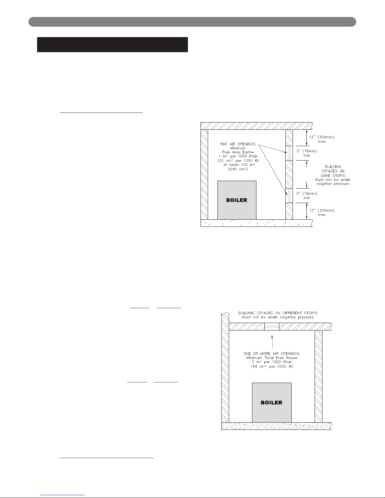
3. Indoor Air Opening Size and Location:
Openings
connecting indoor spaces shall be sized and located
as follows:
a. Combining spaces on the same floor:
Provide two permanent openings communicating
with additional spaces that have a minimum free
area of 1 in
2
per 1000 Btu/hr (22 cm2per 1000 W)
of the total input rating of all gas fired equipment
but not less than 100 in
2
(645 cm2). One
opening is to begin within 12 inches (305 mm)
from the top of the space and the other is to
begin within 12 inches (305 mm) from the floor.
The minimum dimension of either of these
openings shall be 3 inches (76 mm). See Figure
1.1 for an illustration of this arrangement.
b. Combining spaces on different floors:
Provide one or more permanent openings
communicating with additional spaces that have
a total minimum free area of 2 in
2
per 1000
Btu/hr (44 cm
2
per 1000 W) of total input rating
of all equipment. See Figure 1.2 for an
illustration of this arrangement.
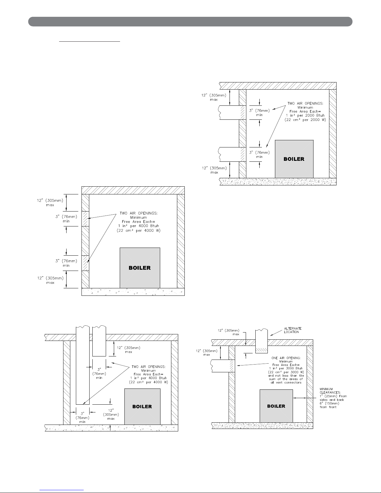
Figure 1.1: Air Openings – All Air from Indoors
on the Same Floor
Figure 1.2: Air Openings – All Air from Indoors
on Different Floors
15 ft
3
I
fan
ACH 1000
Btu
/
hr
Required Volume
fan
=
21 ft
3
I
other
ACH 1000
Btu
/
hr
Required Volume
other
=
⎛
⎜
⎝
⎛
⎜
⎝
⎛
⎜
⎝
⎛
⎜
⎝
3
Page 6
4
PREINSTALLATION
4. Outdoor Combustion Air: Outdoor combustion air is
to be provided through one or two permanent
openings. The minimum dimension of these air
openings is 3 inches (76 mm).
a. Two Permanent Opening Method: Provide
two permanent openings. One opening is to
begin within 12 inches (305 mm) of the top of
the space and the other is to begin within 12
inches (305 mm) of the floor. The openings are
to communicate directly or by ducts with the
outdoors or with spaces that freely communicate
with the outdoors. The size of the openings shall
be determined as follows:
i. Where communicating directly or through
vertical ducts with the outdoors each opening
shall have a minimum free area of 1 in
2
per
4000 Btu/hr (22 cm
2
per 4000 W) of total
input rating for all equipment in the space.
See Figure 1.3 for openings directly
communicating with the outdoors or Figure
1.4 for openings connected by ducts to the
outdoors.
ii. Where communicating with the outdoors
through horizontal ducts, each opening shall
have a minimum free area of 1 in
2
per 2000
Btu/hr (22 cm
2
per 2000 W) of total rated
input for all appliances in the space. See
Figure 1.5.
b. One Permanent Opening Method: Provide
one permanent opening beginning within 12
inches (305 mm) of the top of the space. The
opening shall communicate directly with the
outdoors, communicate through a vertical or
horizontal duct, or communicate with a space
that freely communicates with the outdoors. The
opening shall have a minimum free area of 1 in
2
per 3000 Btu/hr of total rated input for all
appliances in the space and not less than the
sum of the cross-sectional areas of all vent
connectors in the space. The gas-fired equipment
shall have clearances of at least 1 inch (25 mm)
from the sides and back and 6 inches (150 mm)
from the front of the appliance. See Figure 1.6
for this arrangement.
Figure 1.4: Air Openings – All Air from Outdoors
through Vertical Ducts
Figure 1.5: Air Openings – All Air from Outdoors
through Horizontal Ducts
Figure 1.6: Air Openings – All Air from Outdoors
through One Opening
Figure 1.3: Air Openings – All Air Directly from
Outdoors
Page 7

5
5. Combination Indoor and Outdoor Combustion Air: If
the required volume of indoor air exceeds the
available indoor air volume, outdoor air openings or
ducts may be used to supplement the available
indoor air provided:
a. The size and location of the indoor openings
comply with Subsection 3.
b. The outdoor openings are to be located in
accordance with Subsection 4.
c. The size of the outdoor openings are to be sized
as follows:
where:
A
req
= minimum area of outdoor openings.
A
full
= full size of outdoor openings calculated
in accordance with Subsection 4.
V
avail
= available indoor air volume
V
req
= required indoor air volume
6. Engineered Installations:
Engineered combustion air
installations shall provide an adequate supply of
combustion, ventilation, and dilution air and shall be
approved by the authority having jurisdiction.
7. Mechanical Combustion Air Supply:
a. In installations where all combustion air is
provided by a mechanical air supply system, the
combustion air shall be supplied from the
outdoors at the minimum rate of 0.35 ft
3
/min per
1000 Btu/hr (0.034 m
3
/min per 1000 W) of the
total rated input of all appliances in the space.
b. In installations where exhaust fans are installed,
additional air shall be provided to replace the
exhaust air.
c. Each of the appliances served shall be
interlocked to the mechanical air supply to
prevent main burner operation when the
mechanical air supply system is not in operation.
d. In buildings where the combustion air is provided
by the mechanical ventilation system, the system
shall provide the specified combustion air rate in
addition to the required ventilation air.
8. Louvers & Grills:
a. The required size of openings for combustion,
ventilation, and dilution air shall be based on the
net free area of each opening.
i. Where the free area through a louver or grille
is known, it shall be used in calculating the
opening size required to provide the free area
specified.
ii. Where the free area through a louver or grille
is not known, it shall be assumed that wooden
louvers will have 25% free area and metal
louvers and grilles will have 75% free area.
iii. Nonmotorized dampers shall be fixed in the
open position.
b. Motorized dampers shall be interlocked with the
equipment so that they are proven in the full
open position prior to ignition and during
operation of the main burner.
i. The interlock shall prevent the main burner
from igniting if the damper fails to open
during burner startup.
ii. The interlock shall shut down the burner if
the damper closes during burner operation.
9. Combustion Air Ducts
a. Ducts shall be constructed of galvanized steel or
an equivalent corrosion- resistant material.
b. Ducts shall terminate in an unobstructed space,
allowing free movement of combustion air to the
appliances.
c. Ducts shall serve a single space.
d. Ducts shall not serve both upper and lower
combustion air openings where both such
openings are used. The separation between ducts
serving upper and lower combustion air
openings shall be maintained to the source of
combustion air.
e. Ducts shall not be screened where terminating in
an attic space.
f. Horizontal upper combustion air ducts shall not
slope downward toward the source of the
combustion air.
g. The remaining space surrounding a chimney
liner, gas vent, special gas vent, or plastic piping
installed within a masonry, metal, or factory built
chimney shall not be used to supply combustion
air.
h. Combustion air intake openings located on the
exterior of buildings shall have the lowest side of
the combustion air intake opening at least 12
inches (305 mm) above grade.
V
avail
1 –
V
req
A
req
= A
full
x
⎛
⎜
⎝
⎛
⎜
⎝
Page 8

6
F. INSTALLATION SURVEY
For new and existing installations, a Water Installation
Survey or a Steam Installation Survey is available from
PB Heat, LLC. The surveys will provide information on
how the boiler works with your specific system and will
provide an overview of boiler system operation in
general.
You can also use this survey to locate system problems
which will have to be corrected. To obtain copies of
these Surveys, contact your PB Heat representative or
download them from PeerlessBoilers.com.
G. PLANNING THE LAYOUT
Prepare sketches and notes of the layout to minimize the
possibility of interferences with new or existing
equipment, piping, venting and wiring.
PREINSTALLATION
Liquefied Petroleum (LP) is heavier than air and may
collect or “pool” in a low area in the event of a leak
from defective equipment. This gas may then ignite,
resulting in a fire or explosion.
WARNING
Page 9
7
BOILER PLACEMENT & ASSEMBLY
A. PACKAGED BOILER
1. Remove the crate top and sides and remove any
loose cartons.
2. Lift the boiler from the crate pallet. Move the boiler to
the location determined in Chapter 1: Pre-installation.
3. Proceed to Chapter 3: Piping the Boiler.
B. KNOCKDOWN BOILERS – SPLIT BLOCK
ASSEMBLY MODELS 64-07 TO 64-12
1. The boiler sections and base on Model 63-03 to 63-06
are factory assembled. If the boiler is 63-03 through
63-06 begin assembly as described in step 2.C,
Knockdown Boilers: Assembled Blocks.
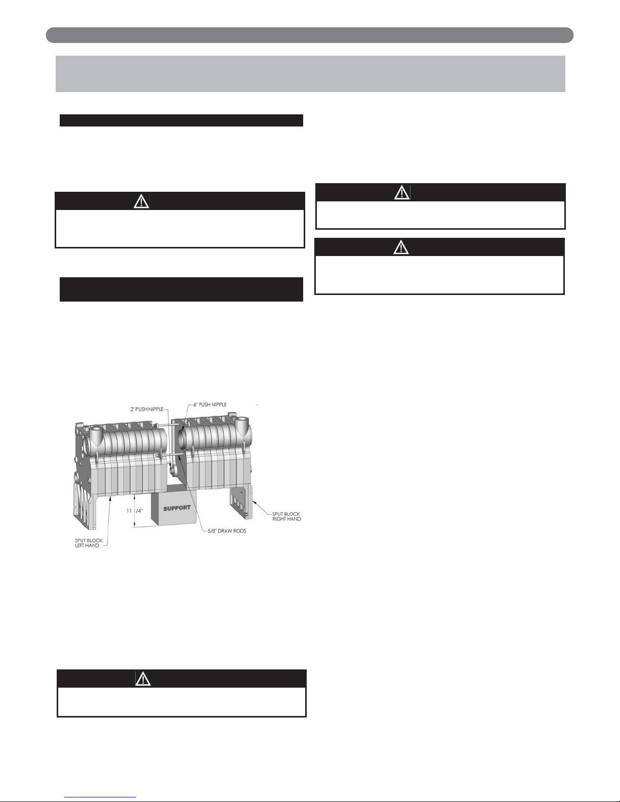
2. Move each block of cast iron sections off of the
shipping pallets and support them as shown in
Figure 2.1.
3. Clean nipple ports using a wire brush. Make certain
there are no burrs around the outside edge of the ports.
If necessary, remove any burrs on the edges using a
round file (be careful not to score the nipple port).
4. Spread a thin coat of TFE TITE Nipple Sealant in
the nipple ports.
5. Insert the push nipples into the nipple ports of one of
the split block ends. Make sure the nipples are clean
and free of burrs. Use a block of wood to protect the
surface of the nipple while setting the nipple into the
nipple port with a hammer. Assure that the nipple is
firmly seated in the nipple port before proceeding.
6. Apply silicone sealant to the rope groove to hold the
rope in place during assembly. Press 1/2" diameter
rope into the rope groove.
7. Assure the nipples are perpendicular to the sections
and that the blocks are aligned properly.
8. Insert draw rods through the lugs provided on the
mating intermediate sections. Use 5/8" draw rods as
shown in Figure 2.1.
9. Before starting to draw the sections together, apply
lubricating oil to the threads.
10. Tighten the hex nuts and draw the boiler sections
together evenly until the small pads on each of the
mating sections are in contact:
·
Periodically measure the gap at all four corners
of the section to make sure the sections are
drawing together evenly – gaps measured at
all four corners should not vary more than
1/8". Turn wrench no more than 3-4 times before
moving to the next nut (this equates to about an
1/8" draw-up).
·
Using similar torque on each nut, gradually
increase the torque as the sections are drawn
closer together. Maximum allowable torque
on the draw rod nuts is 80 foot-pounds.
Typically only 30 to 60 foot-pounds is required to
pull together evenly drawn sections.
·
If one corner resists moving, loosen the draw
rods on the other corners to help pull the subject
corner into proper alignment.
2. BOILER PLACEMENT & ASSEMBLY
Never apply nipple sealer on the nipples. Apply only
in nipple ports.
NOTICE
Be careful not to damage the burner tray when
removing the boiler from the pallet. If necessary,
remove the burner tray before moving the boiler.
NOTICE
Figure 2.1: Block Assembly
Never hit the nipple directly with a hammer. This will
damage the nipple and cause leaks.
NOTICE
If the nipple is not fully seated in the nipple port,
damage to the nipple may occur when the sections
are drawn together.
NOTICE
Page 10
8
BOILER PLACEMENT & ASSEMBLY
11. If the sections do not draw together using the torque
specified above, the block must be separated and the
nipples replaced before reassembly is attempted.
12. The sections may alternatively be drawn together
using long 5/8" rods along with cast iron washers
through the nipple ports. Two large cast iron washers
(51163), two small cast iron washers (51165) and
two long 5/8" NPT rods are required (not provided).
Do not attempt to draw sections together without the
cast iron washers.
C. KNOCKDOWN BOILERS: ASSEMBLED
BLOCKS
1. If shipping pallet is still attached, move the
assembled block off of the pallet.
2. Move the assembled block to the location determined
in Chapter 1: Pre-installation. The location should
be on a level foundation as near to the chimney as
possible and centralized with respect to the heating
system.
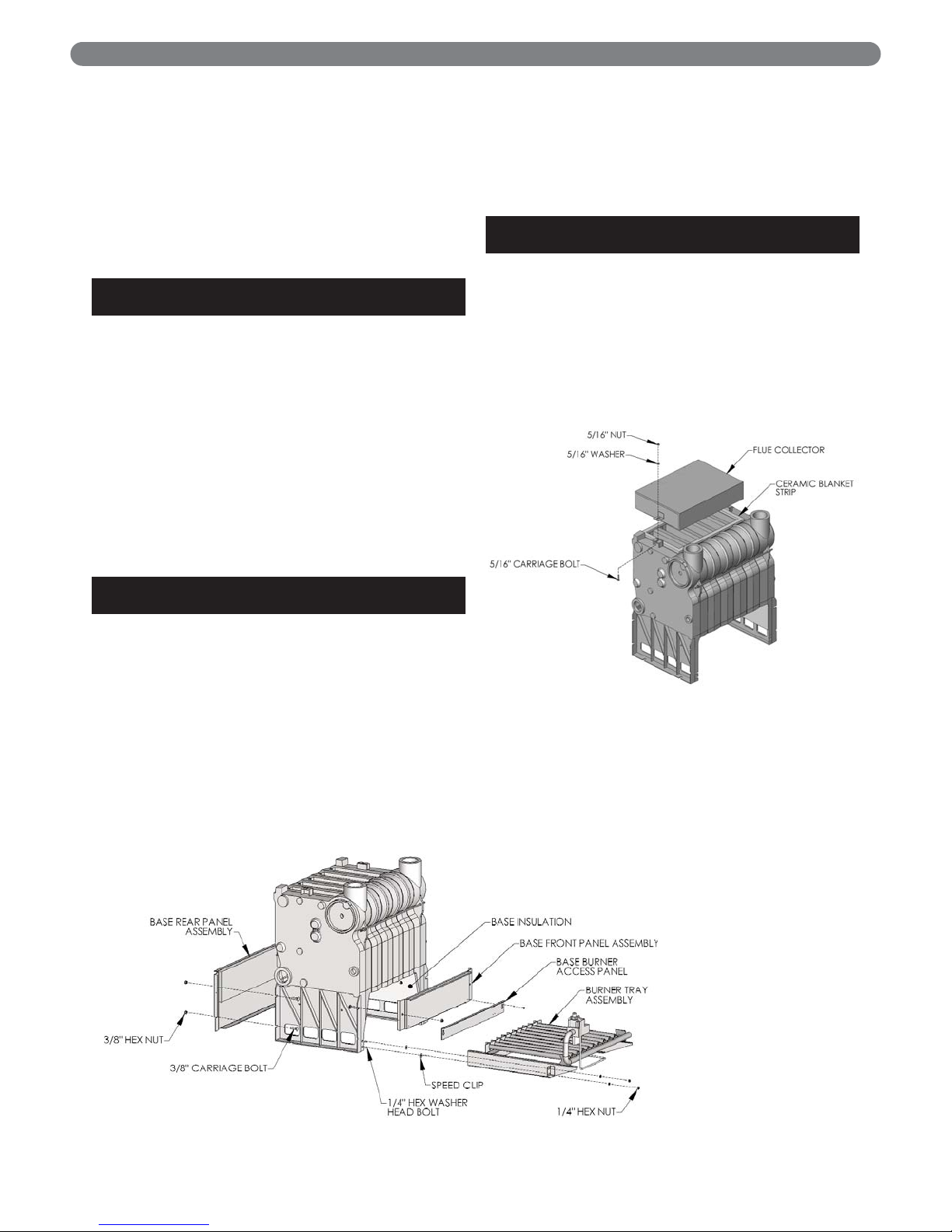
3. Attach the base front/rear insulated panels to the cast
iron block assembly as shown in Figure 2.2 using
3/8" carriage bolts and 3/8" hex nuts.
4. Attach the base lower rear panel to the cast iron block
assembly using 3/8" carriage bolts and hex nuts.
D. KNOCKDOWN BOILERS: CONTROL &
MANIFOLD ASSEMBLY
1. Remove the burner tray assembly from the burner
and controls carton.
2. Check burners to assure that they are seated
correctly in the burner tray rear support.
3. For Series 64™ boilers, assemble the 90° elbow and
return bend to the manifold assembly.
4. Remove the gas valve manifold components from
the burner tray and controls carton and connect
them to the burner manifold. Refer to Figure 5.2
through 5.5 in Section 5 for the specific Gas Train
Manifold Configuration.
5. Slide the burner tray under the cast iron block
assembly and attach to the end sections using the 1/4"
carriage bolts and nuts provided. (See Figure 2.2).
6. Attach the base burner access panel to the base front
panel assembly with two #10 x 1/2" sheet metal
screws (See Figure 2.2).
E. KNOCKDOWN BOILERS: FLUE
COLLECTOR ASSEMBLY
1. Remove the flue collector and ceramic blanket strip
insulation from burner and controls carton.
2. Lay the ceramic blanket strip on top of the boiler
using care not to block any flue passageways.
3. Insert the two 1/4"-20 carriage bolts provided with
boiler into the lugs on top of the boiler end sections
as shown in Figure 2.3.
4. Attach the flue collector to the bolts with the flat
washers and hex nuts provided. Tighten the nuts
snugly.
Figure 2.3: Flue Collector Attachment
Figure 2.2: Base Panel Attachment
Page 11
9
F. KNOCKDOWN BOILER: HYDROSTATIC
TESTING
1. Install the pressure gauge and drain valve in the right
hand end section.
2. Install a water supply line with a shut-off valve in the
right hand end section.
3. Install an air vent valve on the boiler relief valve
connection.
4. Plug all open tappings in the boiler.
5. Fill the boiler with water, venting air from the top of
the unit as the water level rises.
6. Pressurize the boiler from 75 to 85 psig. Do not
exceed 85 psig.
7. Maintain pressure while inspecting the boiler
thoroughly for leaks.
8. After inspection is complete, drain the boiler and
remove plugs from tappings that are to be used.
G. KNOCKDOWN BOILER: ASSEMBLE
JACKET
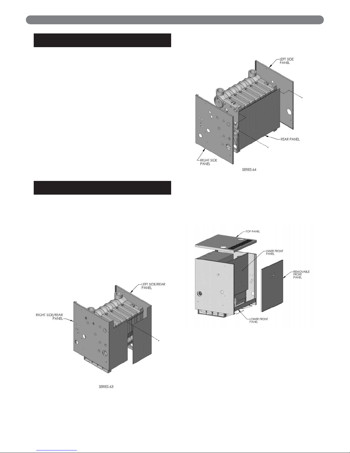
1. The Series 63™ boilers employ a wrap-around style
jacket while the Series 64™ boilers use an individual
back panel.
2. Align the clearance holes on the side panels with the
mounting holes in the base front & back plates and
attach with #10 x 1/2" sheet metal screws.
3. Wrap-Around Jacket: Bend the side jacket panels
at the perforations to form the back of the jacket.
The left side should overlap the right for proper
attachment. Connect the two panels with three
#10 x 1/2" sheet metal screws. See Figure 2.4.
4. Back Panel Jacket: Position the back jacket panel
inside the flange of the side jacket panels and attach it
with six #10 x 1/2" sheet metal screws. See Figure 2.5.
5. Position the Inner Front Panel between the side
panels and align the mounting holes on the side
flanges with the clearance holes on the side panels.
Attach with four #10 x 1/2" sheet metal screws
provided. See Figure 2.6.
6. Attach the Lower Front Panel to the bottom front of
the side Jacket Panels with two #10 x 1/2" sheet
metal screws. See Figure 2.6.
BOILER PLACEMENT & ASSEMBLY
Figure 2.4: Jacket Assembly, Series 63™ Boilers
Figure 2.5: Jacket Assembly, Series 64™ Boilers
Figure 2.6: Jacket Panel Attachment
Page 12
10
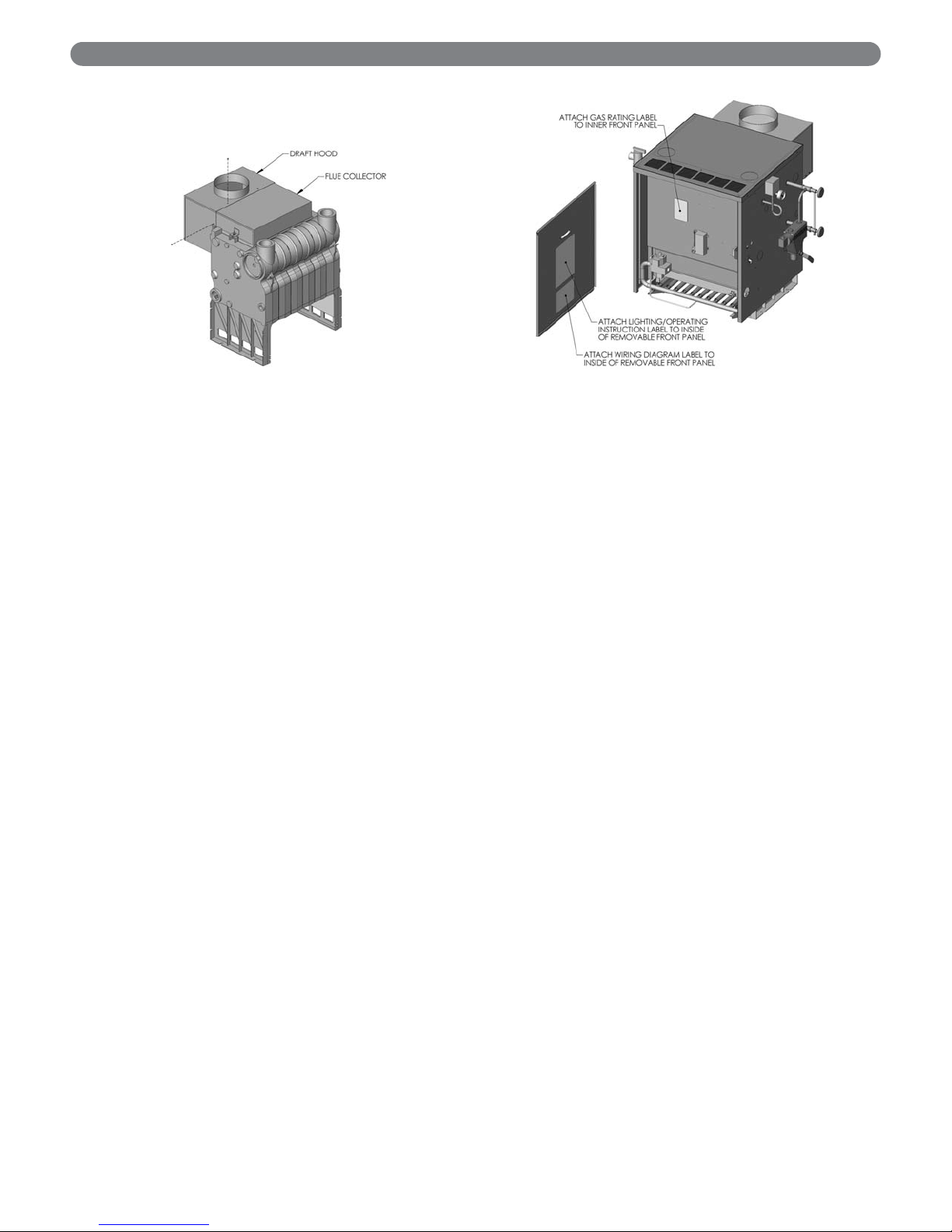
7. Attach the Draft Hood to the Flue Collector using
#10 x 1/2" sheet metal screws provided. Refer to
Figure 2.7.
8. Position the Top Jacket Panel so that the flanges
overlap the Side Jacket Panels and the air louvers are
at the front of the boiler. Attach with six #10 x 1/2"
sheet metal screws. See Figure 2.6.
9. Remove the following data plates or labels from the
manila envelope that contains the Instruction
Manual:
- Boiler Rating Label
- Lighting/Operating Instruction Label
- Wiring Diagram Label
Attach labels as shown in Figure 2.8.
10. Insert the top edge of the Front Jacket Panel beneath
front flange of the Top Jacket Panel and against the
top of the Lower Front Panel.
Figure 2.7: Draft Hood Attachment
Figure 2.8: Label & Rating Plate Locations
BOILER PLACEMENT & ASSEMBLY
Page 13
11
A. CHIMNEY OR VENT
1. Inspect the existing chimney or vent system. Make
sure it is in good condition. Inspect chimney liner
and repair or replace if necessary.
2. The vent system and installation must be in
accordance with Venting of Equipment chapter of
the current edition of the National Fuel Gas Code,
ANSI Z223.1/NFPA 54, or applicable provisions of
the local building codes.
3. Chimney/Vent Operation: The vent system must be
sized and installed to provide the draft needed to
remove all combustion products. If the vent system
does not provide enough draft, combustion products
will spill into the building from the draft hood relief
opening. If spillage of combustion products occurs,
check the vent system, the combustion and
ventilation openings and make sure the boiler room
is never under negative pressure.
4. Vent Connection to Boiler:
a. Support the weight of the vent system
independently of the boiler draft hood. The draft
hood is not designed to carry structural loading.
b. Provide support of the vent connector
(breeching) at maximum 12 foot intervals to
prevent sagging and to provide a minimum
upward slope of 1/4" per foot.
c. Do not connect the vent for this boiler into any
vent system which operates with positive
pressure.
d. The vent connector must be single wall steel or
Type B double wall vent pipe. The vent
connector must be Type B double wall if it is
located in or passes through cold areas. The vent
connector must extend into, but not beyond, the
inside wall of the chimney.
B. AUTOMATIC VENT DAMPER
INSTALLATION – GENERAL
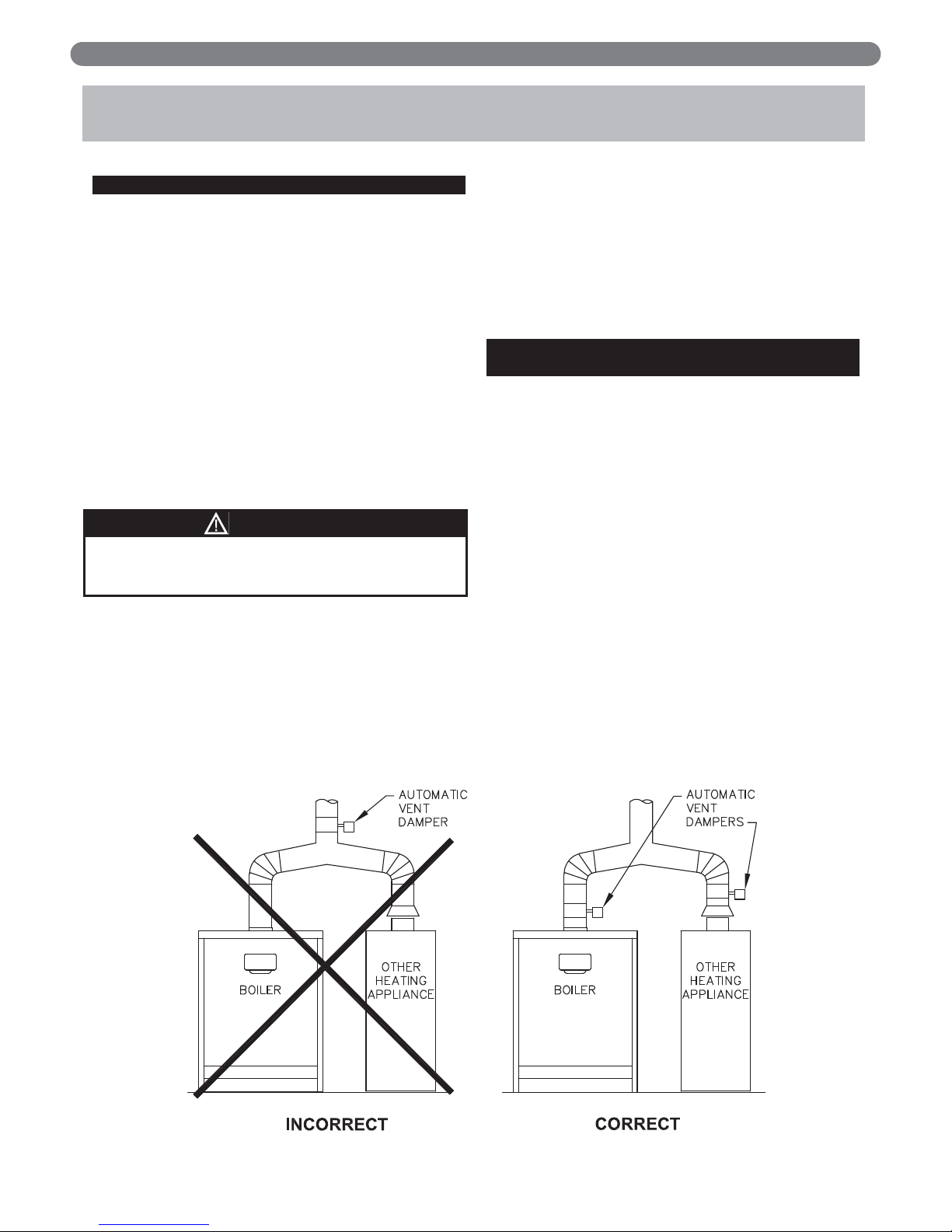
1. Do not use one vent damper to control two or more
heating appliances. See Figure 3.1.
2. Follow these and the installation instructions
included with the vent damper. Observe the cautions
and warnings that accompany all instructions.
3. Provide minimum 6 inch (152 mm) clearance
between automatic vent damper and combustible
construction. Increase clearance if required by vent
damper manufacturer’s instructions. Provide
adequate space for vent damper access and service.
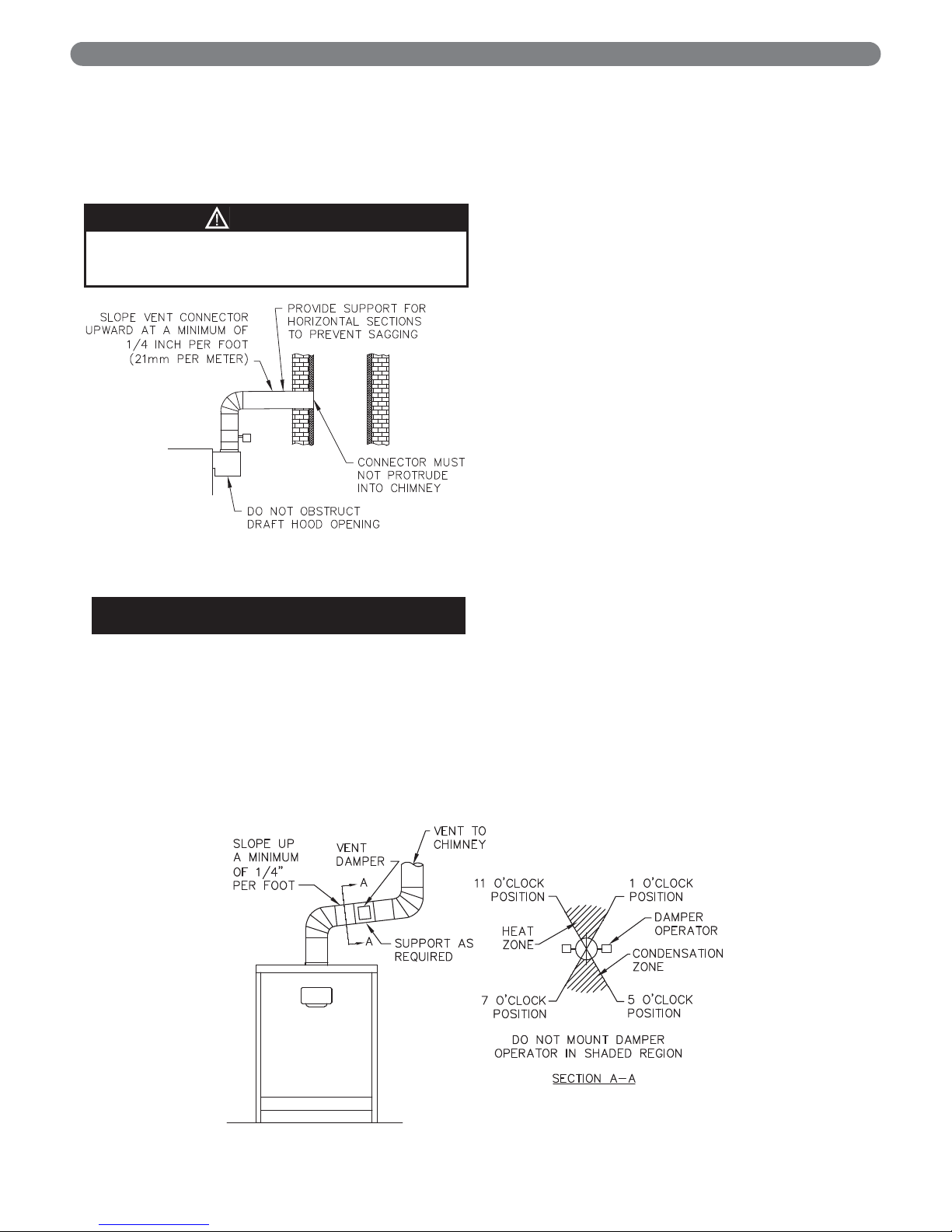
4. The automatic vent damper can be mounted directly
onto the draft hood outlet or in vent piping close to
the boiler.
See Figure 3.2 for installation with vent damper
mounted in vertical position. See Figure 3.3 for
installation with vent damper mounted in horizontal
position. Mount the unit to avoid excessive heat on
the operator or condensation drips into the operator.
Figure 3.1: Venting Multiple Appliances
Failure to provide adequate venting can result in
severe personal injury or death.
WARNING
3. VENTING
Page 14
12
VENTING
a. Orient the vent damper operator to facilitate
connection of the vent damper harness to
knockout on right side of boiler.
b. Orient vent damper direction arrow in direction
of vent gas flow. Direction arrow must be visible
from front of boiler.
C. BOILER REMOVAL FROM COMMON
VENTING SYSTEM
When an existing boiler is removed from a common
venting system, the common venting system is likely to
be too large for proper venting of the remaining
appliances connected to it.
At the time of removal of an existing boiler, follow these
steps with each appliance remaining connected to the
common venting system placed in operation, while the
other appliances remaining connected to the common
venting system are not in operation:
a. Seal any unused openings in the common venting
system.
b. Visually inspect the venting system for proper size
and horizontal pitch and determine there is no
blockage or restriction, leakage, corrosion and other
deficiencies which could cause an unsafe condition.
c. Insofar as is practical, close all building doors and
windows and all doors between the space in which
the appliances remaining connected to the common
venting system are located and other spaces of the
building. Turn on any clothes dryers and any
appliance not connected to common venting system.
Turn on any exhaust fans, such as range hoods and
bathroom exhausts, so they will operate at maximum
speed. Do not operate a summer exhaust fan. Close
fireplace dampers.
d. Place in operation the appliance being inspected.
Follow the lighting instructions. Adjust thermostat so
appliance will operate continuously.
e. Test for spillage at the draft hood relief opening after
5 minutes of main burner operation. Use the flame
of a match or candle, or smoke from a cigarette,
cigar, or pipe.
f. After it has been determined that each appliance
remaining connected to the common venting system
properly vents when tested as outlined above, return
doors, windows, exhaust fans, fireplace dampers and
any other gas-burning appliance to their previous
conditions of use.
g. Any improper operation of the common venting
system should be corrected so that the installation
conforms with the National Fuel Gas Code, ANSI
Z223.1/NFPA 54 or CAN/CGA B149 Installation
Codes. When resizing any portion of the common
venting system, the common venting system should
be resized to approach minimum size as determined
using the appropriate tables located in the chapter
“Sizing of Category I Venting Systems,” of the
National Fuel Gas Code, ANSI Z223.1/NFPA 54 or
CAN/CGA B149 Installation codes.
Figure 3.2: Venting with Vent Damper in
Vertical Position
Figure 3.3: Venting with Vent Damper in Horizontal Position
Damper must be in open position when appliance
main burner is operating.
CAUTION
Page 15
13
BOILER PIPING
A. WATER BOILER PIPING – SINGLE
BOILER
1. Refer to the PB Heat Water Installation Survey and
Hydronics Institute Residential Hydronic Heating
Installation Design Guide.
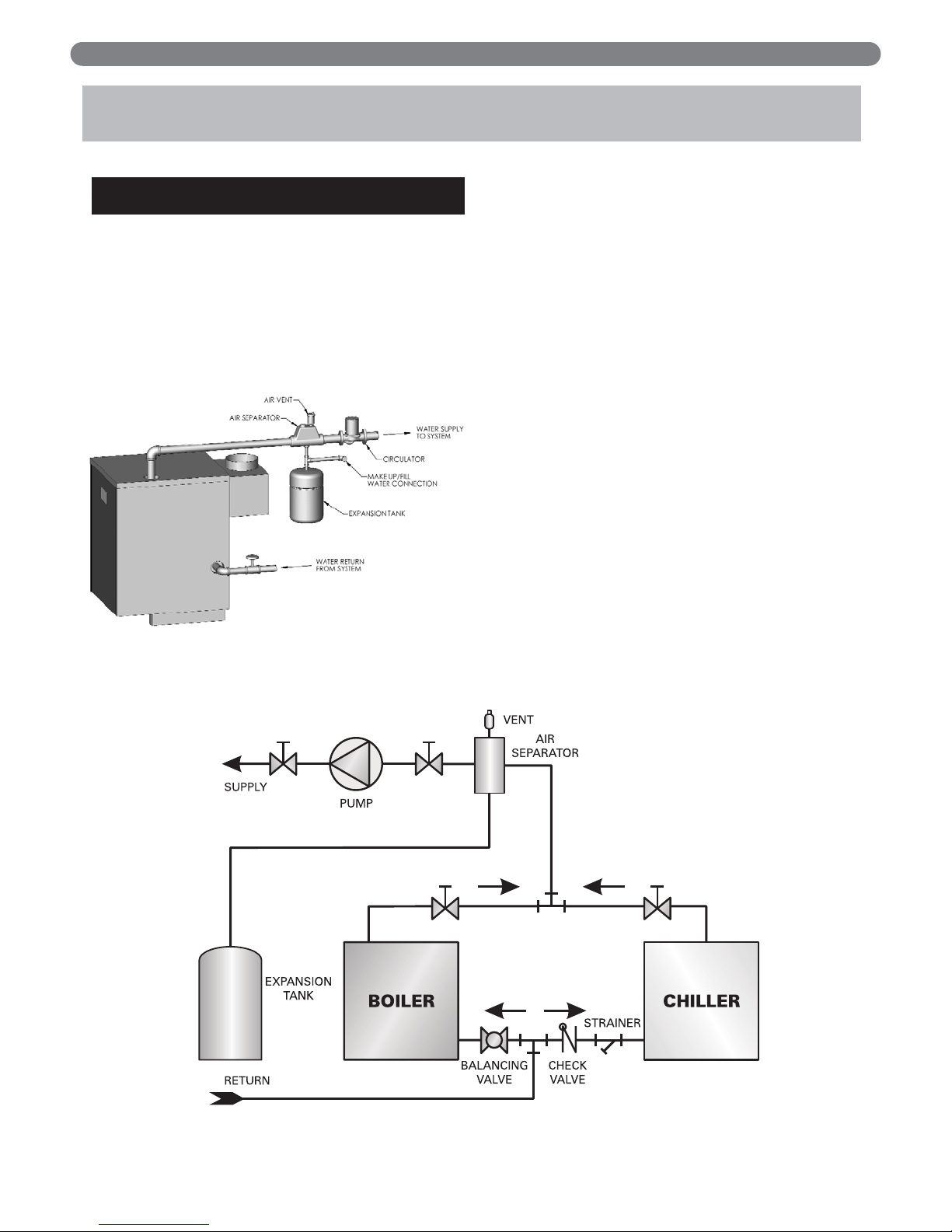
2. Figure 4.1 shows typical supply and return piping for
a boiler system. If the system expansion tank is
located on the boiler loop, it should be located on the
supply side of the boiler with the system circulator
pumping away from the expansion tank connection.
3. If the boiler is piped in a secondary loop separate
from the system expansion tank, the boiler circulator
should be located on the return side of the boiler
pumping away from the common piping.
4. Return water should not reach the boiler return
connection at less than 130°F under normal
operating conditions. If the system return
temperature is expected to be below 130°F the boiler
should be piped in a secondary loop with a bypass
arrangement to assure water returning to the boiler is
above 130°F. For more information on bypass piping
consult the PB Heat Water Installation Survey.
5. If the boiler and distribution system is used in
conjunction with a refrigeration system, pipe the
chilled medium in parallel with the boiler and
provide isolation valves to prevent chilled water form
entering the boiler. See Figure 4.2.
6. If the boiler is connected to a heating coil in a forced
air combination heating and cooling system, install
flow control valves to prevent gravity circulation of
the boiler water during cooling cycles.
7. A hot water boiler installed above radiation level or
as required by the Authority having jurisdiction, must
be provided with a low water cut-off device either as
part of the boiler or at the time of installation.
4. BOILER PIPING
Figure 4.1
Figure 4.2: Piping to Isolate Boiler from Chilled Medium on Chiller Systems
Page 16

14
BOILER PIPING
B. WATER BOILER PIPING – MULTIPLE
BOILERS
Refer to the PB Heat Water Installation Survey and
Hydronics Institute Residential Hydronic Heating
Installation Design Guide for guidance on multiple boiler
installations.
C. STEAM BOILER PIPING – SINGLE
BOILERS
1. Refer to the PB Heat Steam Installation Survey and
Hydronics Institute Residential Hydronic Heating
Installation Design Guide for guidance.
2. Install steam supply pipes as shown in Figure 4.3 for
Model 63-03 to 64-07 and Figure 4.4 for Model 64-08
to 64-12. The minimum quantity and size of supply
pipes are indicated in Table 4.1.
3. Pipe the steam header a minimum of 24" above the
normal water line using swing joints to attach the
risers into the steam header.
4. Use threaded fittings for manifold piping to provide
flexibility for thermal expansion.
5. Connect the equalizing line as shown in Figure 4.3
or 4.4 assuring that the reducing elbow is facing
down and that any bushings are vertical to prevent
water build-up in the steam header.
Figure 4.3: Steam Piping – Single Supply
Connection
Use swing joints to attach to the header to avoid
damage to the boiler due to thermal expansion and
contraction of steam header pipe.
NOTICE
Figure 4.4: Steam Piping – Dual Supply
Connections
• Do not use bushings or concentric reducers in the
horizontal header piping. This will prevent water
from dropping into the equalizer and cause water
carryover into the steam piping.
• Do not reduce the size or number of steam supply
risers below the minimum shown in Table 4.1.
Insufficient or undersized risers can cause damage
to the boiler.
• Do not use a bullhead tee to provide steam supply
to the system. This will cause water carryover into
the steam piping.
NOTICE
Use Threaded Fittings for Manifold Piping
Use Threaded Fittings for Manifold Piping
Page 17
15
BOILER PIPING
6. The use of a Hartford Loop in all installations is
recommended to ensure reliability of the system. A
check is required on the pump discharge of all
pumped return systems.
7. On pumped return systems, install a globe valve after
the pump to allow throttling of the pump discharge.
The pressure downstream of the boiler cock should
be no more than 5 psig above the boiler operating
pressure.
8. Pipe the Hartford Loop such that the top of the close
nipple is 2 to 4 inches below the boiler normal water
line.
9. If the boiler feed pump discharge piping is elevated
at any point above the boiler water line, install
spring-loaded check valves at both the pump
discharge and at the connection to the boiler.
D. STEAM BOILER INDIRECT WATER
HEATER PIPING
1. See Figure 4.5 for typical installation.
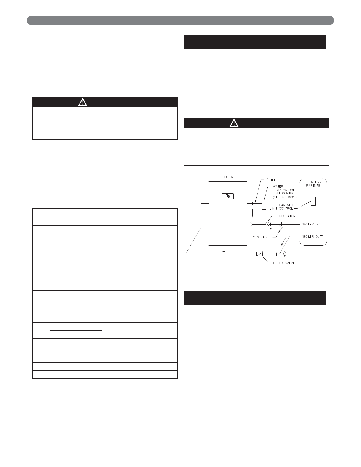
2. Install Boiler Water Temperature Limit Control in 1"
Tee on supply connection (same side of boiler as low
water cut-off). Set Limit at 160°F to avoid steam
generation during periods when only the domestic
water is calling for heat.
3. Install circulator and strainer in supply piping. Install
check valve to prevent gravity circulation.
E. STEAM BOILER PIPING - MULTIPLE
BOILERS
Refer to the PB Heat Steam Installation Survey and
Hydronics Institute Residential Hydronic Heating
Installation Design Guide for guidance on multiple boiler
installations.
Table 4.1: Steam Supply and Header Pipe Sizing
Always locate the steam supply take-off of the main
header between the equalizer and the last boiler
supply riser. Locating the steam supply between the
risers will cause a bullhead tee and cause water
carryover into the system.
NOTICE
Boiler
Model
Number of
Supply
Connections
Supply
Size (NPS)
Header
Size (NPS)
Equalizer
Size (NPS)
Evaporation
Rate (GPM)
63-03L 1 2 2 1-1/4 0.11
63-03 1 2 2 1-1/4 0.15
63-04L
1 2-1/2
2-1/2 1-1/4 0.19
2* 2*
63-04
1 2-1/2
2-1/2 1-1/4 0.23
2* 2*
63-05L
1 3
3 1-1/4 0.27
2* 2*
63-05
1 3
3 1-1/4 0.31
2* 2*
63-06
1 3
3 1-1/4 0.37
2* 2-1/2*
64-07
1 3
3 1-1/2 0.45
2* 2-1/2*
64-08 2 2-1/2 4 1-1/2 0.52
64-09 2 3 4 1-1/2 0.60
64-10 2 3 4 1-1/2 0.67
64-11 2 3 4 1-1/2 0.75
64-12 2 3 5 1-1/2 0.82
Maintain water level near normal water line to avoid
steam generation during periods when only the
domestic water is calling for heat.
Tank performance reduced when supplied by steam
boiler.
NOTICE
Figure 4.5: Typical Steam Boiler Indirect
Water Heater Piping
*Dual supplies may be used in lieu of larger single supply on
63-04L through 64-07 as indicated.
Page 18
16
FUEL PIPING
A. INSTALLATION
1. Pipe gas to the boiler in accordance with local codes.
In the absence of local regulations refer to the
National Fuel Gas Code, ANSI Z223.1/NFPA 54.
2. Size and install the gas supply piping to provide a
supply of gas sufficient to meet the maximum demand
of all appliances without excessive pressure drop.
3. The rate of gas to be provided to the boiler can be
determined by:
Obtain the gas heating value of the gas from the gas
supplier. As an alternative use Table 5.1.
4. Table 5.2 shows the maximum flow capacity of
several pipe sizes based on 0.3 inches of water
pressure drop. These values are based on a specific
gravity of 0.60. Apply the factors indicated in Table
5.3 for gas with specific gravity other than 0.60 to
obtain corrected capacities.
B. OPERATION
1. Assure that the gas supply pressure to the boiler is
regulated to 1/2 psi or less (approx. 13.5 inches of
water).
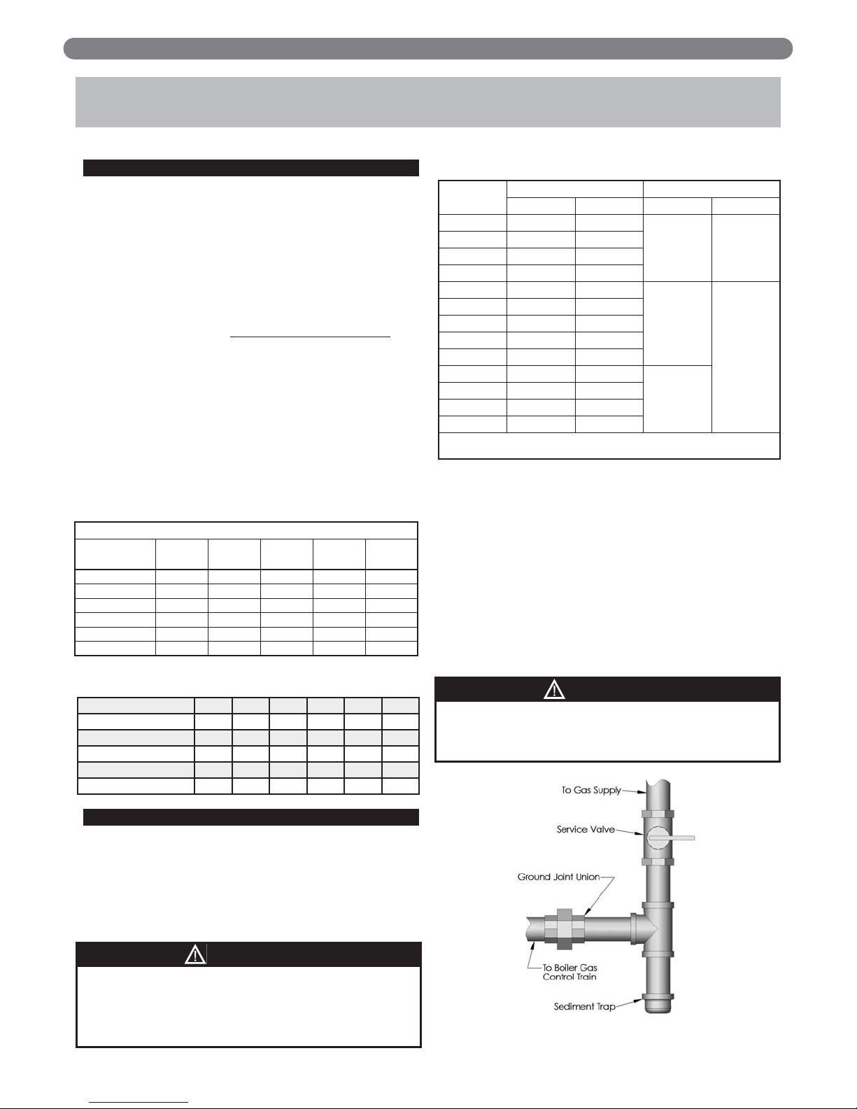
2. Install a service valve, sediment trap, and ground
joint union at the gas supply connection as shown in
Figure 5.1.
3. Check piping for leaks. Use an approved gas
detector or a non-corrosive leak detection fluid. If
leaks are found, turn off all gas supply to the
appliance and repair as necessary.
4. The boiler and its individual shut off valve must be
disconnected from the gas supply piping system
during any pressure testing of that system at test
pressures in excess of 1/2 psi (3.5kPa).
The boiler must be isolated from the gas supply
piping system by closing its individual manual shut
off valve during any pressure testing of the gas
supply piping system at test pressures equal to or less
than 1/2 psi (3.5 kPa).
5. FUEL PIPING
Based on Specific Gravity of 0.60
Pipe Length
(Feet)
1/2"
Pipe
3/4"
Pipe
1"
Pipe
1-1/4"
Pipe
1-1/2"
Pipe
10 132 278 520 1,050 1,600
20 92 190 350 730 1,100
30 73 152 285 590 890
40 63 130 245 500 760
50 56 115 215 440 670
60 50 105 195 400 610
Table 5.2: Maximum Capacity of Pipe in CFH for a
Pressure Drop of 0.3" of Water
Table 5.3: Maximum Capacity Correction Factors
Specific Gravity other than 0.60
Table 5.1: Gas Input & Valve Inlet
Do not subject the boiler gas valve to pressure in
excess of 1/2 psi (3.5 kPa). Doing so may damage the
valve.
CAUTION
Figure 5.1
Specific Gravity 0.50 0.55 0.60 0.65 0.70 0.75
Correction Factor 1.10 1.04 1.00 0.96 0.93 0.90
Specific Gravity 0.80 0.85 0.90 1.00 1.10 1.20
Correction Factor 0.87 0.84 0.82 0.78 0.74 0.71
Specific Gravity 1.30 1.40 1.50 1.60 1.70 1.80
Correction Factor 0.68 0.66 0.63 0.61 0.59 0.58
Use a pipe joint sealing compound that is resistant to
the action of liquefied petroleum gas. A non-resistant
compound may lose sealing ability in the presence of
this gas, resulting in a gas leak and fire or explosion
potential.
CAUTION
Boiler Input (BTU/HR)
CFH =
Gas Heating Value (BTU/FT³)
Model
Gas Input1(CFH) Gas Valve Inlet2(NPT)
Nat. Gas LP Gas Nat. Gat LP Gas
63-03L 88.5 35.4
1/2" 1/2"
63-03 118.0 47.2
63-04L 147.5 59.0
63-04 177.0 70.8
63-05L 206.5 82.6
3/4"
3/4"
63-05 236.0 94.4
63-06 287.5 115.0
64-07 345.0 138.0
64-08 399.0 159.6
64-09 460.0 184.0
1"
64-10 517.5 207.0
64-11 575.0 230.0
64-12 632.5 253.0
1. Natural Gas Based on 1000 Btu./Cubic Foot, LP Gas Based on 2500 Btu./Cubic Foot.
2. See instructions for sizing gas supply piping.
Page 19
17
FUEL PIPING
5. Refer to table 5.4 for minimum supply pressure for
the purpose of input adjustment.
6. Install the boiler such that the gas ignition system
components are protected from water (dripping,
spraying, rain, etc.) during appliance operation and
service (circulator replacement, condensate trap
clean out, control replacement, etc.)
7. The boiler and its gas connection must be leak tested
before placing the boiler in operation.
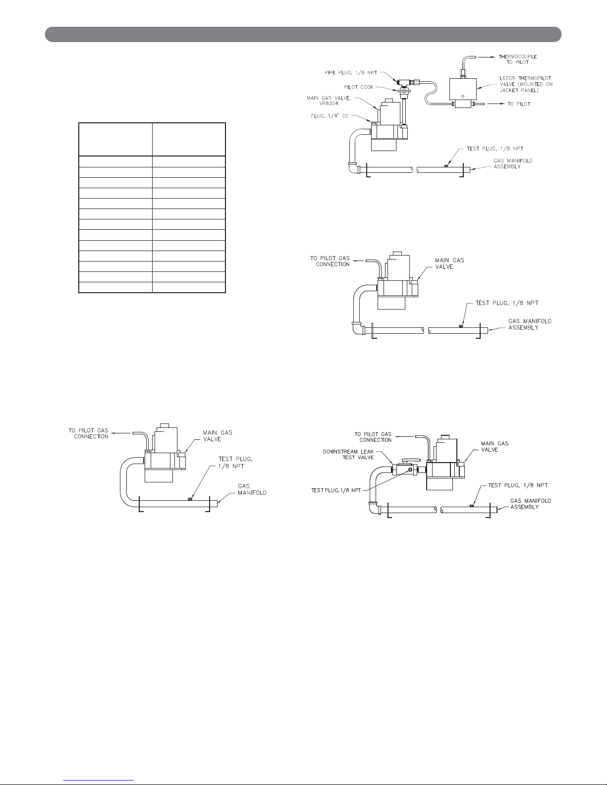
8. Typical gas train manifolds are illustrated in Figure
5.2 through 5.5.
Model
Supply
Pressure
(in. Water)
63-03L 5.00
63-03 5.00
63-04L 5.00
63-04 5.35
63-05L 5.00
63-05 5.00
63-06 5.56
64-07 5.00
64-08 5.27
64-09 5.00
64-10 5.00
64-11 5.00
64-12 5.10
Table 5.4: Minimum Supply
Pressure Natural Gas
Figure 5.2: Gas Train Manifold 63-03L
Through 63-06
Figure 5.5: Gas Train Manifold – Natural & LP Gas
64-09 Through 64-12
Figure 5.4: Gas Train Manifold – 64-07/08 LP Gas,
Standing Pilot & 64-07/08 Spark
Ignited Natural & LP Gas
Figure 5.3: Gas Train Manifold – 64-07 & 64-08
Natural Gas, Standing Pilot
Page 20
18
CONTROLS & TRIM
A. WATER BOILER CONTROLS & TRIM
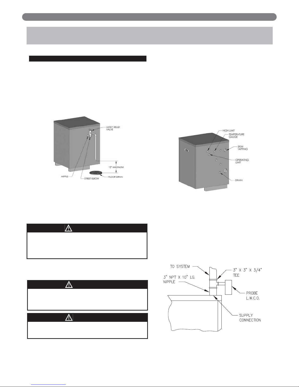
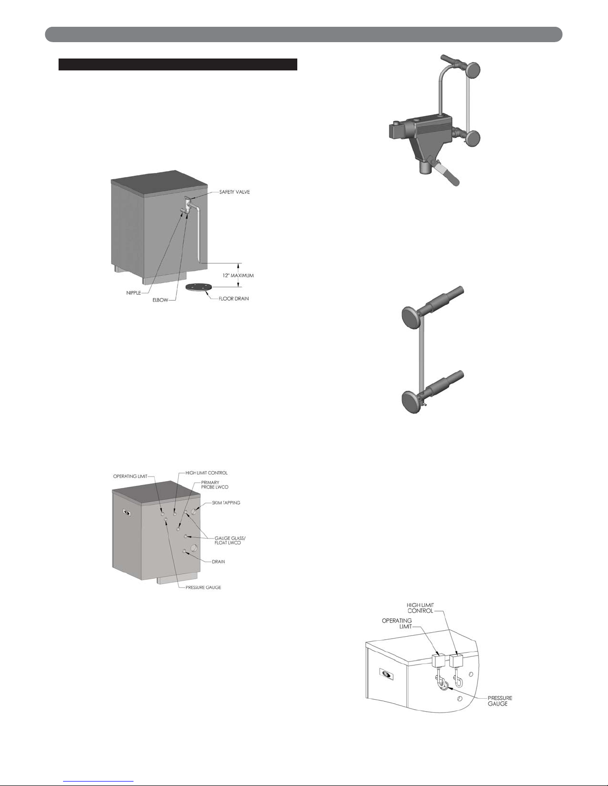
1. Safety Relief Valve:
a. Pipe the boiler relief valve into the 3/4" tapping
on the left side of the boiler as shown in Figure
6.1. Be sure that the relief valve is sized in
accordance with local code requirements. In
addition, be sure that the relief valve is designed
constructed and stamped in accordance with
ASME Boiler and Pressure Vessel Code,
Section IV.
b. If it is necessary to use a boiler relief valve larger
than 3/4" due to local codes, the relief valve
should be piped in the boiler skim tapping. Do
not increase the size between the boiler
and the valve.
c. Pipe the discharge of the safety relief valve to a
maximum of 12" from the floor. Pipe the relief
outlet close to a floor drain.
2. Drain Valve:
Install the 3/4" drain valve provided into the drain
tapping on the right hand side of the boiler. Refer to
Figure 6.2 for tapping location.
3. Pressure/Temperature Gauge:
Install the pressure/temperature gauge (theraltimeter)
supplied with the boiler into the 1/2" tapping located
on the right side of the boiler. Refer to Figure 6.2 for
tapping location.
4. Limit Control(s):
a. Install the operating limit control provided in the
3/4" tapping located on the right side of the
boiler. Refer to Figure 6.2 for tapping location.
b. (64-09 through 64-12) Install a high limit control
in the 3/4" tapping located above the operating
limit control. Refer to Figure 6.2 for location.
5. Low Water Cut-off (Level Control)
a. A hot water boiler installed above radiator level
or as required by the authority having jurisdiction
must be provided with a low water cut-off device
either as part of the boiler or at the time of
installation.
b. If a probe-type low water cut-off is used it should
be piped into the boiler supply piping as shown
in Figure 6.3.
6. CONTROLS & TRIM
Do not install any valves or restrictions between the
relief valve and the boiler. Be sure that the inlet to the
relief valve is the same or smaller pipe size than the
boiler connection.
CAUTION
Pipe the discharge of the relief valve away from any
traffic area. Failure to do this may cause injury if the
valve discharges.
CAUTION
Pipe the discharge of the relief valve using the full
size of the discharge connection.
CAUTION
Figure 6.2 Water Boiler Tapping Locations
Figure 6.1 Relief Valve Piping Water Boiler
Figure 6.3 Probe Low Water Cut-off Piping
Page 21
19
CONTROLS & TRIM
B. STEAM BOILER CONTROLS & TRIM
1. Safety Valve:
a. Pipe the boiler safety valve provided into the 3/4"
tapping on the left side of the boiler as shown in
Figure 6.4. Be sure that the relief valve is sized in
accordance with local code requirements. In
addition, be sure that the safety valve is designed
constructed and stamped in accordance with the
ASME Boiler and Pressure Vessel Code, Section IV.
b. If it is necessary to use a boiler relief valve larger
than 3/4" due to local codes, the relief valve
should be piped in the boiler skim tapping. Do
not increase the pipe size between the
boiler and the valve.
c. Pipe the discharge of the safety valve to a
maximum of 12" from the floor. Pipe the outlet
close to a floor drain.
2. Drain Valve:
Install the 3/4" drain valve provided into the drain
tapping on the right hand side of the boiler. Refer to
Figure 6.5 for tapping location.
3. Low Water Cut-off (Level Control):
a. Float Type: Install the float type low water cut-
off (if provided) in conjunction with the gauge
glass as shown in Figure 6.6.
b. Probe Type: Install the optional probe type low
water cut-off into the 3/4" tapping on the right
side of the boiler. Refer to Figure 6.5 for tapping
location. The supplied control incorporates a 60
second off cycle after a 15 minute on cycle. This
feature allows the water level in the boiler to settle
so that the probe can sense a true water level.
4. Gauge Glass:
a. Install the gauge glass provided into two 1/2"
tappings on the right side of the boiler. If a float
type low water cut-off is used, it will be piped
into these same fittings. See Figure 6.6 and 6.7
for examples of this installation.
5. Pressure Gauge:
a. Install the operating limit control and pressure
gauge in the 3/4" tappings located on the right
side of the boiler. Refer to Figure 6.5 for tapping
location.
6. Limit Control(s): (Figure 6.8)
a. Install the operating limit control and pressure
gauge in the 3/4" tappings located on the right
side of the boiler. Refer to Figure 6.5 for tapping
locations.
b. (64-09 through 64-12) Install a high limit control
in the 3/4" tappings located to the right of the
operating limit control. Refer to Figure 6.5 for
location.
Figure 6.6: Gauge Glass & Low Water Cut-Off
Installation
Figure 6.5: Steam Boiler Tapping Location
Figure 6.7: Gauge Glass Installation
Figure 6.8: Limit Control Installation
Figure 6.4
Page 22
20
ELECTRICAL
A. CONNECT SUPPLY WIRING
1. All electrical wiring must be done in accordance with
local codes. In the absence of local codes use
ANSI/NFPA 70 “The National Electrical Code.”
2. The boiler must be electrically bonded to ground in
accordance with the requirements of the authority
having jurisdiction or, in the absence of such
requirements, with the National Electrical Code,
ANSI/NFPA 70 and/or the Canadian Electrical Code
Part 1, CSA C22.1, Electrical Code.
3. The boiler is to be connected to a separate,
permanently live electrical supply line with a fused
disconnect switch.
B. MOUNT REMAINING CONTROLS
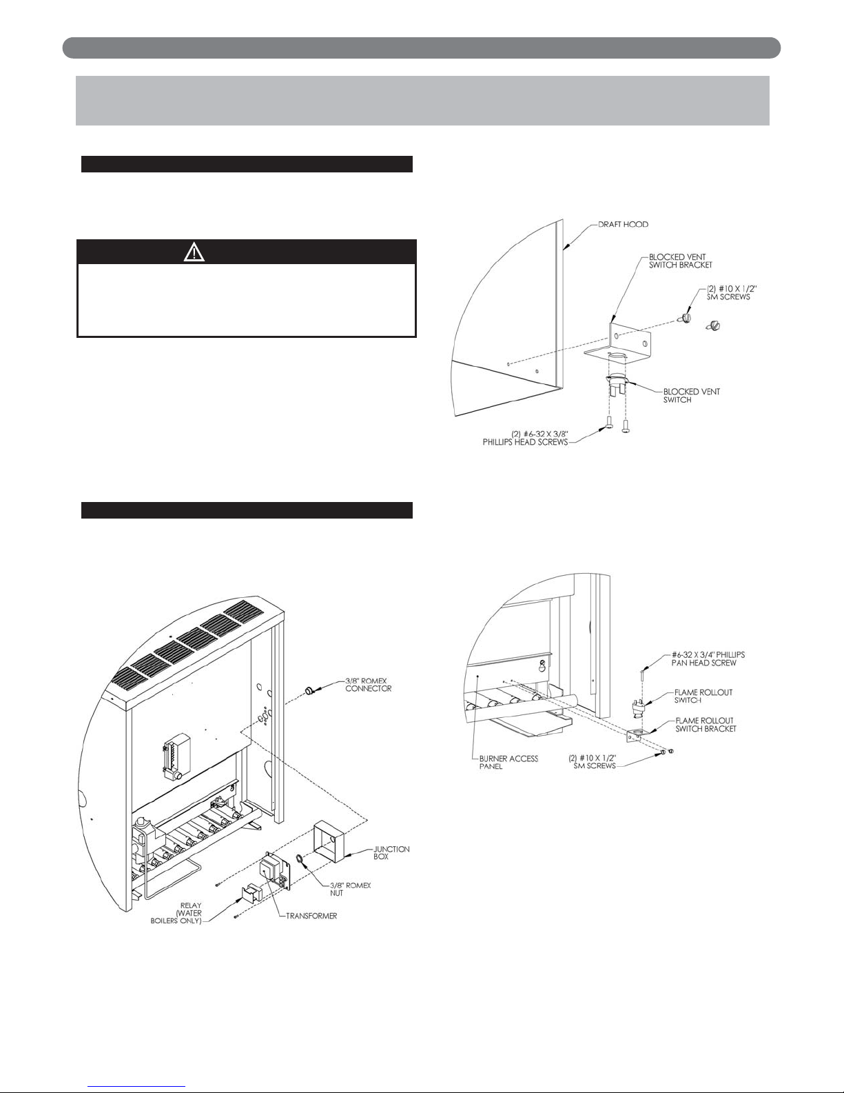
1. Mount the control transformer on the junction box as
shown in Figure 7.1.
2. Mount the blocked vent switch in the rear of the
boiler on the draft hood as shown in Figure 7.2.
3. Mount the flame rollout switch as shown in Figure 7.3.
7. ELECTRICAL
Label all wires prior to disconnection when servicing
controls. Wiring errors can cause improper and
dangerous operation. Verify proper operation after
servicing.
CAUTION
Figure 7.1
Figure 7.2
Figure 7.3
Page 23
21
ELECTRICAL
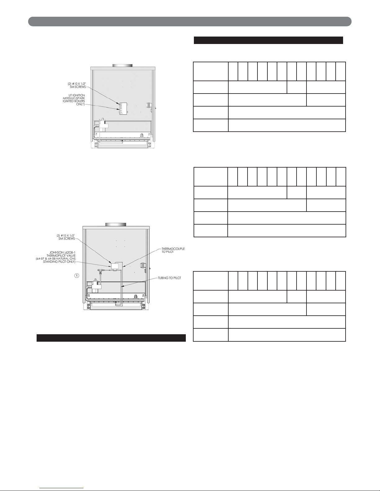
4. Mount the ignition module, if required (spark ignited
units only), as shown in Figure 7.4.
5. Mount the thermopilot valve (Johnson L62), if
required (standing pilot only on 64-07 & 64-08
Natural Gas), as shown in Figure 7.5.
C. INSTALL CONTROL WIRING
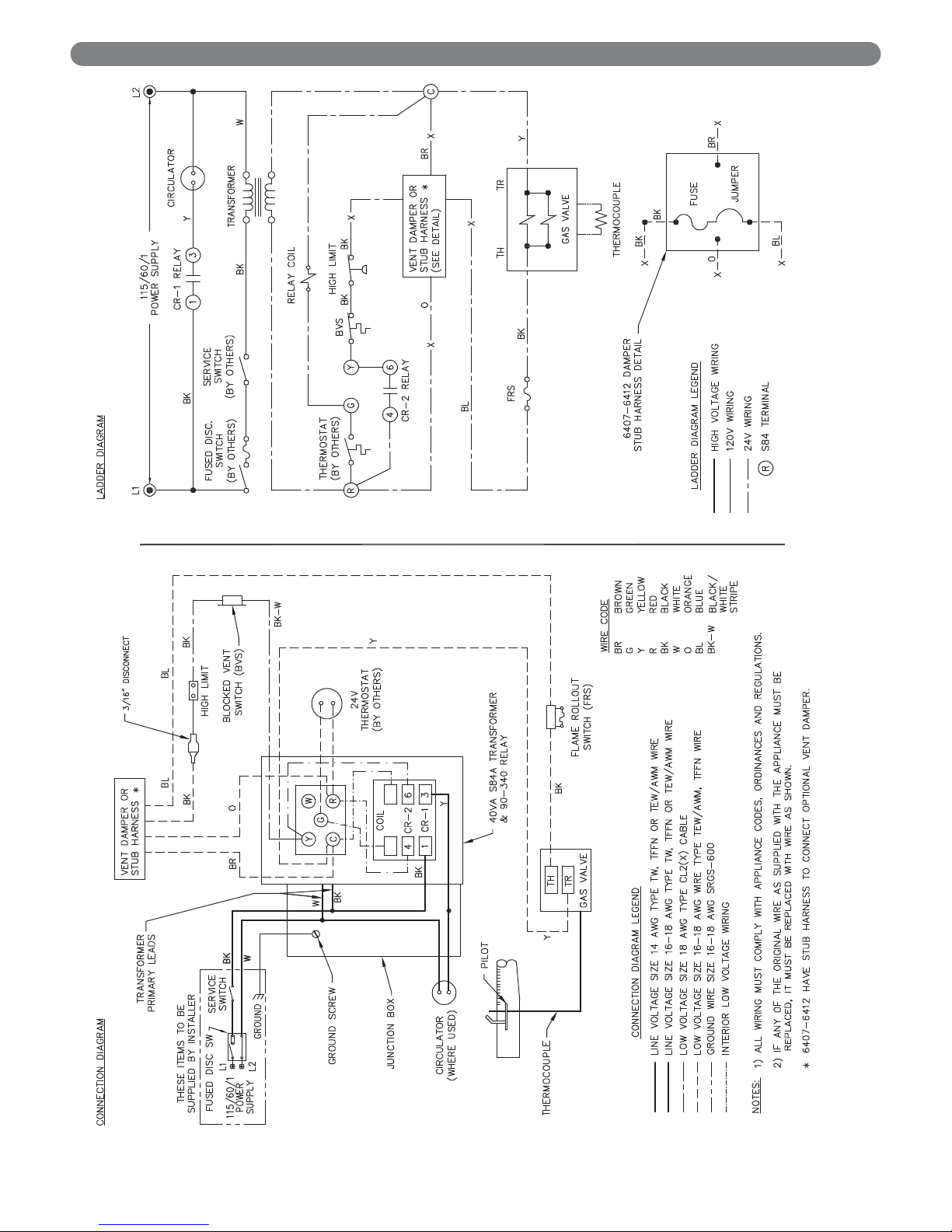
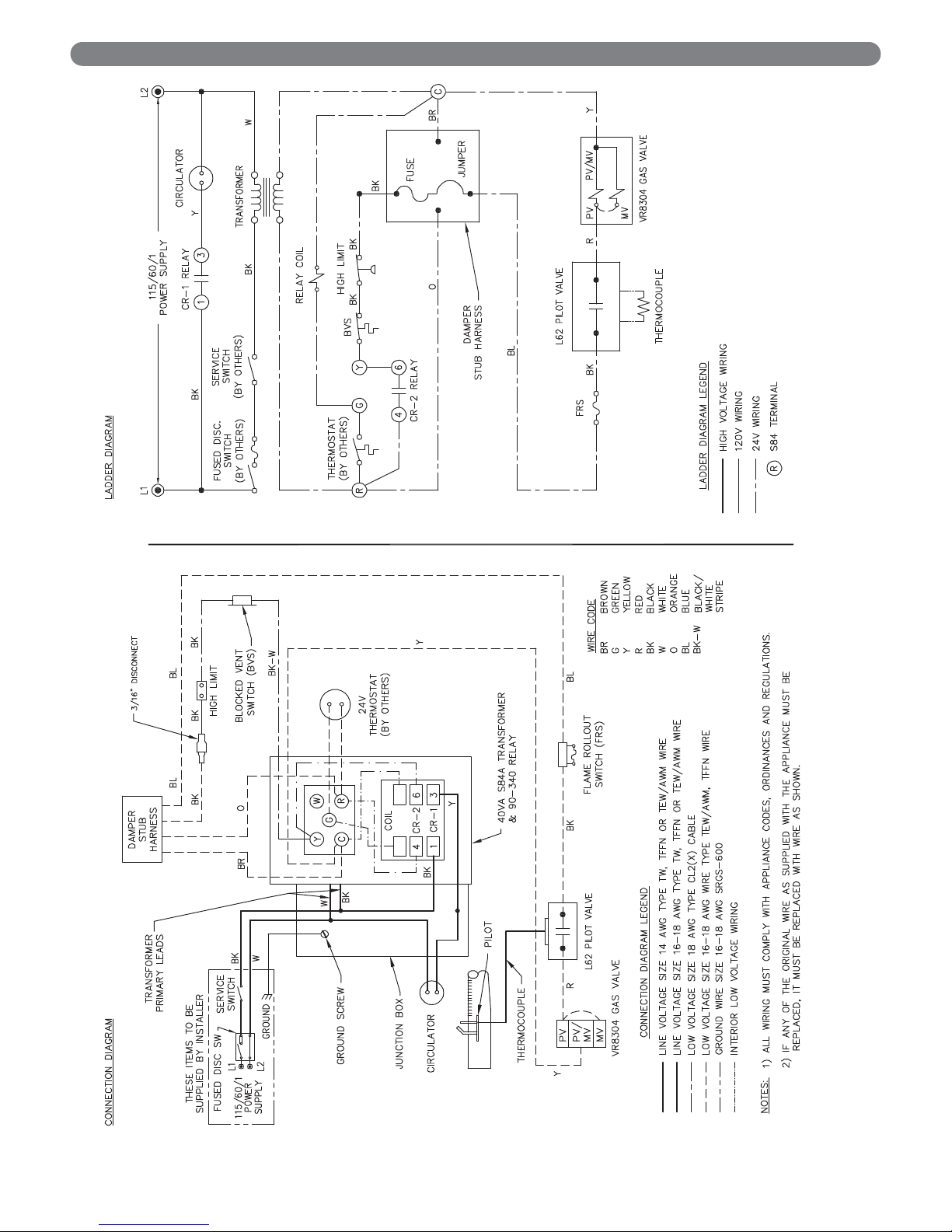
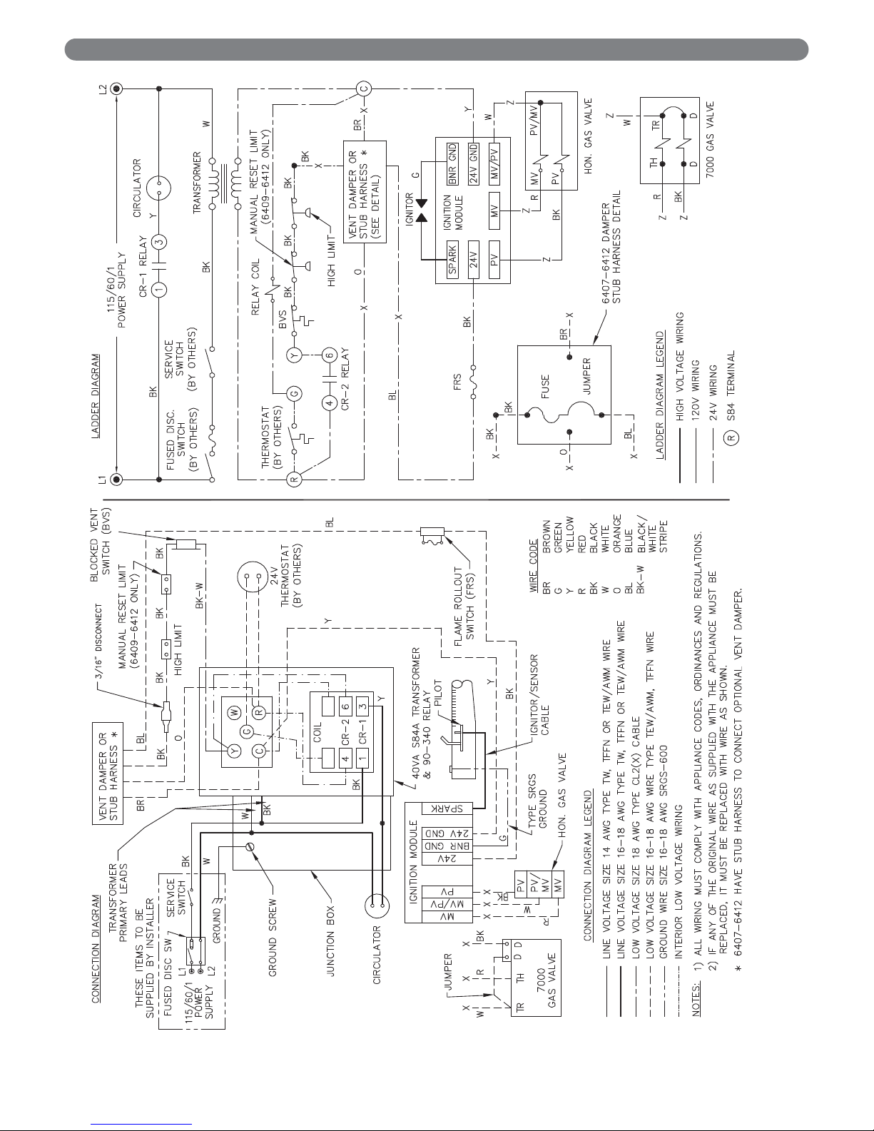
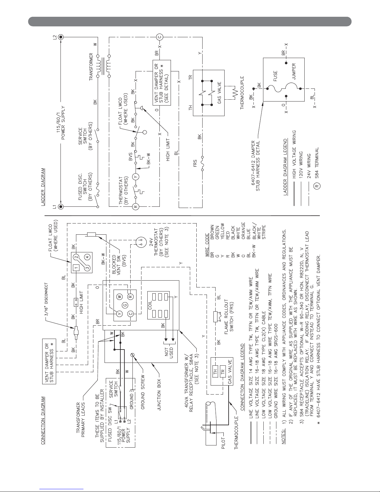
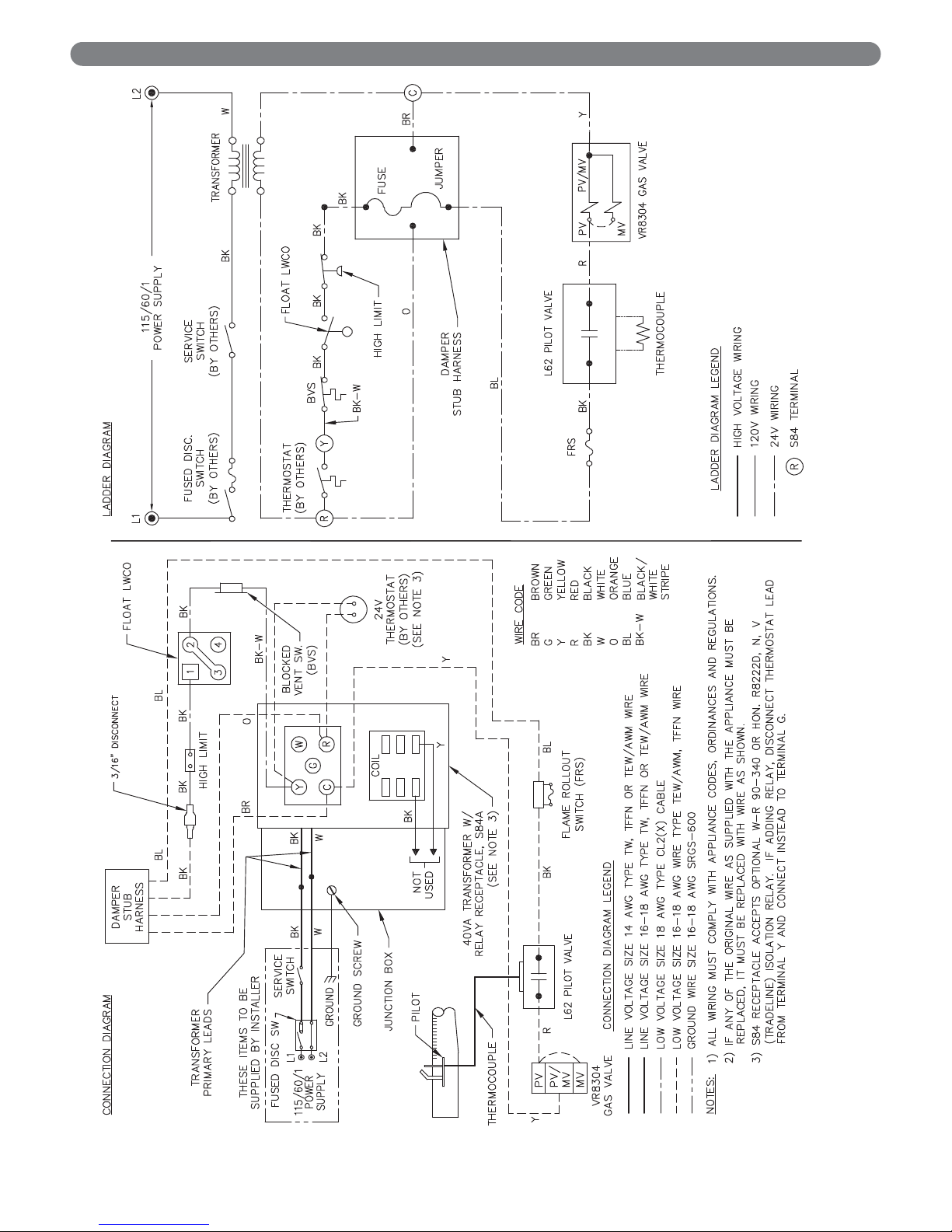
1. Wire the boiler according to the wiring diagram
supplied with the boiler (in the Control Envelope).
Figures 7.6 to 7.15 are provided for reference only.
2. Install all line voltage wiring in approved electrical
conduit.
3. Do not install single pole switches, including safety
controls, in the neutral leg.
D. WIRING DIAGRAM INDEX
Figure 7.4
Figure 7.5
63-03L
63-03
63-04L
63-04
63-05L
63-06
64-07
64-08
64-09
64-10
64-11
64-12
Standing Pilot,
Natural Gas
Fig. 7.6 Fig. 7.7 N/A
Standing Pilot,
LP Gas
Fig. 7.6 N/A
Spark Ignition,
Natural Gas
Fig 7.8
Spark Ignition,
LP Gas
Fig. 7.8
63-03L
63-03
63-04L
63-04
63-05L
63-06
64-07
64-08
64-09
64-10
64-11
64-12
Standing Pilot,
Natural Gas
Fig. 7.9
Fig.
7.10
N/A
Standing Pilot,
LP Gas
Fig. 7.9 N/A
Spark Ignition,
Natural Gas
Fig 7.11
Spark Ignition,
LP Gas
Fig. 7.11
63-03L
63-03
63-04L
63-04
63-05L
63-06
64-07
64-08
64-09
64-10
64-11
64-12
Standing Pilot,
Natural Gas
Fig. 7.12
Fig.
7.13
N/A
Standing Pilot,
LP Gas
Fig. 7.12 N/A
Spark Ignition,
Natural Gas
Fig 7.14
Spark Ignition,
LP Gas
Fig. 7.14
Table 7.1: Wiring Diagram Index - Water Boilers
Table 7.2: Wiring Diagram Index - Steam Boilers
w/Float LWCO
Table 7.3: Wiring Diagram Index - Steam Boilers
w/Probe LWCO
Page 24
22
ELECTRICAL
Figure 7.6: Water Boiler with Standing Pilot. Wiring Diagram for Series 63™ and for Models 64-07 and 64-08 with LP Gas Fuel.
Page 25
23
ELECTRICAL
Figure 7.7: Water Boiler with Standing Pilot. Wiring Diagram for 64-07 and 64-08 with Natural Gas Fuel.
Page 26
24
ELECTRICAL
Figure 7.8: Water Boiler with Spark Ignition. Wiring Diagram for all Models.
Page 27
25
ELECTRICAL
Figure 7.9: Steam Boiler with Float Low Water Cut-off only and Standing Pilot Wiring Diagram for Series 63™ and 64-07 and 64-08 with
LP Gas Fuel
Page 28
26
ELECTRICAL
Figure 7.10: Steam Boilers with Float Low Water Cut-off only and Standing Pilot. Wiring Diagram for Models 64-07 and 64-08 Natural Gas Only.
Page 29
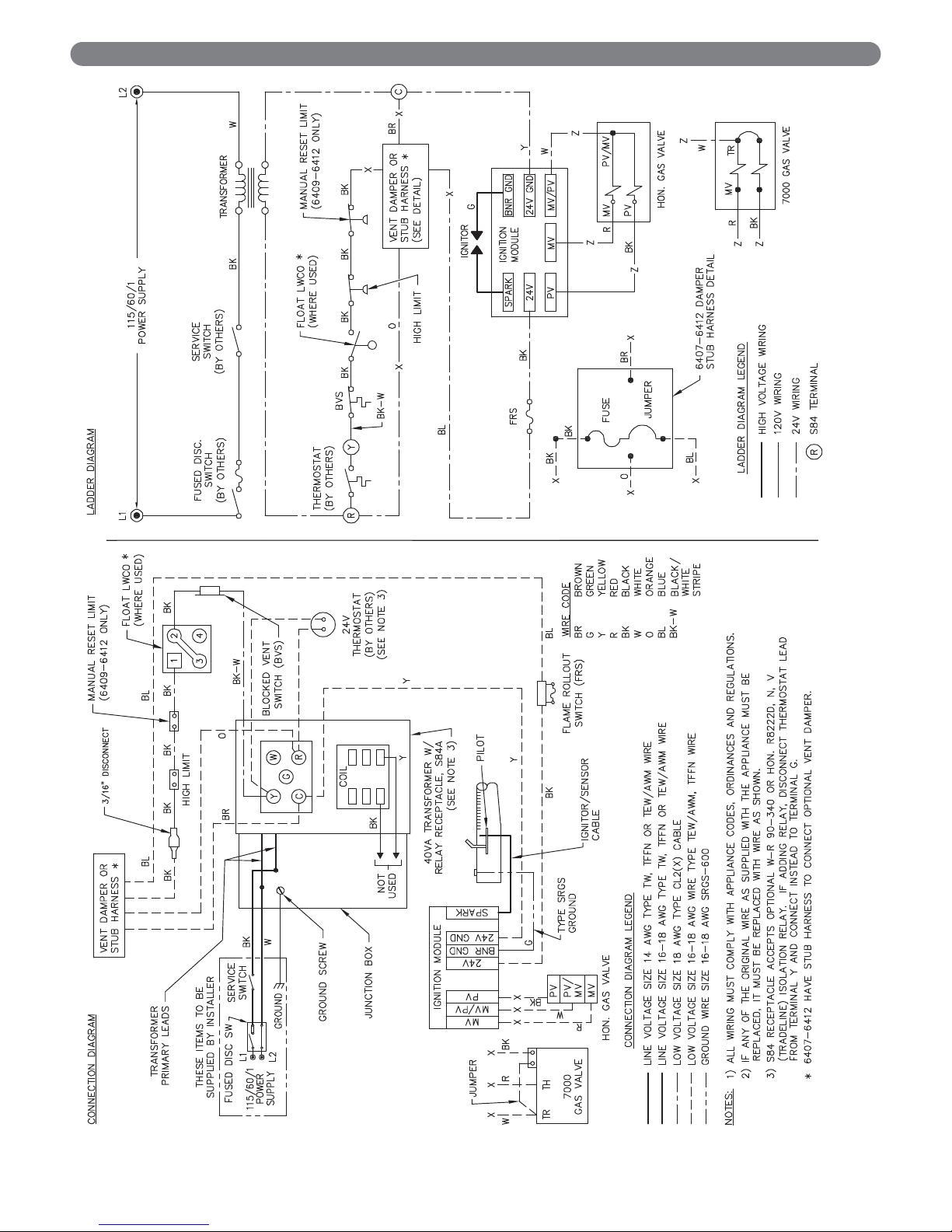
27
ELECTRICAL
Figure 7.11: Steam Boiler with Spark Ignition. Wiring Diagram for Models with Float Low Water Cut-off.
Page 30
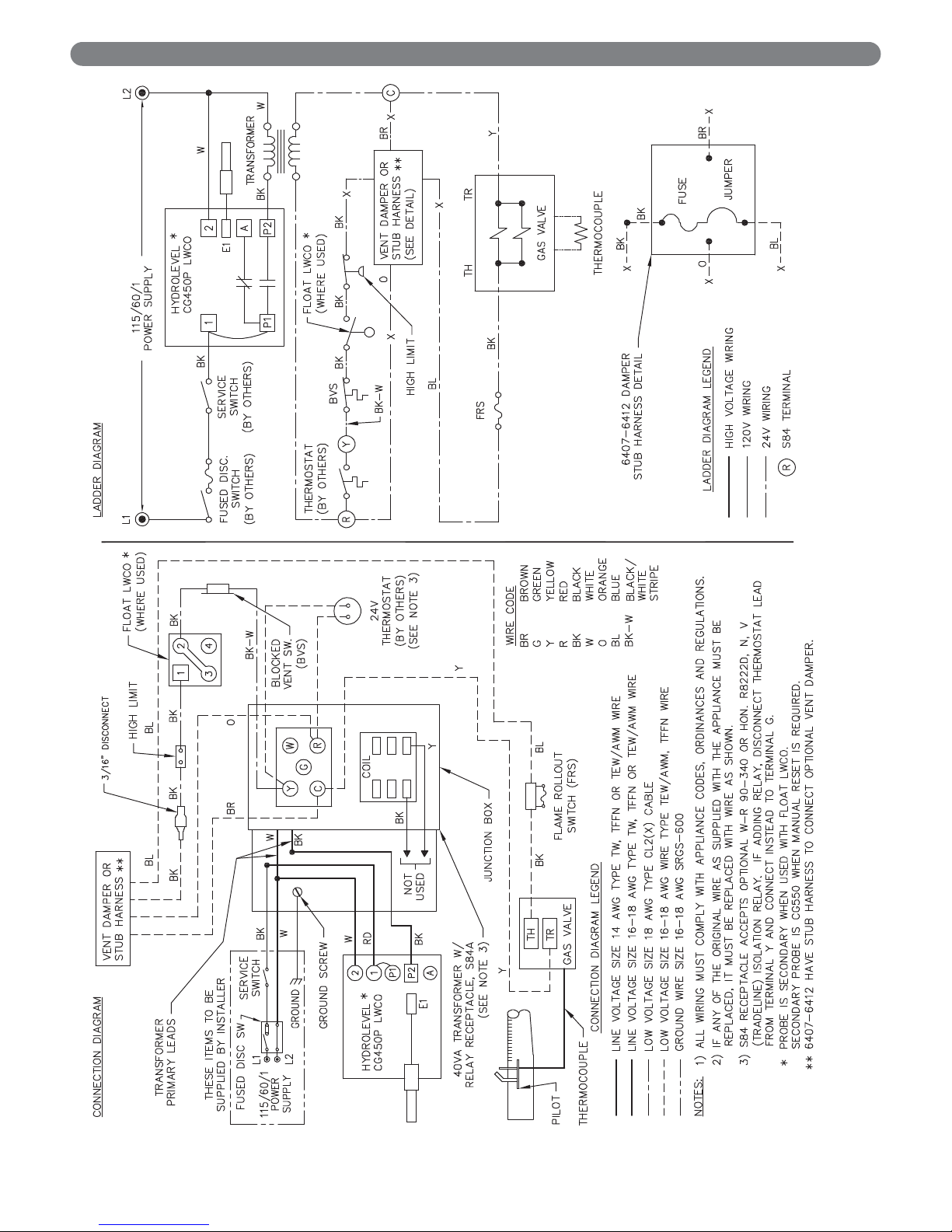
28
ELECTRICAL
Figure 7.12: Steam Boilers with Probe Low Water Cut-off and Standing Pilot Wiring Diagram for Series 63™ and Models 64-07 and 64-08 LP
Gas Only.
Page 31
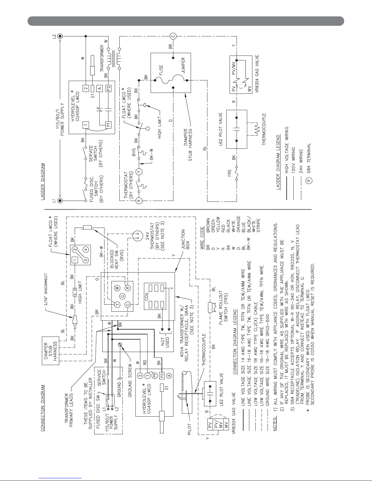
29
ELECTRICAL
Figure 7.13: Steam Boilers with Probe Low Water Cut-off and Standing Pilot. Wiring Diagram for Models 64-07 and 64-08 Natural Gas.
Page 32
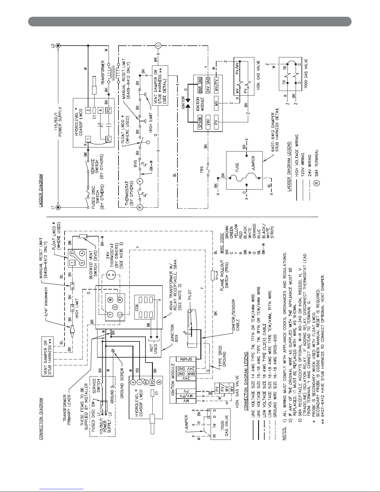
30
ELECTRICAL
Figure 7.14: Steam Boiler with Spark Ignition. Wiring Diagram for Models with Probe Low Water Cut-off.
Page 33
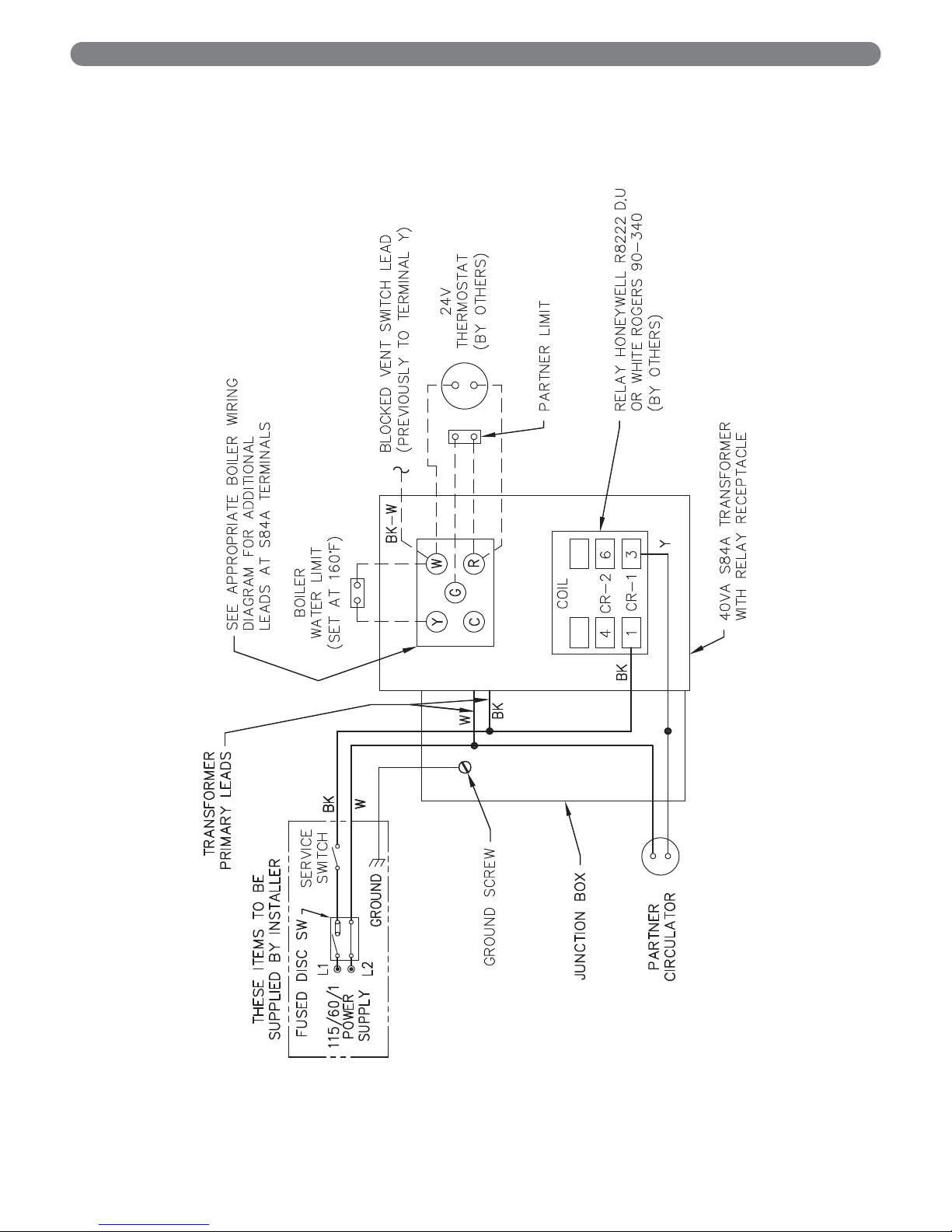
31
ELECTRICAL
Figure 7.15: Typical Steam Boiler Indirect Water Heater Wiring
Page 34
32
BOILER OPERATION
8. BOILER OPERATION
A. SYSTEM INSPECTION
1. Confirm that all water, gas, and electricity are
turned off.
2. Inspect the boiler combustion chamber for
obstructions. Clear any debris from the combustion
chamber.
3. Check the condition of the burners and pilot
assembly. Make certain that there are no unusual
bends. Replace components if necessary.
4. Verify that water piping, gas piping and electrical
wiring are installed properly. Be sure that all
components are installed correctly. Refer to these
instructions as well as to component manufacturer’s
instructions.
B1. FILL THE BOILER (WATER BOILERS)
1. Fill the boiler and system with water making certain
to vent air from all high points in the system. Water
should bleed from each air vent when it is opened.
2. The pressure reducing valve on the fill line will
typically allow the system to be filled and pressurized
to 12 psi. Consult the valve and expansion tank
manufacturer for more detailed information.
3. Check all joints and fittings throughout the system for
leaks. If leaks are found, drain the system and repair
as required.
4. If the water hardness is high, use water treatment to
reduce the deposition of minerals in the boiler.
5. If the system requires antifreeze protection, use only
propylene glycol specially formulated for hydronic
systems. These contain inhibitors that prevent
corrosion of the boiler and system components. Do
not use ethylene glycol or automotive antifreezes.
a. Make sure that the antifreeze supplier can
provide periodic testing of antifreeze
concentration and inhibitor level.
b. If an automatic fill valve is used, the solution
strength in the system must be checked to assure
that the antifreeze concentration has not been
overly diluted.
c. Local codes may require the addition of a
backflow preventer or manual fill only with
separation from the city water supply.
d. Consider the minimum temperature of potential
exposure in the system when deciding on the
antifreeze concentration. A concentration of
50% generally provides protection from freezing
to -30°F.
B2. FILL THE BOILER (STEAM BOILERS)
1. Gravity Systems and Pumped Return with
Condensate Units – Fill the boiler to the normal
water line as indicated on the boiler jacket. The
normal water level is about 25-7/8" above the boiler
foundation (about 2/3 of the gauge glass).
2. Pumped Return Systems with Boiler Feed Unit Fill the boiler using the boiler feed unit. The fill level
will depend on the control being used but should be
roughly 25-7/8" above the boiler foundation (about
2/3 of the gauge glass) when the feed pump stops.
3. Check all joints and fittings in system piping below
the water line for leaks and repair as necessary.
C. STUDY LIGHTING INSTRUCTIONS
Before starting the boiler, study the Lighting Instructions
supplied with the boiler. Figure 8.2 to 8.5 show typical
Lighting Instructions for typical boilers.
See Table 8.1 to determine the correct figure.
D. RUN PILOT CHECK-OUT
1. Shut off all electrical power to the boiler.
2. Close Main and Pilot gas shut-off valves. Wait for
five (5) minutes.
3. Set the Operating and Limit Temperature Controls to
minimum setting so they will not call for heat.
4. Perform Pilot Check:
a. Turn main electric disconnect switch to the “ON”
position.
b. Turn up the settings on the Operating and Limit
Temperature Controls so they will call for heat.
c. Check for a continuous spark at the electronic
spark-ignited pilot.
d. Spark-ignited pilot systems – The control will
spark for 90 seconds (trial for ignition), then shut
down for a 5 to 6 minute wait period before
attempting another ignition.
e. Standing pilot systems – Within 180 seconds the
control will click, indicating a safety lockout.
f. Turn down the Operating Temperature Control to
stop the call for heat.
g. Wait 60 seconds to allow the control to reset
before proceeding with the next step.
5. Light Manual Pilot
a. Follow the procedure in the Lighting Instructions
to manually light any standing pilots.
63-03L
63-03
63-04L
63-04
63-05L
63-06
64-07
64-08
64-09
64-10
64-11
64-12
Standing Pilot, Nat. Gas Fig. 8.2 Fig.8.3
N/A
Standing Pilot, LP Gas Fig. 8.2
Spark Ignition, Nat. Gas Fig 8.4 Fig. 8.5
Spark Ignition, LP Gas Fig. 8.4
Table 8.1: Lighting & Operating Instructions
Figure Selection Chart
Page 35

33
BOILER OPERATION
6. Spark-Ignited Pilot Ignition Check
a. Turn up the Operating Temperature Control for a
call for heat.
b. The spark-ignited pilot should ignite.
c. Turn down the Operating Temperature Control to
stop the call for heat.
d. The spark-ignited pilot should shut off.
7. Check Main Burner Ignition
a. With the Operating Temperature Control turned
down, open the main gas shut-off valve(s).
b. Turn up the Operating Temperature Control for a
call for heat.
c. The electronic spark-ignited pilot(s) should ignite.
d. The main gas valves will then open and the main
burners should ignite.
e. Turn down the Operating Temperature Control to
stop the call for heat.
f. The electronic spark-ignited pilot(s) and main
burners should shut off.
E. CHECK MAIN BURNER SYSTEM
1. Remove the pressure test plug at the Main gas shut-
off valve. Attach a U-tube manometer.
2. Restart the boiler by turning up the Operating
Temperature Control for a call for heat.
3. Leak test all gas train joints with a soap suds
solution.
4. Check the gas pressure at the entrance to the Gas
Control train.
a. The pressure reading under flow should be
between 5.5 and 13.5 inches water column
b. If the pressure to the Gas Control Train exceeds
13.5 inches under any conditions, the system must
be provided with a lockup type gas pressure
regulator to provide 13.5 inches maximum.
5. Check the Manifold gas pressure.
a. Remove the 1/8" pipe plug from the manifold gas
pressure tapping.
b. Attach a U-tube manometer.
c. Adjust the Main Gas Pressure Regulator to obtain
3.5 inches water column on Natural Gas or 10
inches water column on Propane (LP) Gas.
d. NOTE: If the pressure is adjusted to set the
nameplate input to the boiler, do not set it more
than 0.3 inches plus or minus from the specified
settings. If more adjustment to the rate is needed, it
must be done by changing the burner gas orifices.
6. Check the burner input by reading the gas meter.
a. The required input rate is listed for each model in
Section II, Dimensions & Ratings.
b. Determine the input by multiplying “F” – Meter
Reading (Cubic Feet of Gas) times “H” – Heating
Value of Gas (Btu per Cubic Foot) times 3600.
Divide by “T” – the time in seconds at the meter
reading.
c. Note: If the meter is not automatically corrected
for temperature and pressure, the meter reading
must be corrected to actual conditions during the
rate test.
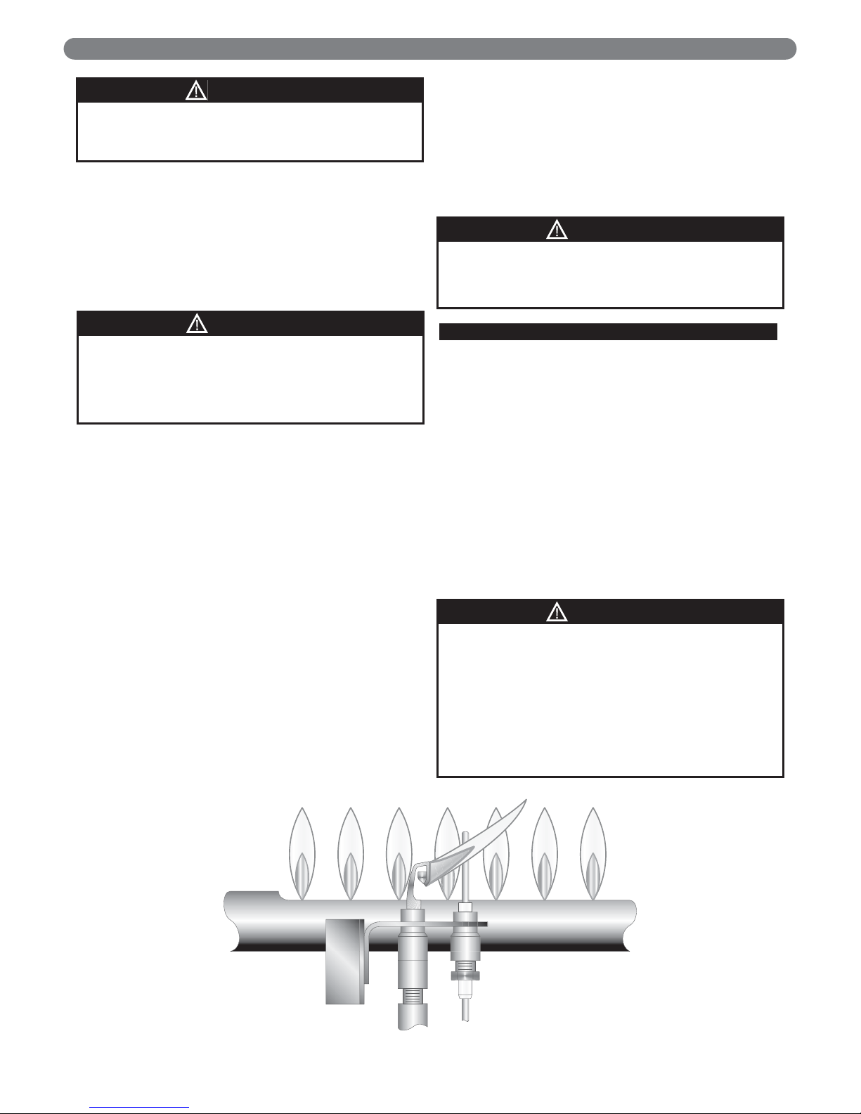
7. Check the burner and pilot flames (see Figure 8.1).
The flame inner cone should be about 1-1/2" high
and should have a very sharp blue color. Poor flame
conditions can be caused by dirty burners,
obstructed orifices or incorrect gas pressure.
F. CHECK BOILER CONTROLS
1. Limit and Operating Controls:
·
Lower the set point of each control until the
burners shut down. Note that the system pressure
(or temperature) corresponds to the limit setting.
·
Return the controls to the desired set point.
2. Low Water Cut-off (if used):
·
Consult the manufacturer’s instructions for the
low water cut-off operational check procedure.
3. Main Gas Safety Shut-off Valve:
·
Close main supply manual shut-off valve.
The main gas safety shut-off valve should
de-energize.
·
Open the manual supply valve. Re-light the
boiler in accordance with the lighting instructions.
G. PURGE AIR FROM THE SYSTEM
(WATER BOILERS ONLY)
1. Purge the system using purge valves, isolating zones
in the process or use system vents. Do not operate
the pump(s) while purging. Pumps will hold air in
the eye of the impeller.
2. Allow the system to reach 180°F and use manual
vents, if installed, to remove any remaining air.
H. CHECK THE SYSTEM PRESSURE
(WATER BOILERS ONLY)
Watch the pressure gauge as the system approaches
180°F. If the pressure exceeds the design operating
pressure, check:
a. Fill valve pressure.
b. Expansion or compression tank operation and sizing.
I. CLEAN THE BOILER
(STEAM BOILERS ONLY)
1. Clean the boiler as described below no later than
one week after the initial start-up. Cleaning will be
more effective if the boiler operates 24 to 48 hours
in order to loosen sediment and impurities in the
system.
2. The boiler must be cleaned to remove any
accumulation of oil, grease, sludge, or other
impurities that may be in the system. These
substances can cause foaming and surging of the
boiler water, producing an unstable water line and
water carryover to the system.
Rate, Btu/Hr =
F x H x 3600
T
Page 36
34
BOILER OPERATION
3. Thread a 1-1/4" NPT Pipe Nipple into the “Skim
Tapping” (Connection “J” in Figure 11.1). Tighten
firmly.
4. Thread a 1-1/4" NPT ball valve onto the nipple and
connect a 1-1/4" drain line.
5. Close all valves to the system. Provide a means of
supplying fresh water to the boiler.
6. Use common washing soda (such as Arm &
Hammer Super Washing Soda). For each 800 square
feet EDR net boiler rating, mix one pound of
washing soda with water. Pour mixture into safety
relief valve tapping.
7. Open the skim valve. Fill the boiler until water begins
to flow out of the valve.
8. Turn burners on and allow the boiler water to heat
up to between 180ºF and 200ºF. Cycle the burners
to maintain temperature during skimming. Do not
allow the boiler to steam. Steaming mixes up the
contaminants in the water instead of floating them at
the surface.
9. Open the make-up water valve to continuously feed
water to the boiler. Allow water to flow out of the
skim tapping.
10. Continue skimming the boiler until the water flowing
from the skim tapping flows clear. This will likely take
several hours for a dirty system.
11. After skimming is complete, close the skim valve and
turn off the boiler.
12. Close the make up water valve and open the boiler
drain valve.
13. Drain the boiler completely. Then refill and drain
again one or two times to make sure all of the soda
has been washed out.
14. Open the valves to the system and replace the skim
valve with a pipe cap.
J. TO SHUT DOWN THE BOILER
1. Open main line power disconnect switch to boiler.
2. Close Main and Pilot gas shut-off valves.
3. To take boiler out of service if the boiler and system
are not to be used when temperatures are below
freezing:
a. Drain the boiler and system completely and shut
off make-up water supply.
b. Open main line power disconnect switch to
boiler. Remove the fuses or secure the switch so
that the power cannot be turned on accidentally.
c. Be certain that the boiler and system are refilled
before returning to service. Follow the
Instructions in this manual and the Lighting
Instructions to operate.
Cleaning the boiler requires the use of very hot water
and corrosive chemicals. Use care when handling to
prevent injury.
WARNING
Do not leave the boiler unattended while performing
boil out. Do not allow the water to drop below the
bottom of the gauge glass or allow make up water to
enter too quickly. This will avoid the possibility of
causing failure of the boiler sections.
CAUTION
If the gauge glass becomes dirty again, this indicates
that more contaminants have worked loose in the
system. Repeat the cleaning and skimming process
as needed to clean the system.
NOTICE
Before servicing the boiler:
• Turn off all electrical power to the boiler.
• Close the Gas Service Valve.
• Allow the boiler to cool if it has been operating.
• Label all wires prior to disconnection when
servicing controls. Wiring errors can cause
improper and dangerous operation. Verify proper
operation after servicing.
CAUTION
Figure 8.1 Pilot and Burner Flames
Page 37
35
BOILER OPERATION
H24V VR8200/VR8300 9177R REV.3
If you cannot reach your gas supplier, call the fire
department.
C. Use only your hand to push in or turn the gas control
knob. Never use tools. If the knob will not push in or
turn by hand, don't try to repair it, call a qualified
service technician. Force or attempted repair may
result in a fire or explosion.
D. Do not use this appliance if any part has been under
water. Immediately call a qualified service technician
to inspect the appliance and to replace any part of the
control system and any gas control which has been
under water.
WARNING: If you do not follow these instructions exactly, a fire or explosion may
result causing property damage, personal injury, or loss of life.
FOR YOUR SAFETY READ BEFORE LIGHTING
LIGHTING INSTRUCTIONS
1. STOP! Read the safety information above on this
label.
2. Set the thermostat to lowest setting.
3. Turn off all electric power to the appliance.
4. If the gas valve is not visible, remove control access
panel.
5. If the gas control knob is not in the "OFF" position,
turn the knob clockwise to "OFF".
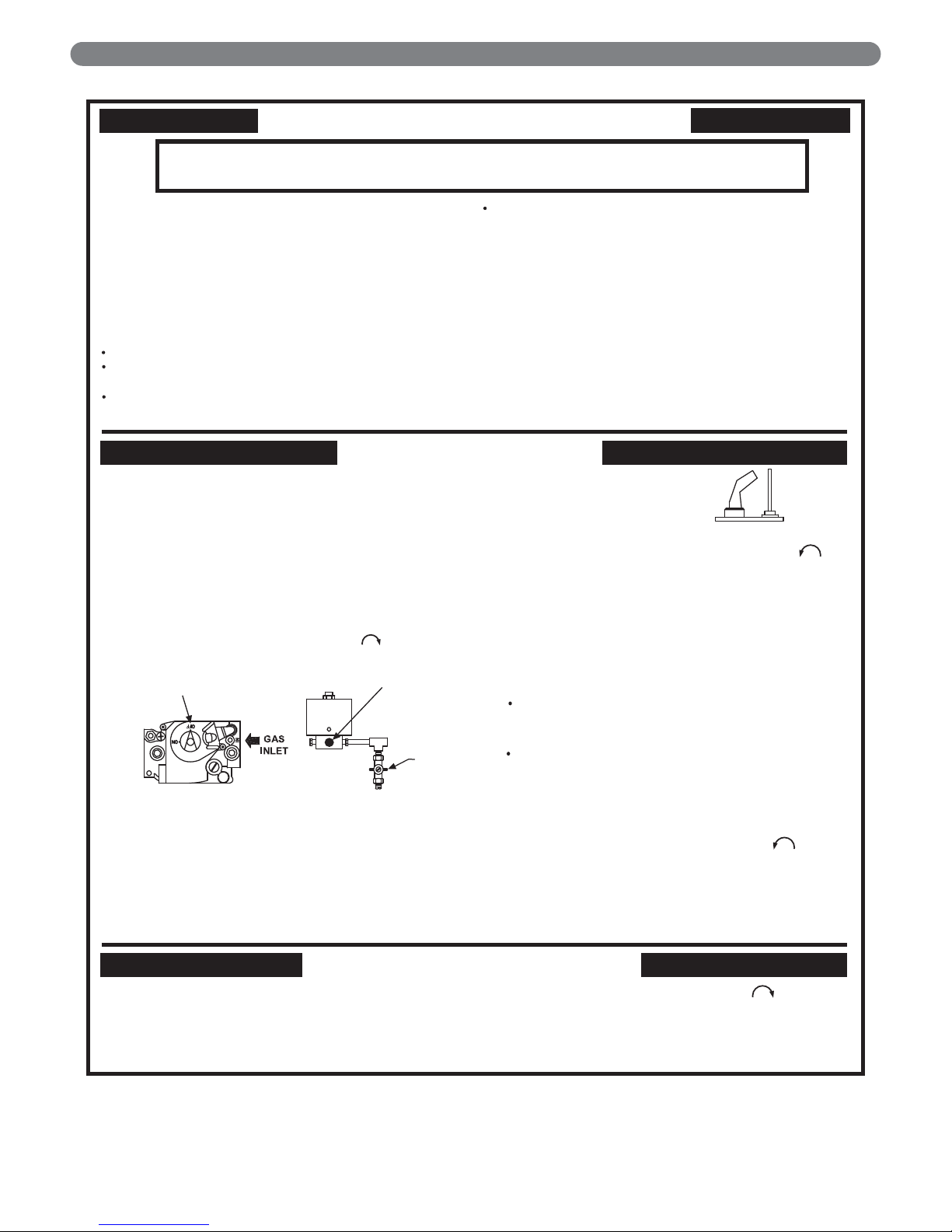
Gas Control Knob
(shown in "OFF"
position
Red Reset Button
6. Wait five (5) minutes to clear out any gas. Then smell
for gas, including near the floor. If you smell gas,
STOP! Follow "B" in the safety information above on
this label. If you don't smell gas, go to the next step.
7. Remove the pilot access panel, if supplied, located
below and behind the gas valve directly above burner
tubes.
TO TURN OFF GAS TO APPLIANCE
8. Find pilot - follow metal tube
from gas valve. The pilot is
between two burner tubes
Pilot Burner
9. Turn the gas control knob counterclockwise to
"PILOT".
10. Push in red reset button all the way and hold in.
Immediately light the pilot with a match. Continue to
hold the reset button in for about one (1) minute after
the pilot is lit. Release button and it will pop back up.
Pilot should remain lit. If it goes out, repeat steps 5
through 10.
If button does not pop up when released, stop and
immediately call your service technician or gas
supplier.
If the pilot will not stay lit after several tries, turn the
gas control knob to "OFF" and call your service
technician or gas supplier.
11. Replace pilot access panel, if applicable.
12. Turn gas control knob counterclockwise to "ON".
13. Replace control access panel, if applicable.
14. Turn on all electric power to the appliance.
15. Set thermostat to desired setting.
1. Set the thermostat to lowest setting.
2. Turn off all electric power to the appliance if service is
to be performed.
3. If the gas valve is not visible, remove the control access
panel.
4. Turn the gas control knob clockwise to "OFF".
5. Replace control access panel, if applicable.
A. This appliance has a pilot which must be lighted by
hand. When lighting the pilot, follow these
instructions exactly.
B. BEFORE LIGHTING smell all around the appliance area
for gas. Be sure to smell next to the floor because
some gas is heavier than air and will settle on the
floor.
WHAT TO DO IF YOU SMELL GAS
Do not try to light any appliance
Do not touch any electric switch;
do not use any phone in your building
Immediately call your gas supplier from a neighbor's
phone. Follow the gas supplier's instructions.
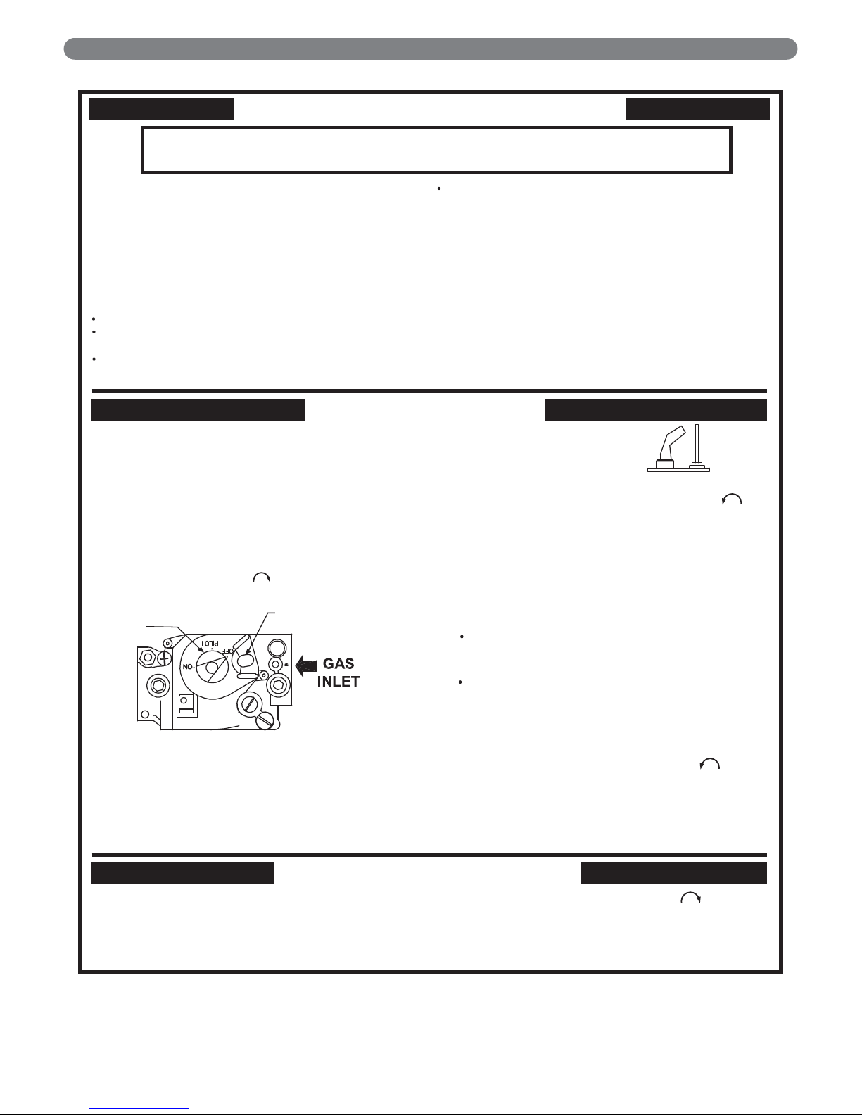
Figure 8.2 Standing Pilot - 63 Nat/LP, 64 LP Gas
Page 38
36
BOILER OPERATION
VR8304 L62 9361 REV.0
If you cannot reach your gas supplier, call the fire
department.
C. Use only your hand to push in or turn the gas control
knob. Never use tools. If the knob will not push in or
turn by hand, don't try to repair it, call a qualified
service technician. Force or attempted repair may
result in a fire or explosion.
D. Do not use this appliance if any part has been under
water. Immediately call a qualified service technician
to inspect the appliance and to replace any part of the
control system and any gas control which has been
under water.
WARNING: If you do not follow these instructions exactly, a fire or explosion may
result causing property damage, personal injury, or loss of life.
FOR YOUR SAFETY READ BEFORE LIGHTING
LIGHTING INSTRUCTIONS
1. STOP! Read the safety information above on this
label.
2. Set the thermostat to lowest setting.
3. Turn off all electric power to the appliance.
4. If the gas valve is not visible, remove control access
panel.
5. If the gas control knob and pilot cock are not in the
"OFF" position, turn both clockwise to "OFF".
6. Wait five (5) minutes to clear out any gas. Then smell
for gas, including near the floor. If you smell gas,
STOP! Follow "B" in the safety information above on
this label. If you don't smell gas, go to the next step.
7. Remove the pilot access panel, if supplied, located
below and behind the gas valve directly above burner
tubes.
TO TURN OFF GAS TO APPLIANCE
8. Find pilot - follow metal tube
from gas valve. The pilot is
between two burner tubes
Pilot Burner
9. Turn the pilot cock handle counterclockwise to
"PILOT".
10. Push in red reset button on thermopilot valve all the
way and hold in. Immediately light the pilot with a
match. Continue to hold the reset button in for about
one (1) minute after the pilot is lit. Release button and
it will pop back up. Pilot should remain lit. If it goes
out, repeat steps 5 through 10.
If button does not pop up when released, stop and
immediately call your service technician or gas
supplier.
If the pilot will not stay lit after several tries, turn the
gas control knob to "OFF" and call your service
technician or gas supplier.
11. Replace pilot access panel, if applicable.
12. Turn gas control knob counterclockwise to "ON".
13. Replace control access panel, if applicable.
14. Turn on all electric power to the appliance.
15. Set thermostat to desired setting.
1. Set the thermostat to lowest setting.
2. Turn off all electric power to the appliance if service is
to be performed.
3. If the gas valve is not visible, remove the control access
panel.
4. Turn the gas control knob clockwise to "OFF".
5. Replace control access panel, if applicable.
A. This appliance has a pilot which must be lighted by
hand. When lighting the pilot, follow these
instructions exactly.
B. BEFORE LIGHTING smell all around the appliance area
for gas. Be sure to smell next to the floor because
some gas is heavier than air and will settle on the
floor.
WHAT TO DO IF YOU SMELL GAS
Do not try to light any appliance
Do not touch any electric switch;
do not use any phone in your building
Immediately call your gas supplier from a neighbor's
phone. Follow the gas supplier's instructions.
Gas Control Knob
(shown in "OFF"
position)
Red Reset
Button
Thermopilot
Valve
Pilot Cock
(shown in
"OFF"
position)
Figure 8.3 Standing Pilot - 64 Nat Gas
Page 39
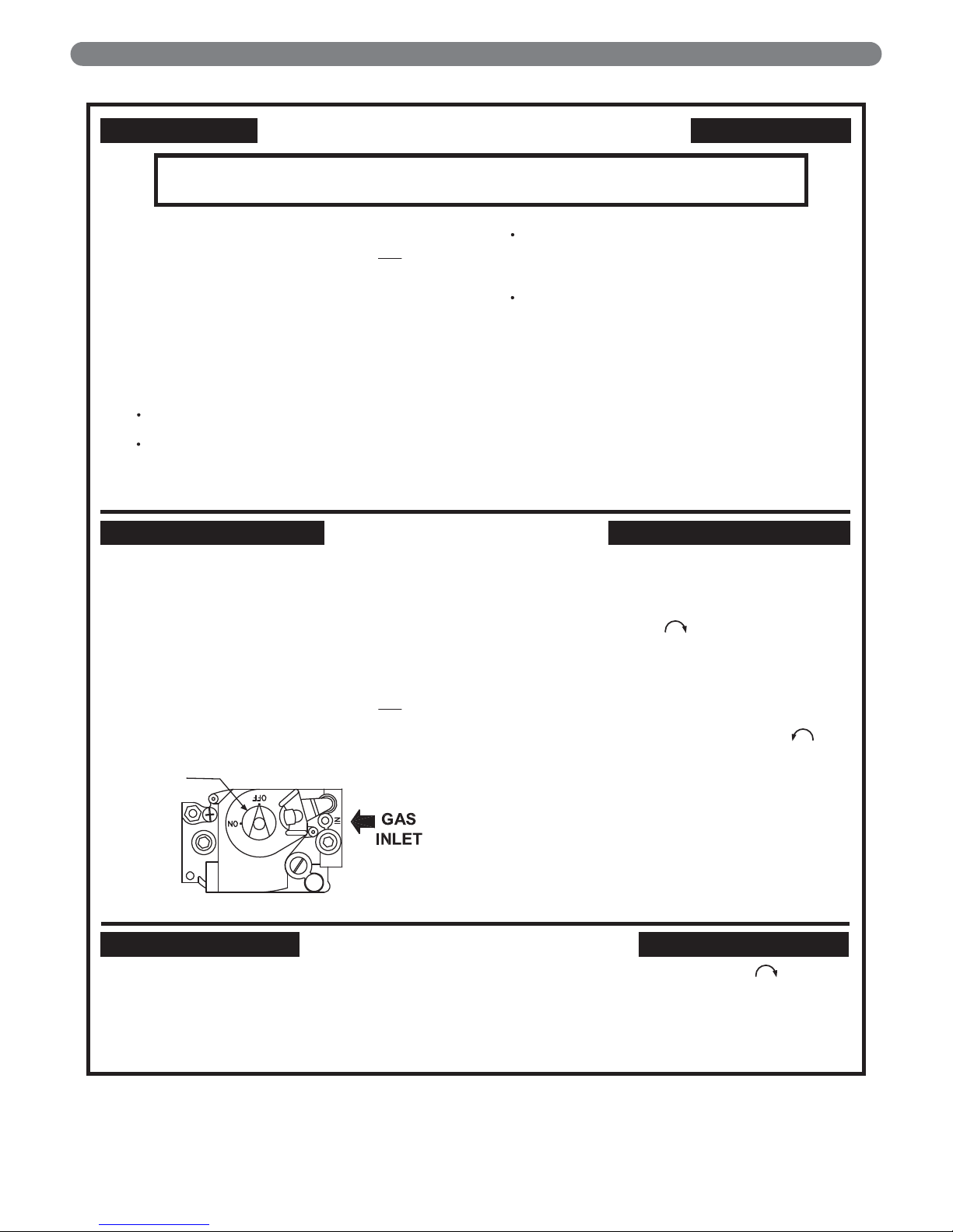
37
BOILER OPERATION
HSP VR8204/VR8304 9181R REV.2
FOR YOUR SAFETY READ BEFORE LIGHTING
WARNING: If you do not follow these instructions exactly, a fire or explosion may
result causing property damage, personal injury, or loss of life.
OPERATING INSTRUCTIONS
TO TURN OFF GAS TO APPLIANCE
1. Set the thermostat or operating control to lowest
setting.
2. Turn off all electric power to the appliance if service is
to be performed.
3. If the gas valve is not visible, remove the control
access panel.
4. Turn the gas control knob clockwise to "OFF".
5. Replace control access panel, if applicable.
1. STOP! Read the safety information above on this
label.
2. Set the thermostat or operating control to lowest
setting.
3. Turn off all electric power to the appliance.
4. This appliance is equipped with an ignition device
which automatically lights the pilot. Do not try to light
the pilot by hand.
5. If the gas valve is not visible, remove control access
panel.
6. If the gas control knob is not in the "OFF" postion,
turn the knob clockwise to "OFF".
7. Wait five (5) minutes to clear out any gas. Then smell
for gas, including near the floor. If you smell gas,
STOP! Follow "B" in the safety information above on
this label. If you don't smell gas, go to the next step.
8. Turn the gas control knob counterclockwise to
"ON".
9. Replace control access panel, if applicable.
10. Turn on all electrical power to the appliance.
11. Set thermostat or operating control to desired setting.
12. If the appliance will not operate, follow the
instructions "To Turn Off Gas To Appliance"
and call your service technician or gas supplier.
A. This appliance is equipped with an ignition device
which automatically lights the pilot. Do not try to
light the pilot by hand.
B. BEFORE OPERATING smell all around the appliance
area for gas. Be sure to smell next to the floor
because some gas is heavier than air and will settle
on the floor.
WHAT TO DO IF YOU SMELL GAS
Do not try to light any appliance
Do not touch any electric switch;
do not use any phone in your building.
Immediately call your gas supplier from a
neighbor's phone. Follow the gas supplier's
instructions.
If you cannot reach your gas supplier,
call the fire department.
C. Use only your hand to push in or turn the gas control
knob. Never use tools. If the knob will not push in or
turn by hand, don't try to repair it, call a qualified
service technician. Force or attempted repair may
result in a fire or explosion.
D. Do not use this appliance if any part has been under
water. Immediately call a qualified service technician
to inspect the appliance and to replace any part of the
control system and any gas control which has been
under water.
Gas Control Knob
(shown in "OFF"
position)
Figure 8.4 Spark Ignition - 63-03 thru 64-08 Nat/LP, 64-09 thru 64-12 LP Gas
Page 40
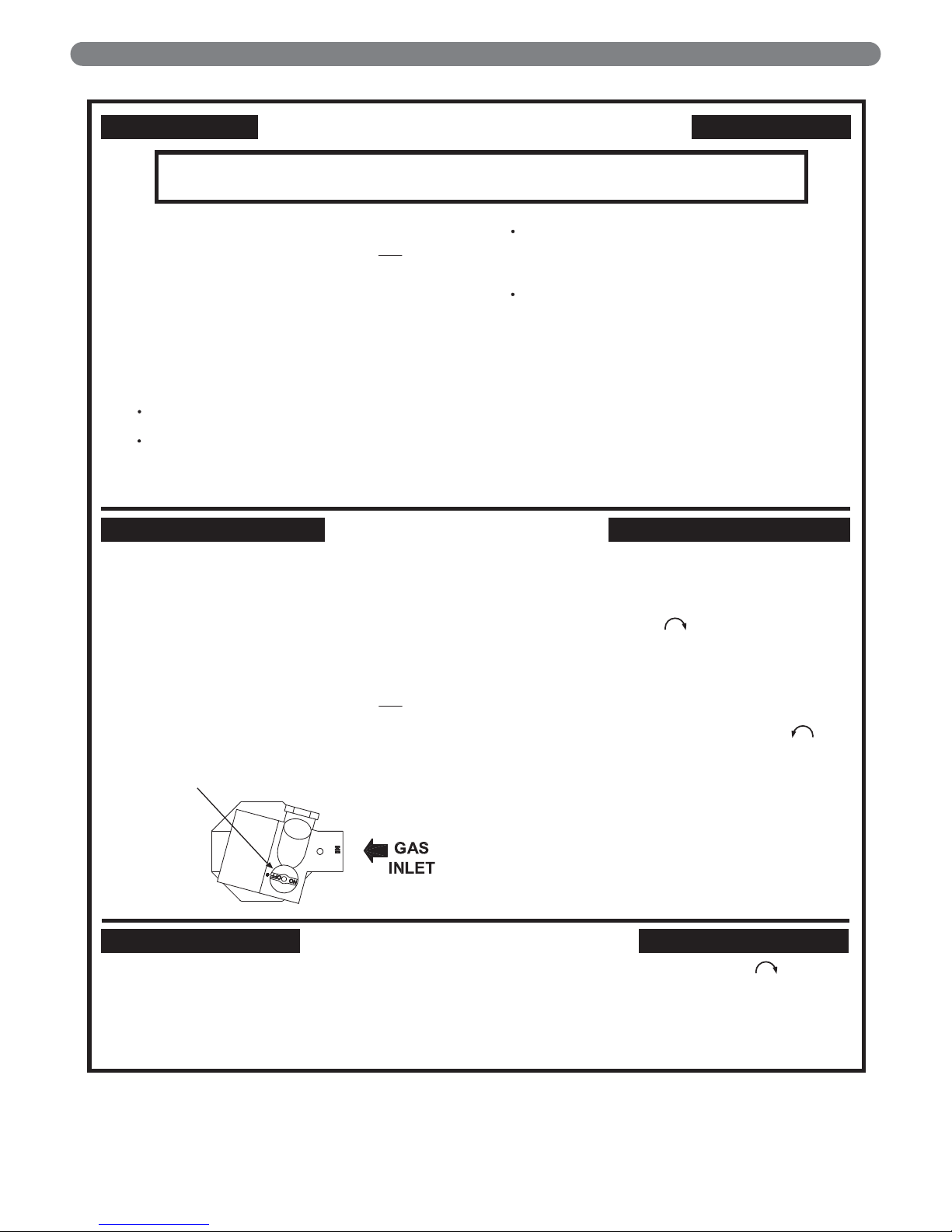
38
BOILER OPERATION
SPRK 7000DERHC 9363R REV.0
FOR YOUR SAFETY READ BEFORE LIGHTING
WARNING: If you do not follow these instructions exactly, a fire or explosion may
result causing property damage, personal injury, or loss of life.
OPERATING INSTRUCTIONS
TO TURN OFF GAS TO APPLIANCE
1. Set the thermostat or operating control to lowest
setting.
2. Turn off all electric power to the appliance if service is
to be performed.
3. If the gas valve is not visible, remove the control
access panel.
4. Turn the gas control knob clockwise to "OFF".
5. Replace control access panel, if applicable.
1. STOP! Read the safety information above on this
label.
2. Set the thermostat or operating control to lowest
setting.
3. Turn off all electric power to the appliance.
4. This appliance is equipped with an ignition device
which automatically lights the pilot. Do not try to light
the pilot by hand.
5. If the gas valve is not visible, remove control access
panel.
6. If the gas control knob is not in the "OFF" postion,
turn the knob clockwise to "OFF".
7. Wait five (5) minutes to clear out any gas. Then smell
for gas, including near the floor. If you smell gas,
STOP! Follow "B" in the safety information above on
this label. If you don't smell gas, go to the next step.
8. Turn the gas control knob counterclockwise to
"ON".
9. Replace control access panel, if applicable.
10. Turn on all electrical power to the appliance.
11. Set thermostat or operating control to desired setting.
12. If the appliance will not operate, follow the
instructions "To Turn Off Gas To Appliance"
and call your service technician or gas supplier.
A. This appliance is equipped with an ignition device
which automatically lights the pilot. Do not try to
light the pilot by hand.
B. BEFORE OPERATING smell all around the appliance
area for gas. Be sure to smell next to the floor
because some gas is heavier than air and will settle
on the floor.
WHAT TO DO IF YOU SMELL GAS
Do not try to light any appliance
Do not touch any electric switch;
do not use any phone in your building.
Immediately call your gas supplier from a
neighbor's phone. Follow the gas supplier's
instructions.
If you cannot reach your gas supplier,
call the fire department.
C. Use only your hand to push in or turn the gas control
knob. Never use tools. If the knob will not push in or
turn by hand, don't try to repair it, call a qualified
service technician. Force or attempted repair may
result in a fire or explosion.
D. Do not use this appliance if any part has been under
water. Immediately call a qualified service technician
to inspect the appliance and to replace any part of the
control system and any gas control which has been
under water.
Gas Control Knob
(shown in "OFF"
position)
Figure 8.5 Spark Ignition - 64-09 thru 64-12 Nat Gas
Page 41

39
MAINTENANCE
9. MAINTENANCE
WARNING
Product Safety Information
Refractory Ceramic Fiber Product
This appliance contains materials made from refractory ceramic fibers (RCF). Airborne RCF
fibers, when inhaled, have been classified by the International Agency for Research on
Cancer (IARC), as a possible carcinogen to humans. After the RCF materials have been
exposed to temperatures above 1800°F, they can change into crystalline silica, which has
been classified by the IARC as carcinogenic to humans. If particles become airborne during
service or repair, inhalation of these particles may be hazardous to your health.
Avoid Breathing Fiber Particulates and Dust
Suppliers of RCF recommend the following precautions be taken when handling these
materials:
Precautionary Measures:
Provide adequate ventilation.
Wear a NIOSH/MSHA approved respirator.
Wear long sleeved, loose fitting clothing and gloves to prevent skin contact.
Wear eye goggles.
Minimize airborne dust prior to handling and removal by water misting the material and
avoiding unnecessary disturbance of materials.
Wash work clothes separately from others. Rinse washer thoroughly after use.
Discard RCF materials by sealing in an airtight plastic bag.
First Aid Procedures:
Inhalation: If breathing difficulty or irritation occurs, move to a location with fresh clean air.
Seek immediate medical attention if symptoms persist.
Skin Contact: Wash affected area gently with a mild soap and warm water. Seek immediate
medical attention if irritation persists.
Eye Contact: Flush eyes with water for 15 minutes while holding eyelids apart. Do not rub
eyes. Seek immediate medical attention if irritation persists.
Ingestion: Drink 1 to 2 glasses of water. Do not induce vomiting. Seek immediate medical
attention.
Page 42
40
MAINTENANCE
A. GENERAL
1. Disconnect this boiler from the gas supply piping
during any pressure testing of the gas system.
2. Check pipes adjacent to cold walls or in unheated
spaces. Insulate and tape them if necessary to be
sure they can’t freeze up. Keeping the water moving
at all times will reduce the likelihood of freezing.
3. If there is considerable foreign matter in the boiler
water, the boiler should be shut down and allowed to
cool, then drained and thoroughly flushed out. Use
the drain valve at the bottom of the right side to
drain the boiler. Pipe the drain cock to a suitable
drain or containment device (if antifreeze is used).
Flush the system to remove remaining matter. If there
is evidence that hard scale has formed on the
internal surfaces, the boiler should be cleaned by
chemical means as prescribed by a qualified water
treatment specialist.
4. There must be no signs of continuous wetness at the
chimney. If signs of continuous wetness are observed,
a qualified service agency must be consulted to
modify the vent configuration to prevent the formation
of condensate, which may damage the vent pipe.
B. DAILY MAINTENANCE (WITH BOILER
OPERATING)
Daily boiler observation can be performed by the owner.
If any potential problems are found, a qualified installer
or service technician/agency must be notified.
1. Remove any combustible materials, gasoline and
other flammable liquids and substances that generate
flammable vapors from the area where the boiler is
contained. Make certain that the boiler area has
ample air for combustion and ventilation and that
there are no obstructions to the free flow of air to
and from the boiler.
2. Observe general boiler conditions (unusual noises,
vibrations, etc.)
3. Observe operating temperature and/or pressure on
the gauge located on the right side of the boiler.
Boiler pressure should never be higher than 5 psi
below the rating shown on the safety relief valve.
The valve rating can be found on the top of the
safety relief valve (see Figure 6.1 or 6.4 for location
of the safety relief valve). Boiler temperature should
never be higher than 250°F.
4. Check for water leaks in boiler and system piping.
5. Smell around the appliance area for gas. If you smell
gas, follow the “To Turn Off Gas to Appliance”
procedure listed in the Lighting/Operating
Instructions in Section 8.
C. WEEKLY MAINTENANCE (WITH BOILER
OPERATING)
1. Flush float-type low-water cut-off (if used) to remove
sediment from the float bowl as stated in the
manufacturer’s instructions.
D. MONTHLY MAINTENANCE (WITH BOILER
OPERATING)
1. Check boiler room floor drains for proper
functioning.
2. Check function of the safety relief valve (monthly
unless specified otherwise by manufacturer) by
performing the following test:
a. Check valve piping to determine that it is
properly installed and supported.
b. Check boiler operating temperature and pressure.
c. Lift the try lever on the safety relief valve to the
full open position and hold it for at least five
seconds or until clean water is discharged.
d. Release the try lever and allow the valve to close.
If the valve leaks, operate the lever two or three
times to clear the valve seat of foreign matter. It
may take some time to determine if the valve has
shut completely.
e. If the valve continues to leak, it must be replaced
before the boiler is returned to operation.
f. Check that operating pressure and temperature
have returned to normal.
g. Check again to confirm that valve has closed
completely and is not leaking.
3. Test low-water cut-off (if used) as described by the
manufacturer.
4. Test limit by lowering the limit set point until the
main burners shut down. When proper operation is
confirmed, return the set point to the desired setting.
5. Test function of gas safety shut-off features as
described by gas valve and ignition control
manufacturer.
6. Cycle the boiler at least once and check operation of
the vent damper.
E. ANNUAL MAINTENANCE (BEFORE
START OF HEATING SEASON)
1. Check flueways and burners for cleanliness and
clean if necessary. Use the following procedure if
cleaning is required:
a. Refer to the Lighting/Operating Instructions in
Section 8 “To Turn Off Gas to Appliance.”
b. Turn off all electrical power to the boiler.
c. Remove burners and brush gas outlet ports
lightly using a soft bristle brush.
When servicing or replacing components, be
absolutely certain that the following conditions are
met:
●
Water, gas and electricity are off.
●
The boiler is at room temperature.
●
There is no pressure in the boiler.
DANGER
Page 43

41
MAINTENANCE
d. Remove the vent pipe, vent damper, top jacket
panels and flue collector.
e. Brush flueways with wire brush.
f. To the extent possible, inspect inside of vent pipe
and vent damper for obstructions in flow or vent
damper movement. Remove or replace as
necessary.
g. When replacing the flue collector, be certain that
the blanket seal between the flue collector and
top section makes a tight seal to prevent leakage
of the products of combustion.
h. Re-install the top of the jacket, vent damper and
vent pipe.
i. Connect blocked vent switch wiring harness to
blocked vent switch.
k. Re-install burners.
2. Inspect entire venting system for corrosion, support
and joint integrity. Repair as necessary.
3. Check the pilot and main burner flame. See Figure
8.1. The pilot should provide a steady flame
enveloping 3/8" to 1/2" of the flame sensor. If
required, adjust the pilot as stated in the gas valve
manufacturer’s instructions. The main burner flame
inner cone should be approximately 1-1/2" high and
should have a very sharp, blue color characteristic.
F. AS REQUIRED MAINTENANCE
Test and inspect low water cut-off(s) per manufacturer’s
instructions.
If the steam boiler water level is erratic and dirt &
deposits appear in the water gauge glass, skim the boiler
as described in Section 8.
Page 44
42
TROUBLE SHOOTING – SERVICE TIPS
10. TROUBLESHOOTING – SERVICE TIPS
Problem Possible Cause Suggested Remedy
Defective Thermocouple Replace
Heavy Draft Blowing across Pilot Redirect Air Movement or Eliminate
Plugged Pilot Orifice Replace Orifice
Pilot Outage Check Manual Pilot Valve
Check Main Gas Shut-Off Valve
No Gas
Check Manual Meter Valve
Consult Gas Company
Defective Thermopilot Switch Replace
Defective Ignition Control Replace
No Power
Check Power Source with Meter
Check Fuses
Defective Gas Valve Replace
Low Water Level in Boiler
Check for Leaks
or System Causing Low Water Cut-off to
Check Feeder (if Supplied)
Function
Defective Ignition Control Replace
High Gas Pressure Switch Open Check Switch Setting
(if Provided) Check Manifold Gas Pressure
Low Gas Pressure Switch Open Check Switch Setting
(if Provided) Check Manifold Gas Pressure
No Power
Check Power Source with Meter
Check Fuses
Defective Gas Valve Replace
Pilot Out
Relight Pilot
(May have defective pilot valve or relay)
Low Water in Boiler
Check for Leaks
or System Causing Low Water Cut-off to
Check Feeder (if Supplied)
Function
Defective Thermopilot Switch Replace
Defective Thermocouple Replace
High Gas Pressure Switch Open Check Switch Setting
(if Provided) Check Manifold Gas Pressure
Low Gas Pressure Switch Open Check Switch Setting
(if Provided) Check Inlet Gas Pressure
Main Gas Valve Will Not Open
(Spark Ignited Pilot)
Main Gas Valve Will Not Open
(Standing Pilot)
Page 45
43
TROUBLE SHOOTING – SERVICE TIPS
Problem Possible Cause Suggested Remedy
Air Adjustment Screws Turned in Too Far Adjust Screws Out
Low Gas Pressure in Manifold Adjust Main Gas Pressure Regulator
(Insufficient Air Injection) or Check Line Pressure
Burner Ports Partially Closed
Replace Burners or Clean Ports
Burner(s) Burning with Yellow Flame
(Rust, Dirt, Lint, etc)
Check Size of Combustion Air Openings
to Room
Insufficient Air for Combustion
If Undersized, Correct as Required
Check for Negative Pressure in Boiler Room
Oversized Burner Orifice Install Correct Orifice
High Gas Pressure in Manifold Adjust Main Gas Pressure Regulator
Insufficient Draft - Chimney Too Low Increase Height or Add Induced Draft Fan
Insufficient Draft - Chimney Too Small Replace Chimney or Add Induced Draft Fan
Insufficient Draft - Blockage in Chimney or Vent Repair Chimney or Vent
Gas Spillage from Insufficient Draft - Downdraft Caused by
Draft Hood Relief Opening
Chimney Location with Respect to Other Install Chimney Cap
Buildings, Roofs, etc.
Negative Pressure in Boiler Room Remove Exhaust Fan or
(Due to Exhaust Fan or Duct System) Isolate Fan From Boiler Room
Insufficient Combustion Air Openings
Provide Correctly Sized Combustion and
Ventilation Air Openings
Main Gas Valve Opens
Manual Valve Closed at Gas Train Open Valve
But No Gas Flows
Manual Valve Closed at Meter Open Valve
Test Firing Valve Closed (if Provided) Open Valve
Leaks in System Repair Leaks or Replace Piping as Required
Expansion tank (diaphragm or bladder type) Check Charge Pressure, Correct if Required
charge pressure not right
Air compression tank waterlogged or
diaphragm or bladder defective on Replace tank
expansion tank
Fill valve not working or set for too high a
Check Fill Valve, Replace if Necessary
cold fill pressure, causing relief valve to weep
Temperature control differential too narrow Adjust Control Differential
Sags in Steam Piping or not enough Pitch Correct Piping Condition
Concentric reducers causing condensate pooling Correct Piping
Drip trap failed closed Replace Trap or Trap Element
Dry returns wetted due to new boiler water line
Correct Piping or Install Feed System and Traps
higher than old boiler
No drip line on the back side of a back-pitched
Install Drip Line and Trap
motorized valve
System or Boiler Overfilling or
Excessive Make-up Water
(Water Boilers)
Water Hammer On Start-Up
(Steam Boilers)
Rapid Cycling
(Water Boilers)
Page 46
44
TROUBLE SHOOTING – SERVICE TIPS
Problem Possible Cause Suggested Remedy
Clogged returns on gravity system Clean or Re-Pipe Return Line(s)
Incorrect near-boiler piping causing wet steam
Correct Piping per Manual
to system
Trap failed open, allowing steam to enter returns Replace Trap or Trap Element
{Radiator Hammer} Large radiator may be
Use smaller Air Vent or Use Two Small Vents in
vented too quickly
Place of One Large Vent, One Mounted Higher
than the Other
Long nipple at Hartford Loop Replace with Close Nipple
Water leg or back slope in return line to receiver
Correct Piping
tank, causing water pocketing
Trap installed at receiver tank, causing water Remove Trap at Tank, Install Drip Traps and
trapping in return Radiator Traps where Required
Boiler feed pump or condensate pump feed rate
Throttle Flow Rate
too fast, causing spraying into equalizer
No drip on the inlet side of a forward pitched
Add Drip Line and Trap
motorized valve
Uninsulated steam piping, causing excessive
Insulate Steam Pipes
condensate loads
Close nipple on Hartford Loop too high Repipe 2" to 4" (5cm to 10cm) Below Water Line
Uninsulated steam piping in boiler room, but
system piping insulated, causing vacuum Insulate Steam Pipes
condition on shut-down
Poor circulation in the boiler due to sludge
Clean and Blowdown the Boiler
accumulation
Main vents not working
Replace Main Vents, Repiping away from End
of Lines if Needed
Drip Traps failed closed Replace Traps or Trap Elements
Radiator traps failed open, allowing pressurization
Replace Traps or Trap Elements
of the returns
Water legs or back slope in return lines to receiver
Correct Piping
tank, preventing air from venting out receiver vent
Boiler pressure too high, causing air vents to lock
Reduce Operating Pressure
up or blowing water loop seals
New boiler water content smaller than old boiler
Install Boiler Feed System with Receiver Tank
Large enough for Condensate
Boiler water feed rate or pump rate too fast
causing water level to collapse (due to collapse of Reduce Feed Rate
steam bubbles in boiler water)
Foaming, priming or surging due to poor
Clean the Boiler
water quality
Poor water quality, causing foaming and surging Clean the Boiler
Incorrect near-boiler piping, such as undersized
Pipe per Manual
or incorrectly placed risers
Boiler water feed rate or pump rate too fast Reduce Feed Rate
Air vents or traps not venting air, preventing
steam from getting to radiation and pressurizing Replace Vents or Traps
the air pocket
Pressure differential on pressure control too close Adjust Control Differential
Nuisance outages of water level control due to
See Excessive Water Level Bounce Above
boiler water level bounce
Water Hammer During Mid-Cycle
(Steam Boilers)
Water Hammer on Shut-Down
(Steam Boilers)
No Heat or Poor Heat
Distribution in the Building
(Steam Boilers)
System or Boiler Overfilling or Flooding
(Steam Boilers)
Excessive Water Level Bounce
(Steam Boilers)
Rapid Cycling
(Steam Boilers)
Hammering in the Boiler
(Steam Boilers)
Page 47
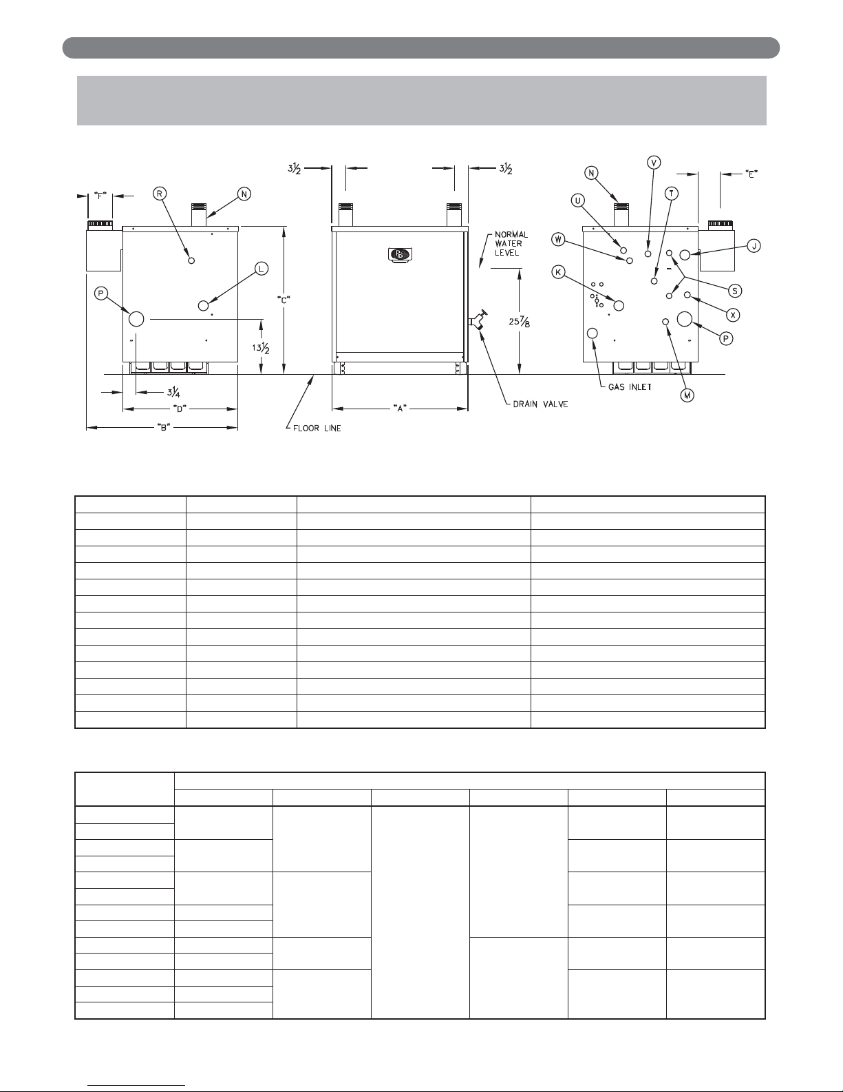
45
BOILER DIMENSIONS & RATINGS
Boiler
Model
Dimensions (Inches)
“A” “B” “C” “D” “E” “F”
63-03L
16-1/8
37-1/4
36-3/8
28-1/8
5-5/8 6
63-03
63-04L
20-3/8 5-1/8 7
63-04
63-05L
24-5/8
39-1/4
6-5/8 8
63-05
63-06 28-7/8
6-1/8 9
64-07 33-1/8
64-08 37-3/8
43-1/8
30-1/8
7-1/2 10
64-09 41-5/8
64-10 45-7/8
45-1/8 8-1/2 12
64-11 50-1/8
64-12 54-3/8
11. BOILER DIMENSIONS & RATINGS
Figure 11.1: Dimensions and Tapping Locations
Table 11.1: Tapping Sizes & Functions
Table 11.2: Dimensions
Tap I D Size NPT Steam Water
J 1-1/4" Skim Tapping Skim Tapping
K 1" Tank Supply/Limit N/A
L 1" Tank Return N/A
M 3/4" Boiler Drain Boiler Drain
N 3" Supply Supply
P 2-1/2" Return Return
R 3/4" Safety Valve Relief Valve
S 1/2" Gauge Glass N/A
T 3/4" Primary Probe Low Water Cut-Off N/A
U 3/4" Primary Limit Primary Limit
V 3/4" Secondary Limit Pressure/Temperature Gauge
W 3/4" Pressure Gauge Secondary Limit
X 3/4" Secondary Probe Low Water Cut-Off N/A
Page 48
46
BOILER DIMENSIONS & RATINGS
Table 11.3: Series 63™ Boiler Ratings
1. Net I=B=R Ratings are based on DOE Heating Capacity less an allowance for normal piping and pickup as determined by
the Testing and Rating Standard for Low Pressure Cast Iron Heating Boilers of the Hydronics Institute. Water ratings are based
on a piping and pickup factor of 1.15. Steam ratings are based on a piping and pickup factor of 1.33. Consult PB Heat
before selecting a boiler for gravity hot water installations or for installations having unusual piping and pickup requirements
such as exposed piping, night set back, etc. Ratings shown are for elevations up to 2,000 feet. For elevations above 2,000
feet, ratings should be reduced at the rate of 4% for each 1,000 feet above sea level.
2. Minimum Natural Gas Inlet Pressure exceptions: 63-04 STDG 5.3"; 63-06 STDG 5.5"; 63-06 SPRK 5.3".
3. Heating Capacity and Annual Fuel Utilization Efficiency (AFUE) ratings are based on U.S. Government tests. Before
purchasing this appliance, read important information about its estimated annual energy consumption or energy efficiency
rating that is vailable from your retailer.
NOTE: Minimum Inlet Gas Pressure: Natural Gas @ 5.0 in. W.C.², LP Gas @ 11.0 in. W.C.
Series 63™
Boiler
Model
Input,
MBH
Heating Capacity³ Net I=B=R Ratings¹
Standing Pilot
AFUE³
Spark Ignition
AFUE³
Water,
MBH
Steam,
MBH
Steam,
sqft
Steam,
MBH
Water,
MBH
Water,%Steam,%Water,%Steam,
%
63-03L 88.5 73 74 233 56 63 80.9 80.6 82.4 83.0
63-03 118.0 99 98 308 74 86 82.1 81.2 83.5 82.6
63-04L 147.5 123 123 383 92 107 81.4 80.6 82.7 82.6
63-04 177.0 148 147 458 110 129 82.1 81.0 83.4 82.4
63-05L 206.5 172 171 533 128 150 81.9 80.7 82.9 82.3
63-05 236.0 198 196 613 147 172 82.2 80.9 83.3 82.2
63-06 287.5 241 238 746 179 210 82.3 80.7 83.2 82.0
Water
Content
Approx.
Shipping
Weight,
lb
Water,
gal
Steam,
gal
13.2 9.3 465
13.2 9.3 465
15.6 10.8 576
15.6 10.8 576
18.0 12.4 700
18.0 12.4 700
20.4 13.9 812
Series 64™
Boiler
Model
Input,
MBH
Gross Output³ Net I=B=R Ratings¹
Thermal
Efficiency
Combustion
Efficiency³
Water,
MBH
Steam,
MBH
Steam,
sqft
Steam,
MBH
Water,
MBH
Water,%Steam,%Water,%Steam,
%
64-07 345 286 274 858 206 249 81.0 79.4 83.0 82.5
64-08 399 331 318 996 239 288 81.0 79.6 83.0 82.5
64-09 460 382 367 1146 275 332 81.0 79.7 83.0 82.5
64-10 518 430 413 1292 310 374 81.0 79.8 83.0 82.5
64-11 575 477 459 1433 344 415 81.1 79.8 83.0 82.5
64-12 633 525 506 1583 380 457 81.0 79.9 83.0 82.4
Water
Content
Approx.
Shipping
Weight,
lb
Water,
gal
Steam,
gal
22.8 15.5 945
25.2 17.0 1081
27.6 18.6 1218
30.0 20.1 1354
32.4 21.7 1490
34.8 23.2 1527
1. Net I=B=R Ratings are based on Gross Output less an allowance for normal piping and pickup as determined by the Testing
and Rating Standard for Low Pressure Cast Iron Heating Boilers of the Hydronics Institute. Water ratings are based on a
piping and pickup factor of 1.15. Steam ratings are based on a piping and pickup factor of 1.33. Consult PB Heat before
selecting a boiler for gravity hot water installations or for installations having unusual piping and pickup requirements such as
exposed piping, night set-back, etc. Ratings shown are for elevations up to 2,000 feet. For elevations above 2,000 feet, ratings
should be reduced at the rate of 4% for each 1,000 feet above sea level.
2. Minimum Natural Gas Inlet Pressure: 5.0 in. W.C. except for 64-08 STDG 5.3 in., 64-12 STDG 5.1 in.
3. Combustion efficiency and gross output are determined in accordance with ANSI Z21.13 / CSA 4.9, Gas-Fired Low-Pressure
Steam and Hot Water Boilers.
Table 11.4: Series 64™ Boiler Ratings
Page 49
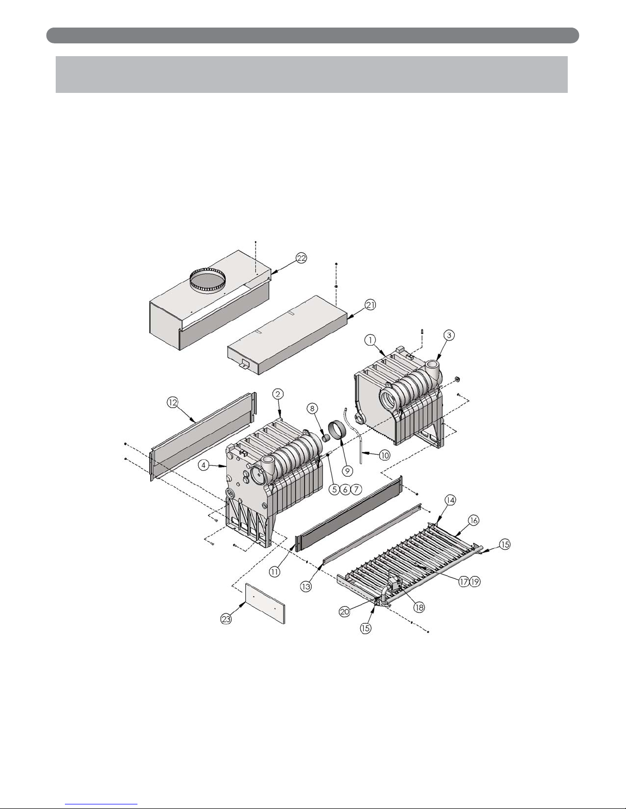
47
REPAIR PARTS
12. REPAIR PARTS
Figure 12.1
Repair parts are available from your installer or by contacting PB Heat, LLC,
131 S. Church, Bally, PA 19503.
Note: Remember to include boiler model number and serial number when ordering parts.
Page 50
48
REPAIR PARTS
Description
Quantity
Required
Stock
Code
1 Intermediate Section – w/out Draw Lugs – 90028
2 Intermediate Section – w/ Draw Lugs (64) – 90029
3 Right Hand Section – 90030
4 Left Hand Section – 90031
5 Draw Rod 5/8"-11 x 8" (64) – 7797
6 Draw Rod Nut 5/8"-11 (64) – 51567
7 Draw Rod Washer (64) – 7289
8 2" Push Nipple – 51543
9 6" Push Nipple – 51546
10 High Temperature Sealing Rope 1/2" – 51211
– 63-03L Block Assembly – 90684
– 63-03 Block Assembly – 90684
– 63-04L Block Assembly – 90685
– 63-04 Block Assembly – 90685
– 63-05L Block Assembly – 90686
– 63-05 Block Assembly – 90686
– 63-06 Block Assembly – 90687
– Left Hand 64-07 Split Block – 90904
– Right Hand 64-07 Split Block – 90906
– Left Hand 64-08 Split Block – 90904
– Right Hand 64-08 Split Block – 90907
– Left Hand 64-09 Split Block – 90904
– Right Hand 64-09 Split Block – 90908
– Left Hand 64-10 Split Block – 90905
– Right Hand 64-10 Split Block – 90907
– Left Hand 64-11 Split Block – 90905
– Right Hand 64-11 Split Block – 90908
– Left Hand 64-12 Split Block – 90905
– Right Hand 64-12 Split Block – 90909
11
Base Front Panel – 63-03 – 50324
Base Front Panel – 63-04 – 50325
Base Front Panel – 63-05 – 50326
Base Front Panel – 63-06 – 50327
Base Front Panel – 64-07 – 50328
Base Front Panel – 64-08 – 50329
Base Front Panel – 64-09 – 50330
Base Front Panel – 64-10 – 50331
Base Front Panel – 64-11 – 50332
Base Front Panel – 64-12 – 50333
12
Base Rear Panel – 63-03 – 61180
Base Rear Panel – 63-04 – 61181
Base Rear Panel – 63-05 – 61182
Base Rear Panel – 63-06 – 61183
Base Rear Panel – 64-07 – 61184
Base Rear Panel – 64-08 – 61185
Base Rear Panel – 64-09 – 61186
Base Rear Panel – 64-10 – 61187
Base Rear Panel – 64-11 – 61188
Base Rear Panel – 64-12 – 61189
Description
Quantity
Required
Stock
Code
13
Burner Access Panel – 63-03 – 50271
Burner Access Panel – 63-04 – 50272
Burner Access Panel – 63-05 – 50273
Burner Access Panel – 63-06 – 50274
Burner Access Panel – 64-07 – 50275
Burner Access Panel – 64-08 – 50276
Burner Access Panel – 64-09 – 50277
Burner Access Panel – 64-10 – 50278
Burner Access Panel – 64-11 – 50279
Burner Access Panel – 64-12 – 50280
14
Burner Tray Rear Support – 63-03 – 50300
Burner Tray Rear Support – 63-03L – 50301
Burner Tray Rear Support – 63-04 – 50302
Burner Tray Rear Support – 63-04L – 50303
Burner Tray Rear Support – 63-05 – 50304
Burner Tray Rear Support – 63-05L – 50305
Burner Tray Rear Support – 63-06 – 50306
Burner Tray Rear Support – 63-07 – 50307
Burner Tray Rear Support – 63-08 – 50308
Burner Tray Rear Support – 63-09 – 50309
Burner Tray Rear Support – 63-10 – 50310
Burner Tray Rear Support – 63-11 – 50311
Burner Tray Rear Support – 63-12 – 50312
15
Burner Tray Left Side Rail – 50296
Burner Tray Right Side Rail – 50295
16
Burner – 63-03L 2 50192
Burner – 63-03 3 50192
Burner – 63-04L 4 50192
Burner – 63-04 5 50192
Burner – 63-05L 6 50192
Burner – 63-05 7 50192
Burner – 63-06 9 50192
Burner – 64-07 11 50192
Burner – 64-08 13 50192
Burner – 64-09 15 50192
Burner – 64-10 17 50192
Burner – 64-11 19 50192
Burner – 64-12 21 50192
17
Burner with Pilot Bracket (Standing) – 50162
Burner with Pilot Bracket (Spark) – 50163
Table 12.1
Page 51
49
REPAIR PARTS
Description
Quantity
Required
Stock
Code
21
Flue Collector – 63-03 – 50281
Flue Collector – 63-03L – 50282
Flue Collector – 63-04 – 50283
Flue Collector – 63-04L – 50284
Flue Collector – 63-05 – 50285
Flue Collector – 63-05L – 50286
Flue Collector – 63-06 – 50287
Flue Collector – 64-07 – 50288
Flue Collector – 64-08 – 50289
Flue Collector – 64-09 – 50290
Flue Collector – 64-10 – 50291
Flue Collector – 64-11 – 50292
Flue Collector – 64-12 – 50293
22
Draft Hood – 63-03 – 50252
Draft Hood – 63-04 – 50254
Draft Hood – 63-05 – 50256
Draft Hood – 63-06 – 50257
Draft Hood – 64-07 – 50258
Draft Hood – 64-08 – 50259
Draft Hood – 64-09 – 50260
Draft Hood – 64-10 – 50261
Draft Hood – 64-11 – 50262
Draft Hood – 64-12 – 50263
23 Insulation Board – 7956
Conversion Kits Natural to LP Gas
– STDG 63 Series – 90068
– STDG 64-07, 64-08 – 90227
– SPRK 63 – 90070
– SPRK 64 – 90071
Conversion Kit LP to Natural Gas
– STDG 63 – 90067
– STDG 64-07, 64-08 – 90226
– SPRK 63 – 90069
– SPRK 64-07, 64-08 – 90051
– SPRK 64-09, 64-12 – 90052
Vent Dampers
– 63-03 – Effikal-RVGP-6BK – 6" – 90613
– 63-04 – Effikal-RVGP-7BK – 7" – 90614
– 63-05 – Effikal-RVGP-8BK – 8" – 90615
– 63-06 – Effikal-RVGP-9BK – 9" – 90417
– 64-07 – Effikal-RVGP-9BK – 9" – 50167
–
64-08 Thru 64-09 –
Effikal-RVGP-1 0BK – 10"
– 50168
–
64-10 Thru 64-12 –
Effikal-RVGP-1 0BK – 12"
– 90616
Jackets
– 63-03L – 90645
– 63-03 – 90645
– 63-04L – 90646
– 63-04 – 90646
– 63-05L – 90647
– 63-05 – 90647
– 63-06 – 90648
– 64-07 – 90649
– 64-08 – 90650
– 64-09 – 90651
– 64-10 – 90652
– 64-11 – 90653
– 64-12 – 90654
Description
Quantity
Required
Stock
Code
18
Gas Valve – NAT-STDG 63-03/04
Honeywell VR8200A-2116
– 50581
Gas Valve – NAT-STDG 63-05/06
Honeywell VR8300A-4003
– 50587
Gas Valve – NAT-STDG 64-07/08
Honeywell VR8304M-4002*
– 50589
Gas Valve – NAT-SPRK 63-05/06
Honeywell VR8304M-4002
– 50589
Gas Valve – NAT-SPRK 64-07, 64-08
Honeywell VR8304M-4002
– 50589
Gas Valve – NAT-SPRK 63-03, 63-04
Honeywell VR8204A-2001
– 50583
Gas Valve – NAT-SPRK 64-09/64-12
7000DERHC Robert Shaw
– 50247
Gas Valve – LP-STDG 63-03, 63-04
Honeywell VR8200A-2165
– 50582
Gas Valve – LP-STDG 63-05, 63-06
Honeywell VR8300A-4011
– 50588
Gas Valve – LP-SPRK 64-05, 64-06
Honeywell VR8304M-4010
– 50590
Gas Valve – LP-STDG 64-07, 64-08
Honeywell VR8300C-4035
– 91333
Gas Valve – LP-SPRK 64-07, 64-08
Honeywell VR8304P-4314
– 50724
Gas Valve – LP-SPRK 64-09, 64-12
Honeywell VR8304P-4314
– 50724
Gas Valve – LP-SPRK 63-03, 63-04
Honeywell VR8204A-2183
– 50584
*denotes valve requires L62 Pilot Module – 50755
19
Pilot Assembly NAT-STDG 63-03/63-06
5CH Robert Shaw
– 50248
Pilot Assembly NAT-STDG 64-07/64-12
Honeywell Q327A-1006
– 50556
Pilot Assembly NAT-SPRK 63/64
Honeywell Q348A-1358
– 50558
Pilot Assembly LP-STDG 63-03/63-06
5CH Robert shaw
– 50249
Pilot Assembly LP-STDG 64-07/64-12
Honeywell Q327A-1147
– 50557
Pilot Assembly LP-SPRK 63/64
Honeywell Q348A-1358
– 51814
– Ignition Cable Honeywell 394800-30 – 50640
–
Vent Safety Switch (3L, 3, 4L)
1 NT08L-5621-210°F
– 50040
–
Vent Safety Switch (4-12; not 4L)
1 NT08L-5621-230°F
– 50041
– Ignition Control (non-CSD) UT1 003-632A – 50250
– Ignition Control (CSD) UT1 003-61 0A – 50706
– Lock-Out Module (CSD) UT1 145-2-1 – 50707
– Thermocouple K1 6BA-24D (24) 3-6 – 50838
– Thermocouple K1 5DA-36 (36) 7-8 – 50839
20
Gas Manifold – 63-03L – 50265
Gas Manifold – 63-04 – 50266
Gas Manifold – 63-04L – 50267
Gas Manifold – 63-05 – 50268
Gas Manifold – 63-05L – 50269
Gas Manifold – 63-06 – 50270
Gas Manifold – 64-07 Assembly Kit – 90411
Gas Manifold – 64-08 Assembly Kit – 90412
Gas Manifold – 64-09 Assembly Kit – 90413
Gas Manifold – 64-10 Assembly Kit – 90414
Gas Manifold – 64-11 Assembly Kit – 90415
Gas Manifold – 64-12 Assembly Kit – 90416
Table 12.2
Page 52

63/64
™
Boilers
Series
Gas
Installation,
Operation &
Maintenance
Manual
TO THE INSTALLER:
This manual is the property of the owner and must
be affixed near the boiler for future reference.
TO THE OWNER:
This boiler should be inspected annually by a
Qualified Service Agency.
TT8066 R9 (7/11-2M)
Printed in U.S.A.
©2011 PB Heat, LLC. All rights reserved.
ASME
PB HEAT, LLC
131 S. CHURCH STREET • BALLY, PA 19503
 Loading...