

PEERLESS SERIES PSC, PSC-03, PSC-04, PSC-05, PSC-06 Installation, Operation & Maintenance Manual
Page 1
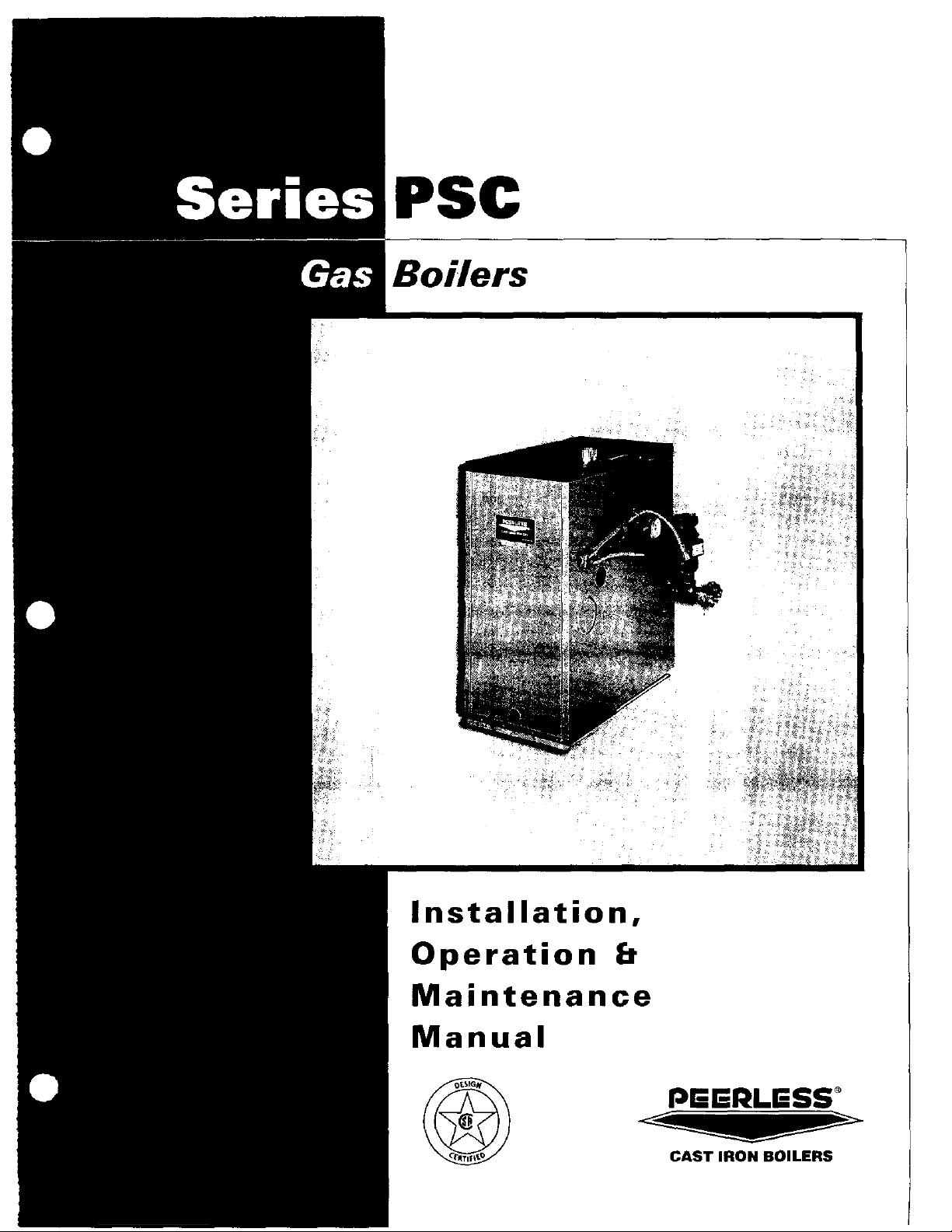
PSC
Installation,
Operation
Maintenance
Manual
PEERLESS °
CAST IRON BOILERS
Page 2
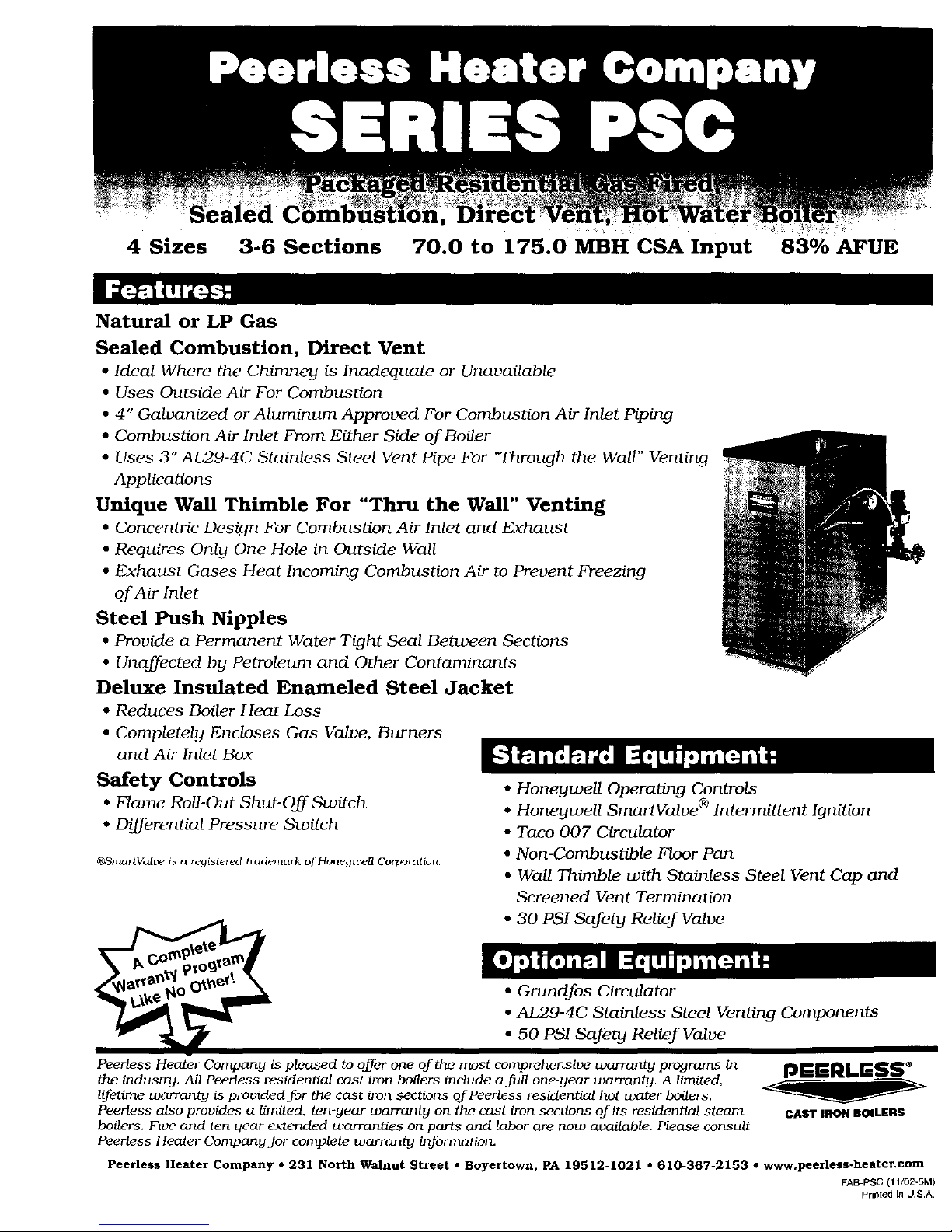
4 Sizes 3-6 Sections
70.0 to 175.0 MBH CSA Input 83% AFUE
Natural or LP Gas
Sealed Combustion, Direct Vent
• Ideal Where the Chimney is Inadequate or Unavailable
• Uses Outside Air For Combustion
• 4" Galvanized or Aluminum Approved For Combustion Air Inlet Piping
• Combustion Air Inlet From Either Side of Boiler
• Uses 3" AL29-4C Stainless Steel Vent Pipe For "Through the Wall" Venting
Applications
Unique Wall Thimble For "Thru the Wall" Venting
• Concentric Design For Combustion Air Inlet and Exhaust
• Requires Only One Hole in Outside Wall
• Exhaust Gases Heat Incoming Combustion Air to Prevent Freezing
of Air Inlet
Steel Push Nipples
• Provide a Permanent Water Tight Seal Between Sections
• Unaffected by Petroleum and Other Contaminants
Deluxe Insulated Enameled Steel Jacket
• Reduces Boiler Heat Loss
• Completely Encloses Gas Valve, Burners
and Air Inlet Box
Safety Controls
• Flame Roll-Out Shut-OffSwitch
• Differential Pressure Switch
_SraartValve is a registered trademark oj'Honeywell Corporation.
• Honeywell Operating Controls
• Honeywell SmortValve ® Intermittent Ignition
• Taco 007 Circulator
• Non-Combustible Floor Pan
• Wall Thimble with Stainless Steel Vent Cap and
Screened Vent Termination
• 30 PSI Safety Relief Valve
• Grundfos Circulator
• AL29-4C Stainless Steel Venting Components
• 50 PSI Safety Relief Valve
Peerless Heater Company is pleased to offer one of the most comprehensive warranty pro_lrams in
the industry. All Peerless residential cast iron boilers include a full one-year warranty. A limited,
lifetime warranty is provided for tile cast iron sectior_s of Peerless residential hot water boilers.
Peerless also provides a limitc, d, ten-year warranty on the cast iron sections of its residential steam
boilers. Five and ten year extended warranties on parts and labor are now available. Please consult
Peerless Heater CorrqgoJly for complete warranty information.
pGERLESS ®
CAST IRON BOILERS
Peerless Heater Company • 231 North Walnut Street • Boyertow_, PA I9512-1021 • 610-367-2153 • www.peerless-heater.com
FAB PSC (11/02-5M)
Printed in U.S.A
Page 3
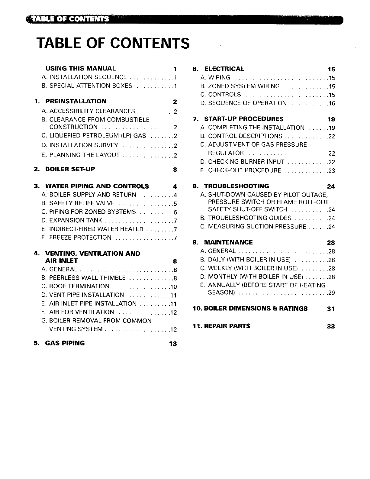
TABLE OF CONTENTS
1°
2,
3.
4.
USING THIS MANUAL 1
A. INSTALLATION SEQUENCE ............. 1
B. SPECIAL ATTENTION BOXES ........... 1
PREINSTALLATION 2
A. ACCESSIBILITY CLEARANCES .......... 2
B. CLEARANCE FROM COMBUSTIBLE
CONSTRUCTION ..................... 2
C. LIQUEFIED PETROLEUM (LP) GAS ....... 2
D. INSTALLATION SURVEY ............... 2
E. PLANNING THE LAYOUT ............... 2
BOILER SET-UP 3
WATER PIPING AND CONTROLS 4
A. BOILER SUPPLY AND RETURN .......... 4
B. SAFETY RELIEF VALVE ................ 5
C. PIPING FOR ZONED SYSTEMS .......... 6
D. EXPANSION TANK .................... 7
E. INDIRECT-FIRED WATER HEATER ........ 7
E FREEZE PROTECTION ................. 7
VENTING, VENTILATION AND
AIR INLET 8
A. GENERAL ........................... 8
B. PEERLESS WALL THIMBLE ............. 8
C. ROOF TERMINATION ................. 10
D. VENT PIPE INSTALLATION ............ 11
E. AIR INLET PIPE INSTALLATION ......... 11
E AIR FOR VENTILATION ............... 12
G. BOILER REMOVAL FROM COMMON
VENTING SYSTEM ................... 12
6. ELECTRICAL 15
A. WIRING ........................... 15
B. ZONED SYSTEM WIRING ............. 15
C. CONTROLS ........................ 15
D. SEQUENCE OF OPERATION ........... 16
7. START-UP PROCEDURES 19
A. COMPLETING THE INSTALLATION ...... 19
B. CONTROL DESCRIPTIONS ............. 22
C. ADJUSTMENT OF GAS PRESSURE
REGULATOR ....................... 22
D. CHECKING BURNER INPUT ............ 22
E. CHECK-OUT PROCEDURE ............. 23
8. TROUBLESHOOTING 24
A. SHUT-DOWN CAUSED BY PILOT OUTAGE,
PRESSURE SWITCH OR FLAME ROLL-OUT
SAFETY SHUT-OFF SWITCH ........... 24
B. TROUBLESHOOTING GUIDES .......... 24
C. MEASURING SUCTION PRESSURE ...... 24
9. MAINTENANCE 28
A. GENERAL .......................... 28
B. DAILY (WITH BOILER IN USE) .......... 28
C. WEEKLY (WITH BOILER IN USE) ........ 28
D. MONTHLY (WITH BOILER IN USE) ....... 28
E. ANNUALLY (BEFORE START OF HEATING
SEASON) .......................... 29
10. BOILER DIMENSIONS 8 RATINGS 31
11. REPAIR PARTS
33
5. GAS PIPING 13
Page 4
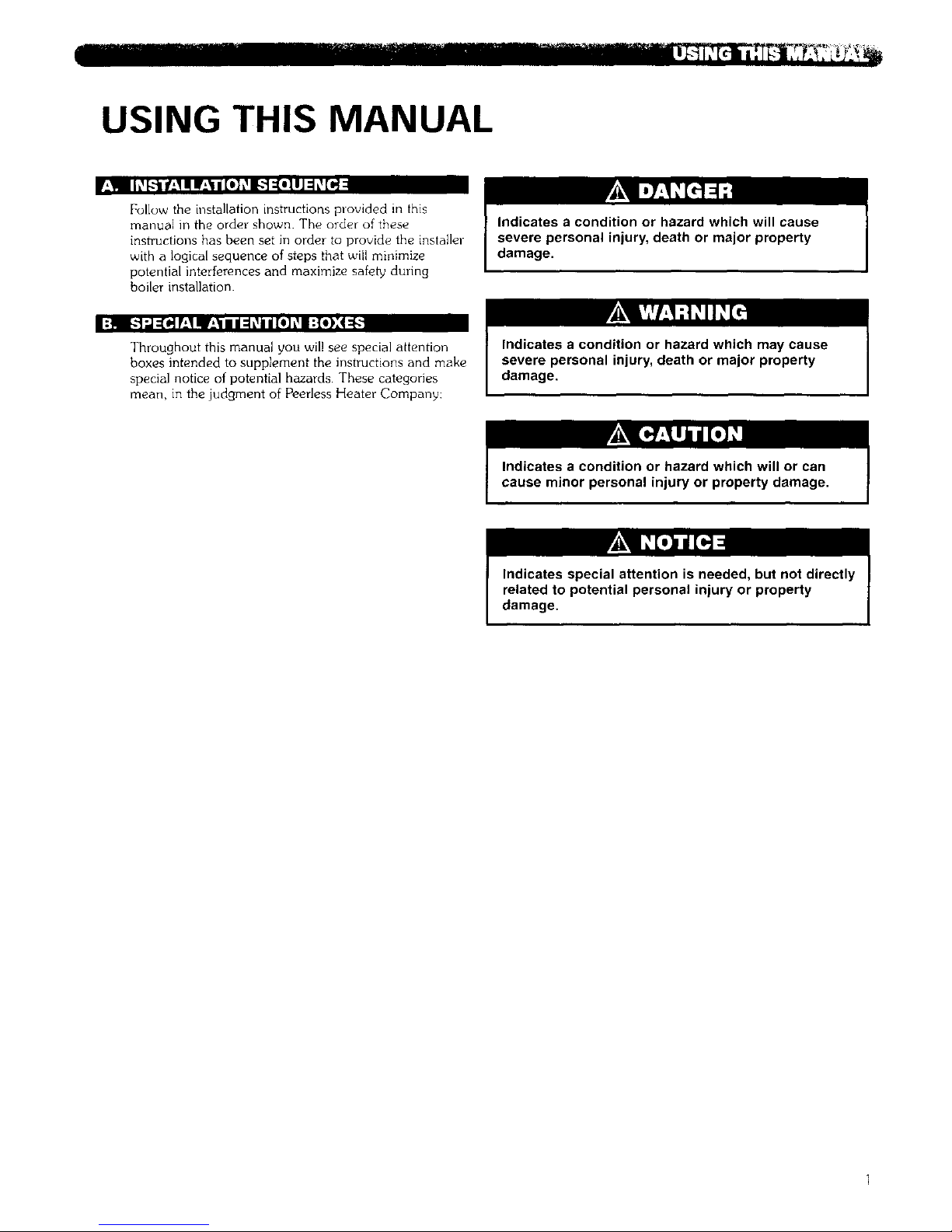
USING THIS MANUAL
f_'! I h_[.:'_lf-'_1e If-'_l/[o]_,_l_.:-]::[o].l]::h,_[I,,J
Follow the installation instructions provided in this
manual in the order shown. The order of these
instructions has been set in order to provide the installer
with a logical sequence of steps that will minimize
potential interferences and maximize sMet_ during
boiler installation.
Indicates a condition or hazard which will cause
severe personal injury, death or major property
damage.
I:_q [_'J:=[_F-*_qlllr_._lllll:lL_all[e)L_I:{o),:4_
Throughout this manual you wil! see special attention
boxes intended to supplement the instructions and make
special notice of potential hazards These categories
mean, in the judgment of Peerless Heater Company:
Indicates a condition or hazard which may cause
severe personal injury, death or major property
damage.
Indicates a condition or hazard which will or can
cause minor personal injury or property damage,
Indicates special attention is needed, but not directly
related to potential personal injury or property
damage.
Page 5
1. PREINSTALLATION
Read carefully study th_se instructions before beginning \vork
This boiler must be installed by a qualified contractor
The boiler warranty can be voided if the boiler is not instal}ed, maintained and serviced correctly.
The equipment must be installed in accordance with those installation requirements of the authority having
jurisdiction or, in the absence of such requirements, to the current edition of the National Fuel Gas Code, ANSI
Z223. f/NFPA 54.
Where required by the authority having jurisdiction, the installation must conform to American Society of Mechanical
Engineers Safety Code for Controls and Safety Devices for Automatically Fired Boilers, ANSI/ASME CSD-1.
Install boiler not less than 24" between the left side, top.
and front of the boiler and adjacent wall or other
appliance, when access is required for servicing.
The design of this boiler is certified for closet installation
with the following clearances:
1. 6" between right side, front and combustible
cotlstruction
2. ]2" between top of jacket and combustible
construction
3. 1"" between left side, rear and combustible
construction,
4. 2" between vent pipe and combustible construction.
5. 0" between wall thimble and combustible
construction
6. This boiler is design certified for use on combustible
flooring
K4 ! [ollJ _ dI _ m]'] :3 i -"{o]! :ill _Vllll_[¢'F;_
The following LP requirements from the Uniform
Mechanical Code, section 304.6, may be in effect in
your geographic area:
"Liquefied petToleum gas-burning appliances shall
not be installed in a pit. basement or similar location
where heavier-than air gas might collect. Appliances
so fueled shall not be installed in an above-grade
under-floor space or basement unless such location
is provided with an approved means for removal of
unburned gas."
D]q I h__.'t If_,1II If_*_lII[*] _,_H-'l IJ ;iLv__i"
For new and existing installations, a Water Installation
Survey is available from Peerless Heater Company. The
survey will provide information on how a hot water
boiler works with your specific system and will provide
an overview of hot water system operation in general.
You can also use this survey to locate system problems
which will have to be corrected. To obtain copies of the
Water Installation Survey, contact your Peerless
representative.
I=m I:Jar,..1b,'_h,'llh.'_[_ili:l:l IIr_,V='ollj
Do not install this boiler on carpeting. Boiler
installation on carpeting is a fire hazard. Install this
boiler on non-combustible flooring or use a
combustible floor pan to install this boiler on other
non-carpeted flooring.
Prepare sketches and notes of the layout to minimize the
possibility of interferences with new or existing
equipment, piping, venting and wiring. Review
Limitations on vent pipe, vent terminal, and air inlet pipe
locations and ventilation air requirements in Section 4.
Liquefied Petroleum (LP) is heavier than air and may
collect or "pool" in a low area in the event of a leak
from defective equipment. This gas may then ignite,
resulting in a fire or explosion. See the instructions
below.
Page 6
2. BOILER SET-UP
1 Provide a sound, level foundation Locate boiler as
near to the chimney or outside wal! as possible and
centralized with respect to the heating system
2 Locate boiler in front of installation position before
removing crate
4 Separate the wood shipping pallet ff()m the boiler
base by removing two (2) hold down bolts at each
end of the boiler base
5. Move boiler into final position.
Page 7

3. WATER PIPING AND CONTROLS
r,_! I:{e] I I! =i:!_'tl J ;j "Jk'm,__ _I w]l ; I =ilI[I J;1h_
]. Size the supply and return to suit the system. A
typical piping arrangement is shown in Figure i.
Refer also to the Hydronics Institute Residential
Hydronic Heating Guide 2000 and the Peerless
Water Survey for additional guidance during water
piping installation.
2 Return Piping:
a. For boilers equipped with a factory-mounted
circulator, pipe the return to the inlet connection
of the circulator.
b For boilers equipped with a separate, unmounted
circulator, pipe the outlet connection of the
circulator to a tee, provided with a drain valve, at
the 1-1/4 NPT return tapping near the bottom of
the right section Pipe the return to the inlet
connection of the circulator
3
4.
5.
Supply Piping:
a Pipe the supply to the I I 2 NPT supply tapping
at the top of the boiler.
b Provide clearance to venting system
(see Section 4)
When system return water temperature will be below
130°F, pipe the boiler with a bypass arrangement to
blend the system return and hot supply to obtain at
least 130°F entering the boiler. For more information
on bypass piping, consult the Peerless Water Survey
If desired, install the circulator in the alternate
location shown in Figure I. Consult the Peerless
Water Survey for more information on circulator
location
AIR VENT_
AIR ELIMINATOR _
-- SAFETY
RELIEF
VALVE
)_-ALTERNATE
CIRCULATOR
LOCATION
SUPPLY
COLD
WA1ER
NLL
SHUTOFF
VALVE VALVE" REDUCING VALVE
VALVE
_-EXPANStON TANK
0
o
©
TO DRAIN
RE_JRN
CIRCULATOR
DRAIN
VALVE
Figure 1: Supply and Return Piping
Page 8
6. Install this boiler so that the gas ignition system
components are protected from water (dripping,
spraying, etc.) during appliance operation and
service (circulator replacement, condensate trap,
control replacements, etc.).
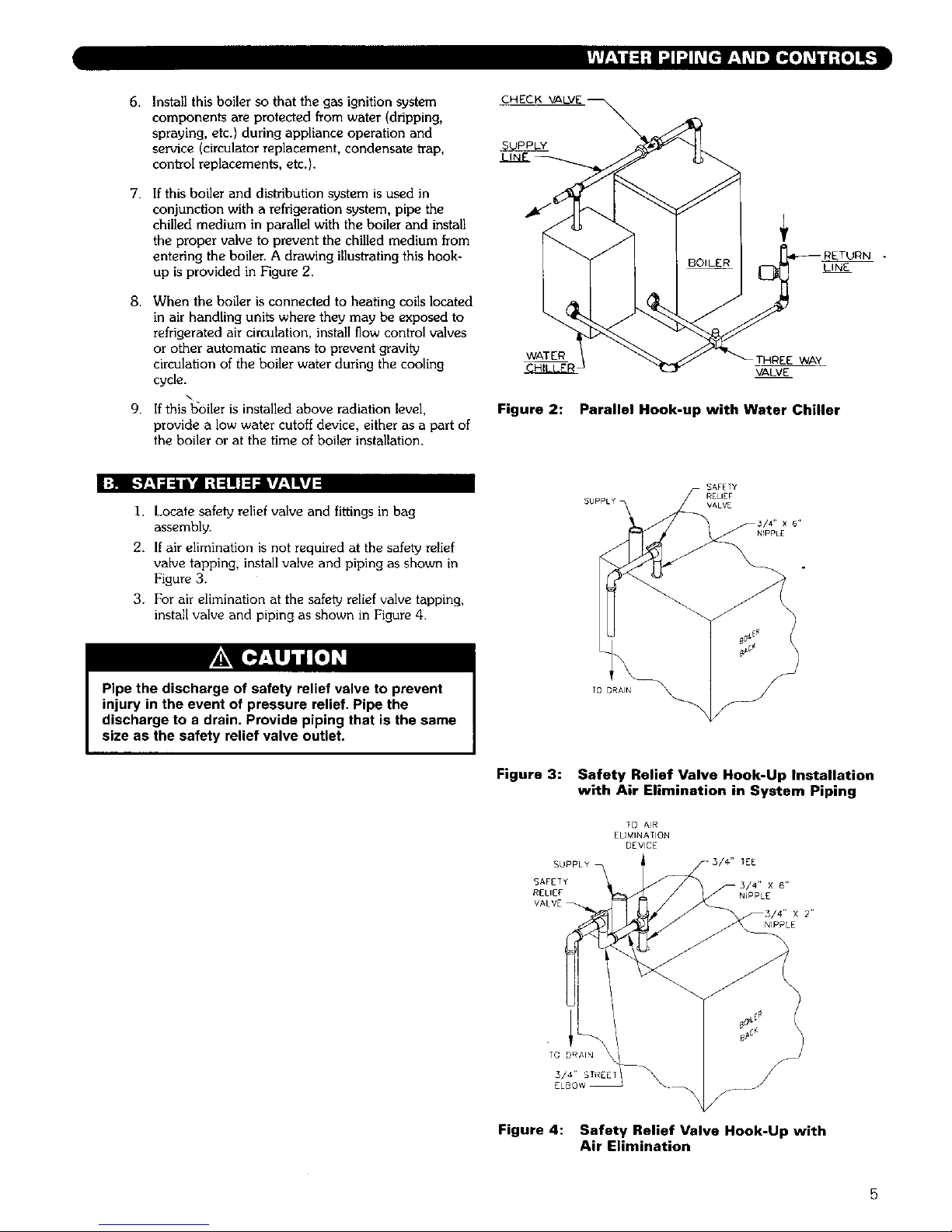
7. If this boiler and distribution system is used in
conjunction with a refrigeration system, pipe the
chilled medium in parallel with the boiler and install
the proper valve to prevent the chilled medium from
entering the boiler. A drawing illust_ating this hook-
up is provided in Figure 2.
8. When the boiler is connected to heating coils located
in air handling units where they may be exposed to
refrigerated air circulation, install flow control valves
or other automatic means to prevent gravity
circulation of the boiler water during the cooling
cycle.
9. If this boiler is installed above radiation level,
provide a low water cutoff device, either as a part of
the boiler or at the time of boiler installation.
WATER
THREE WAY
VALVE
Figure 2: Parallel Hook-up with Water Chiller
I:t k"l'_l:lii'l ;tqlllir/_'lliVi
1. Locate safety relief valve and fittings in bag
assembly.
2. If air elimination is not required at the safety relief
valve tapping, install valve and piping as shown in
Figure 3.
3. For air elimination at the safety relief valve tapping,
install valve and piping as shown in Figure 4.
Pipe the discharge of safety relief valve to prevent
injury in the event of pressure relief. Pipe the
discharge to a drain. Provide piping that is the same
size as the safety relief valve outlet.
SAFETY
RELIEF
SUPPLY VALV E
NIPPLE
Figure 3: Safety Relief Valve Hook-Up Installation
with Air Elimination in System Piping
TO AIR
ELIMINATION
DEVICE
SUPPLY I-3/4" TEE
SAFETY r5/4" X 6"
RELIEF NIPPLE
VALVE_-._I_
_3/4" x 2"
NIPPLE
Figure 4: Safety Relief Valve Hook-Up with
Air Elimination
Page 9
[eJll I",11".11_.'1[€'li =[e]; _),,[e] L_I =i Ii]k"L'4.."]ili =iLvj[..
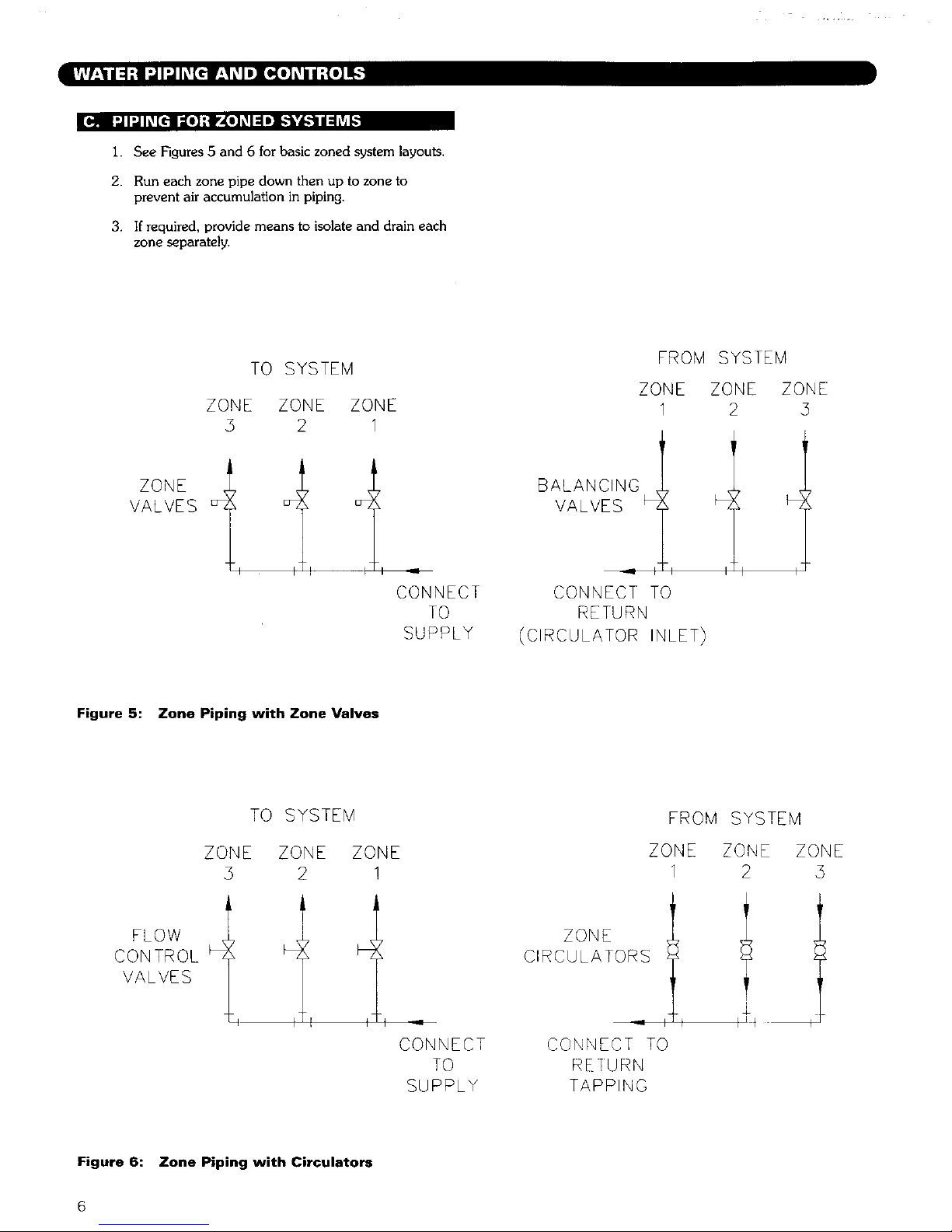
1. See Figures 5 and 6 for basic zoned system layouts.
2. Run each zone pipe down then up to zone to
prevent air accumulation in piping.
3. If required, provide means to isolate and drain each
zone separately.
TO SYSTEM
ZONE ZONE ZONE
5 2 1
I
ZONE
VALVES _z
I
_Z
J
_Z
CONNECT
TO
SUPPLY
FROM SYSTEM
ZONE ZONE ZONE
1 2 5
BALANCING
VALVES
CONNECT TO
RETURN
(CIRCULATOR INLET)
tl
Figure 5: Zone Piping with Zone Valves
TO SYSTEM
ZONE ZONE ZONE
5 2 !
FROM SYSTEM
ZONE ZONE ZONE
1 2 5
FLOW
CONTROL
VALVES
! I .11
CONNECT
TO
SUPPLY
ZONE
CONNECT TO
TAPPING
±
Figure 6: Zone Piping with Circulators
6
Page 10
;I;t :1_11 "J:[elll :[_ | {o] L_
II]l I :F:4:L'I0F_"]{e]L_IbV:I_1:
1. Consult the tank manufacturer's instructions for
specific information relating to tank installation Size
the expansion tank for the required system volume
and capacity See Table c) in Section 10 for bof]¢,_
water capacity
2. Expansion tanks are available with built in fill valves
and check valves for reducing supply water pressure
and maintaining minimum system pressure. Check
the design features of the tank and provide valves as
necessary.
Refer back to Figure i for typical expansion tank piping.
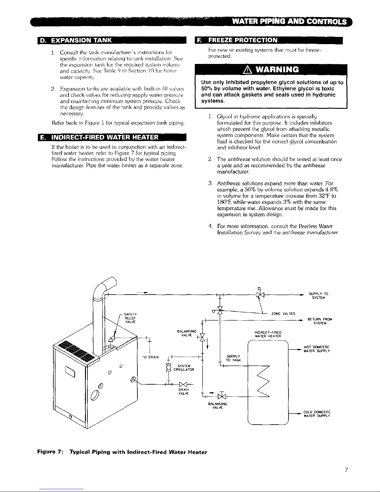
:1! I01_11;t:[q II: I1t:1eir_Jf_'li :1;t I11!:II / :1;
If the boiler is to be used in conjunction with an indirect-
fired water heater, refer to Figure 7 for typical piping
Follow the instructions provided by the water heater
manufacturer. Pipe the water heater as a separate zone.
For new or existing systems that must be freeze-
protected:
2.
3.
4+
Glycol in hydronic applications is specially
formulated for this purpose. It includes inhibitors
which prevent the glvcol from attacking metallic
system components Make certain that the system
fluid is checked for the correct gtycol concentration
and inhibitor level.
The antifreeze solution should be tested at least once
a year and as recommended by the antifreeze
manufacturer.
Antifreeze solutions expand more than water. For
example, a 80% by volume solution expands 4.8%
in volume for a temperature increase from 32°F to
180°F, while water expands 3% with the same
temperature rise. Allowance must be made for this
expansion in system design.
For more information, consult the Peerless Water
Installation Survey and the antifreeze manufacturer
SAFETy
RELIEF
VALVE
TO DRAIN
BALANCING
VALVE
O SYSTEM
{_ O CIRCULATOR
©
DRAIN
VALV [
ZONE VALVES
INDIRECT-FIRED
WATER HEAER
SUPPLy
TO TANK
i /
BALANONG
VALVE
SUPPLY TO
SYSTEM
q RETURN FROM
SYSTEM
HOT DOMESTIC
_WATER SUPPLy
COLD DOMESTIC
WAIER SUPPLY
Figure 7: Typical Piping with Indirect-Fired Water Heater
Page 11
4. VENTING
Install vent system in accordance with Part 7, Venting of
Equipment, National Fuel Gas Code, ANSI Z223,1/NFPA
54 or applicable provisions of the local building codes.
This vent system will operate with a positive
pressure in the vent pipe. Do not connect vent
connectors serving appliances vented by natural
draft into any portion of mechanical draft systems
operating under positive pressure.
Flue gases will condense as they exit the vent
termination. This condensate can freeze on exterior
building surfaces which may cause discoloration of
these surfaces.
1 Determine vent cap (terminal) location.
a Must be within the maximum and minimum vent
and air intake lengths shown in Tables 1 and 2.
b Maximum wall thickness for the 1%1/2" long
Peerless Wall Thimble (standard)is I 1-I/2".
Maximum wall thickness for the optional 28"
long thimble is 20".
C
Provide 2" clearance between vent pipe and
combustible construction No clearance is
required between Thimble and combustible
construction
d. Provide 3 feet clearance above any forced air
inlet within I0 feet.
e. Provide 1 foot clearance below. 1 foot beside, or
1 foot above any door, window, or gravity air
inlet into any building
Provide 1 foot clearance between bottom of vent
terminal and ground level and normal snow
lines.
g.
h.
Provide 4 feet horizontal clearance from. and in
no case above or below, unless a 4 foot
horizontal distance is maintained, from electric
meters, gas meters, regulators and relief
equipment.
Do not locate vent terminal over public walkways
where condensate could createa nuisance or
hazard.
i.
j.
When adjacent to a public walkway, locate vent
terminal at least 7 feet above grade
Do not locate directly under roof overhangs to
prevent icicles from forming
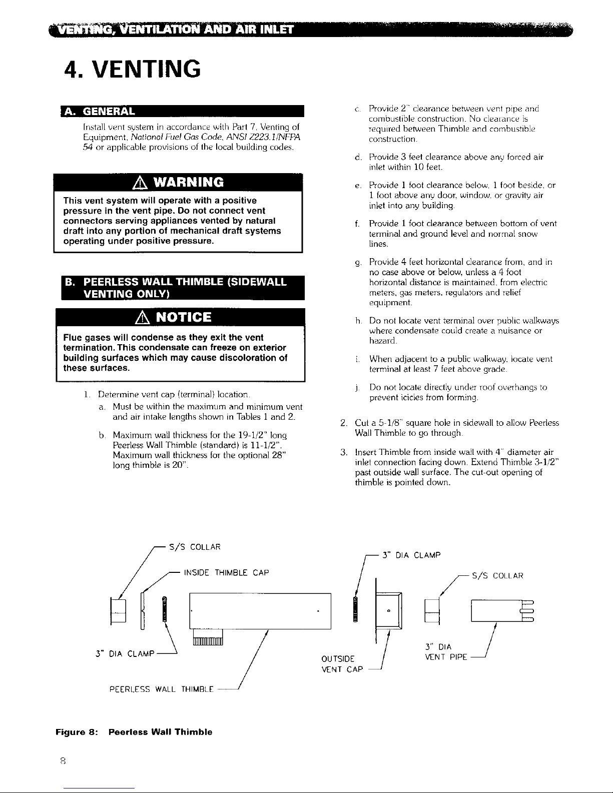
2. Cut a 5-]/8" square hole in sidewall to allow Peerless
Wall Thimble to go through
3. Insert Thimble from inside wall with 4" diameter air
inlet connection facing down. Extend Thimble 3-I/2"
past outside wall surface. The cut-out opening of
thimble is pointed down.
COLLAR
INSIDE THIMBLE CAP
/
3" DIA CLAMP /
PEERLESS WALL THIMBLE
3" DIA CLAMP
!
OUTSIDE 3" DIA
VENT PIPE
VENT CAP
Figure 8: Peerless Wall Thimble
Page 12
4.
5.
6.
7.
8.
Use a nqinimum 2-1/2" foot piece of 3" diameter
AL29 4C stainless steel vent pipe fol insertion
through Wall Thimble. See Vvnt Pipe section below
for vent pipe requirements
Slide Stainless Steei Collar over vent pipe and slide
3" diameter hose clamp and collar to vent pipe
Insert pipe with collar through Outside Vent Cap and
slide 3" diameter hose clamp and collar to vent pipe.
Leave at least 2" of vent pipe protruding beyond
face of Vent Cap and secure hose clamp and collar
to vent pipe.
Place Outside Vent Cap over Wall Thimble with air
openings in Vent Cap facing down. Secure Cap to
Thimble with #10 sheet metal screws
9. Place 3' diameter hose clamp over pipe protruding
through inside of Wall Thimble
10. Place Inside Thimble Cap and Collar onto Wall
Thimble. Access hose clamp through 4" diameter
collar on bottom of Thimble and secure hose clamp
over collar and vent pipe as per step 7 above.
1 1 Secure Inside Thimble cap to Wall Thimble with # 10
screws Seal Thimble Cap perimeter with silicone
12 Seal all openings between Wall and Thimble and
around the 3- diameter stainless steel vent pipe that
protrudes through hlside and outside of Wall
Thimble
13 Add any bracing that may be needed to support Wall
Thimble on inside of wall structure.
14, Secure Outside Vent Cap to exterior wall with four
#]0 sheet metal screws provided.
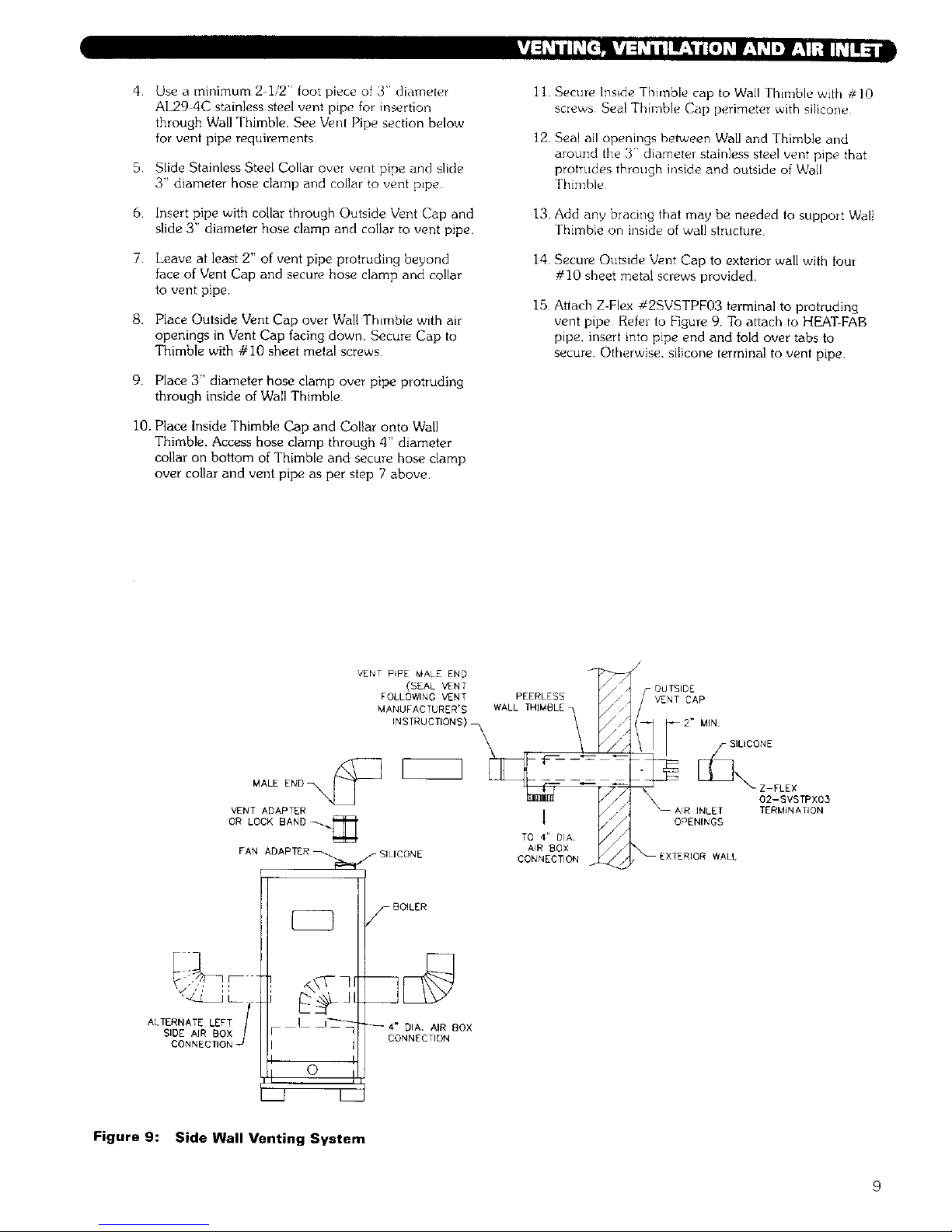
15 Attach Z-Flex #2SVSTPF03 terminal to protruding
vent pipe Refer to Figure 9. To attach to HEATFAB
pipe. insert into pipe end and fold over tabs to
secure Otherwise, silicone terminal to vent pipe.
VENT PIPE MALE END
(SEAL VENT _///
FOLLOWING VENT PEERLESS// /
MANUFACTURER'S WALL THIMBLE /, r_/
INSTRUCTIONS) _ _/
\
VEN
OR
_. TO 4" DIA I_j
FAN ADAPTER f SILICONE AIR BOX
CONNECTION _//'
/
OUTSIDE
2 _ MIN
f SILICONE
02-SVSTPXOS
AIR iNLET TERMIN ATION
OPENINGS
_EXTERIOR WALL
• ,,' 11
L
ALTERNATE LEFT /SIDE AIR BOX
CONNECTION
_- BOILER
--4" DIA AIR 80X
CONNECTION
Figure 9: Side Wall Venting System
9
Page 13

1.
2.
3.
4.
5.
Vent pipe and air inlet terminations must be within
the maximum and minimum vent and air intake
lengths shown in Tables 1 and 2.
Vent pipe and air inlet pipe must terminate 12"
above expected snow lines Vent pipe must be a
minimum ]2" above and 12" horizontally from air
inlet pipe. See Figure 10
Attach a vent manufacturer's listed rain cap to both
the vent pipe and air inlet pipe.
Provide 2" clearance between vent pipe and
combustible construction. No clearance is required
between air inlet pipe and combustible construction
See vertical venting section in vent manufacturer's
instructions for recommendations for penetration
through roof.
Table 1 :
*Equivalent Length of 3" Diameter
Stainless Steel Vent Pipe
Boiler Model Minimum Vent Length _4aximum Vent Length
PSC-03 S feet 52 feet
PSC 04 8 feet 52 feet
PSC 05 8 feet 45 feet
PSC 06 8 feet 45 feet
Table 2:
*Equivalent Length of 4" Diameter
Aluminum/Galvanized Air Inlet Pipe
Boiler Model Minimum Length Maximum Length
PSC 03 12 feet 70 feet
PSC 04 12 feet 70 feet
PSC-05 12 feet 63 feet
PSC-06 12 fPet 63 feet
*Each 90 ° elbow equals 5 feet of equivalent length.
ATTACH VENT
} MANUFAC]URER S
12" LISTLD RAIN CAP
MIN
1
12"
MIN
3" DIA
VENT PIF
2" MIN
CLEARANCE
(_ FLOOR
FrRESTOP J
SLOPE UP 1/4"
PER FOOT"
HORIZONTAL
DRAIN
FA" []........_
ADAp]ER
_NT PIPE
AZAI_ TLR OR
BOFLERI_ LOCK BAND
ALTERNATE
LEFT SPDE
AIR INLET
PlPE
LOCATIO
_NLET PIPE
(USE GALVANIZED PIPE OR 'O' VENT
W4EN PENE_A]]NG FLOOR & ROOF)
DRAIN TRAP
(FORM 3" DIA
LOOP)
Figure 10: Vertical Venting System
10
Page 14

Ill mY4 =lb.'Hai I:JI'.,l::i iL__"]aW-'IHIar-"aai[o] K_
1.
2.
3.
r_,qI:il I_I al::liaid".JI:,J_ IIk_[,.-'11ir_,1nar_,'aiI[,] _
4,
For minimum and maximum vent pipe lengths see
Table 1
Use only 3" diameter Heat Fab Saf-T Vent, Z-Flex
Z V_nt, ProTech FasNSeaL or Flex L Star-34 Type
AL2.9-4C stainless steel vent pipe and fittings for
venting of flue gases from the boiler.
Connect vent pipe to boiler by spreading a I/4" bead
of high-temp GE 106 silicone or Silicones Unlimited
$45005 Red around the fan adapter. Attach proper
vent adapter to fan adapter (not applicable, Z-Flex)
Z-Flex vent pipe/fiRing connects directly to fan
adapter, secure to fan adapter using Z-Flex lock band.
See Figure 11.
Attach remaining pipe and fittings per each
manufacturer's vent instructions. Use only the silicone
recommended by vent pipe manufacturers. Maintain
proper clearance to combustible construction - see
Section 1, Preinstallation.
5. a,
b,
Side Wall Venting Only - Horizontal lengths of
the vent pipe shall slope down not less than 1/4"
per foot from the boiler to the vent terminal. If
vent pipe does slope back toward boiler, a
horizontal drain is required as described in 5B and
Figure 10.
Vertical Venting Only - A horizontal drain tee is
required. Slope horizontal lengths ._ not less
than I/4" per foot from the boiler to the vent
terminal. Install drain tee as shown in Figure I0.
Use silicone hose and form a 3" diameter loop
trap with a water seal. Pipe to drain per
local code.
6.
Support horizontal l_,ngths of the vent system to
prevent sagging by use of metal strapping or
equivalent means. Locate supports at not more than
four (4) foot intervals
Vertical Venting Only - If there is no solid anchor
point in the system below the roof for supporting
vertical sections of the vent pipe fie Firestop
Support, etc.), a special vent support system will be
required. See vent manufacturer's instructions for
additional information
1.
2.
3.
4.
5.
6.
7.
For maximum air inlet pipe lengths see Table 2
Use only 4" diameter galvanized pipe or 4" diameter
flexible aluminum vent for supplying combustion air to
boiler inlet air box.
Boiler connection can be from either right or left side
of boiler jacket Determine which jacket side air inlet
piping is to be routed and remove the 4-1/2" jacket
knock out.
Attach a 4" diameter 90 degree elbow to top of air
box and connect air inlet piping.
Support air inlet piping using the same methods and
requirements as shown in the previous section for vent
pipe support.
Seal all connections using silicone.
To prevent condensation from forming on exposed
portions of Wall Thimble and 4" diameter air inlet
piping, wrap exposed aleas with insulation.
Z-FLEX
Z-VENT
MALE
Z-FLEX
Z VENT
LOCKING
BAND
SVSLBXO3
HEAT-FAB
SAF-T VENT
PIPE,
MALE END
HEAT-FAB
_ AF-T VENT
7301AMTK
VENT ADAPTER
PROTECH
FABNSEAL
VENT PIPE
MALE END'
FLEX-L
- STAR-34
VENT PIPE
MALE END'
PROTECH FLEX-L
I FASNSEAL _ STAR-54
FSA-PSC/DE 3 SRAPPA3
VENT ADAPTER VENT ADAPTER
1/4" BEAD 1/4" BEAD 1/4" BEAD !/4" BEAD
LREEB E LPER E B
AOA TEBAOAPTERAOA ' R ABA TER
Figure 1 1: Vent Connection to Boiler
11
Page 15

r,_Ii;ti;[,]--tkvA:ik_/ il Ir!_lII[*] f
1.
2.
Provide air openings for adequate ventilation in
accordance with Section 5.3 Air for Combustion
and Ventilation, of the National F_el Gas Code,
ANSI Z223 I NFPA 54. ol applicable provisions of
the local building codes Ventilation is required to
prevent overheating of the controls which greatly
reduces the life of the controls Air inlet piping
provides only combustion air to the boiler See
Section D for Air Inlet Piping requirements
Definition:
Unconfined Space: a space whose volume is not
less than fifty (50) cubic feet per I000 Btu/hr of the
total input rating of all appliances installed in that
space. Rooms communicating directly with the space
in which the appliances are installed, through
openings not furnished with doors, are considered
part of the unconfined space
3.
Appliances Located in Unconfined Spaces:
For installations in unconfined spaces, the supply of
air for ventilation can usually be considered
adequate.
Appliances Located in Confined Spaces:
Provide two permanent openings communicating
directly with an additional room or rooms of sufficient
volume so that the combined volume of all spaces meets
the criteria for an unconfined space Use the total input
of all gas utilization equipment installed in the combined
space in making this determination
Size each opening with a minimum free area of one
square inch per I000 Btu/hr. of the total rating of all gas
utilization equipment in the confined space, but not less
than 100 square inches Begin with one opening 12
inches from the top, and begin the other opening within
12 inches of the bottom of the enclosure See Figure 12.
Provide air openings with minimum dimensions not less
than three (3) inches.
TWO AIR OPENINGS:
Minimum
Free Area Each -
1 in 2per 1000 Btuh
at Least 100 in 2
BOILER
12" max
3" min
,L
I 3" min
12" max
Figure 12: Air Openings
At the time of removal of an existing boiler, follow these
steps with each appliance remaining connected to the
common venting system placed in operation, while the
other appliances remaining connected to the common
venting system are not in operation:
a Seal any unused openings in the common venting
system
b.
Visually inspect the venting system for proper size
and horizontal pitch and determine there is no
blockage or restriction, leakage, corrosion and other
deficiencies which could cause an unsafe condition.
C. Insofar as is practical, close all building doors and
windows and all doors between the space in which
the appliances remaining connected to the common
venting system are located and other spaces of the
building. Turn on any clothes dryers and any
appliance not connected to common venting system.
Turn on any exhaust fans. such as range hoods and
bathroom exhausts, so they will operate at maximum
speed. Do not operate a summer exhaust fan. Close
fireplace dampers.
d. Place in operation the appliance being inspected.
Follow the lighting instructions. Adjust thermostat so
appliance will operate continuously.
e.
Test for spillage at the draft hood relief opening after
5 minutes of main burner operation. Use the flame
of a match or candle, or smoke from a cigarette,
cigar, or pipe
After it has been determined that each appliance
remaining connected to the common venting system
properly vents when tested as outlined above, return
doors, windows, exhaust fans. fireplace dampers and
any other gas burning appliance to their previous
conditions of use.
g. Any improper operation of the common venting
system should be corrected so that the installation
conforms with the National Fuel Gas Code, ANSI
Z223.1/NFPA 54. When resizing any portion of the
common venting system, the common venting
system should be resized to approach minimum size
as determined using the appropriate tables in Part 11
of the National Fuel Gas Code, ANSI Z223.1/NFPA
54.
12
Page 16

--m
5. GAS PIPING
I Size and install the gas supply piping properly in
order to provide a supply of gas sufficient to meet
the maximum demand without undue loss of
pressure between the meter and the boile_
2 Determine the volume of gas to be provided to the
boiler in cubic feet per hour. To obtain this value,
divide the Btu per hour rating (on the boiler rating
plate) by the heating value of the gas in Btu per
cubic feet. Obtain the heating value of the gas from
the gas supplien As an alternative, use Table 3 or 4
on the next page to obtain the volume of gas to be
provided to the boilen
3 Use the value obtained above as the basis for piping
sizing. Size the gas piping in accordance with Table
5. Consult the National Fuel Gas Code for other
sizing options.
4. Locate the drop pipe adjacent to, but not in front of
the boilen
5.
6.
Install a sediment trap. See Figure 13. Locate a tee
in the drop pipe at same elevation as the gas inlet
connection to the boiler. Extend the drop pipe to a
pipe cap.
Install a ground joint union ahead of the gas control
assembly to permit servicing of the control. Some
local codes require an additional service valve when
using the combination gas controls. If your code
requires such a valve, a suggested location is shown
in Figure 13.
Use a pipe joint sealing compound that is resistant to
the action of liquefied petroleum gas. A non-resistant
compound may lose sealing ability in the presence of
this gas, resulting in a gas leak and fire or explosion
potential.
7. Check piping for leaks prior to placing the boiler in
operation.
Use an approved gas detector, a non-corrosive leak
detection fluid or other leak detection method. If
leaks are found, turn off all gas flow and repair as
necessa W,
I _ SERVICE
VALVE
_--_ JACKET
G.J. UNION
I _ SEDIMENT TRAP
_ FLOOR LINE
Figure 13: Gas Connection to Boiler
8, Disconnect the boiler and its individual shut off valve
from the gas supply piping system during any
pressure testing of that system at test pressure in
excess of 1/2 psig (3.5 kPa).
Do not subject the gas valve to more than 1/2 psi
pressure. Doing so may damage the valve.
Isolate the boiler from the gas supply piping system
by closing its individual service valve during any
pressure testing of the gas supply piping system at
test pressure equal to or less than 1/2 psig (35 kPa)
9. Minimum permissible supply pressure for purposes of
input adjustment (Inches Water Column):
Natura! Gas 5.0"
LP Gas l 1.0"
Maximum permissible supply pressure to the boiler
(Inches Water Column):
Natural Gas 13.5"
LP Gas 13.5"
When checking for leaks, do not use matches,
source of ignition. This can ignite a gas leak,
resulting in fire or explosion.
13
Page 17

KgFgKEc]
Table 3: Natural Gas
Input
Model (Cubic Ft!Hr)
PSC 03 70
PSC 04 105
PSC-05 140
PSC 06 175
Based on I000 Btu'Cubic Ft
Table 4: LP Gas
Input
Model (Cubic Ft!Hr)
PSC 03 28
PSC 04 42
PSC-05 56
PSC 06 70
Based on 2500 BtuiCubic Ft
Table 5: Pipe Capacity
Capacity of pipe of different diameters and lengths in cu. ft. per
hour with pressure drop of 03 in and specific gravity of 0 60
No allowance for an ordinary number of fittings is required
Pipe _14# I" 1I/4# 1112"
Length
Feet Pipe Pipe Pipe Pipe
10 278 520 1,050 1.600
20 190 350 730 I.I00
30 152 285 590 890
40 130 245 500 760
50 115 215 440 670
60 105 195 400 610
Multipliers to be used with the above table when the
specific gravity of the gas is other than 0.60:
Specific Gravity 05 055 0.60 065 0.70
Multiplier 110 1 04 100 0962 0926
14
Page 18

6. ELECTRICAL
Install all electrical wiring in accordance with the National Electrical Code and local requirements
This unit when installed must be electrically grounded in accordance with the requirements of the authority
having jurisdiction or, in the absence of such requirements, with the current edition of the National Electrical
Code, ANSI/NFPA 70.
r_'l WJl;i h_[€
]. See Figure 14 for location of wiring and controls.
Use Figure 15 to connect the boiler to a power
supply and to connect components to the boiler,
2. Connect the boiler by a separate, permanently live
electrical supply line with a fused switch.
3. Adjust the thermostat heat anticipator to 0.2 Amp.
:]1 W[e)L_I:IB]k"5"_"]ll:lL'JI_IiIil:|l_[C
See Figure 17 for typical wiring with zone valves. See
Figure 18 for typical wiring with zone circulators. When
wiring a zoned heating system, follow all applicable
codes, ordinances and regulations
I. For proper location of controls and accessories refer
to Figure 14
2. See the attached control sheets for specific details
regarding the installation of the various controls.
3. This boiler is supplied with safety devices in addition
to the limit. For a description of these devices and
how they work to ensure the safe operation of the
boiler, see Section 7.
4. If the circulator is mounted in the supply piping,
provide longer wiring harness as required.
Do not power zone valves directly from the boiler
transformer. Doing so will greatly reduce the life of
the transformer. Use a separate transformer sized to
handle the total of all zone valve electrical loads.
TO LINE VOLTAGE THERMOSTAT
POWER SUPPLY_
LIMIT CONTROL
PRESSURE
GAUGE
PRESSURE
SWITCH
GAS
ER RELAY
CENTER
RELAY
FLAME ROLLOUT SWITCH
Figure 14: Wiring, Controls and Safety Devices
15
Page 19

_)T[S:
l) ALL _IRINI_ MU_T COIdPLy U_T]@AP_IJ_ I_0_ _AN_ _#ID REQI3LAT_D{_
_, IT MUST _ r_':t_ClJ_ _1_ _E _ _.
_:_IL
P_MARY W
T
(PILOT
-- l_ov _I_NG _NG )
24V W_
Figure 15: Wiring and Connection Diagram
[)]II _ ::[.llJ ::10[_] : [el :lt]'] :_'_:_1i [ill _
1. Thermostat calls for heat, energizes R8285 Control
Relay (CR).
2. R8285 Control Relay (CR) energizes circulaton
3. Limit senses boiler water temperature. Prevents
boiler operation until water temperature falls
approximately 15°F below the cut-out temperature.
4. Limit energizes Fan and R4222 Isolation Relay (IR).
5. Negative pressure induced by fan switches Pressure
Switch, continuing power through c[osed R4222
contacts (IR 1) and flame roll-out switch.
6. Gas valve energizes.
a. Igniter on.
b. Pilot gas on, igniting pilot.
7 Pilot flame detected.
a. Igniter off.
b. Main gas on, igniting main burners.
Note: If pilot flame is not detected within 30 seconds,
the igniter is turned off for 30 seconds, and then turned
back on for another 30 seconds. If the pilot remains
undetected in this second ignition period, the igniter and
pilot are turned off for 5 minutes. The sequence then
resumes at Step 6a.
8. Call for heat ends.
a. Pilot and main gas off, extinguishing pilot and
main burners.
b. Fan and circulator off.
16
Page 20

START
TRIAL
FOR
IGNITION
MAIN
BURNER
OPERATION
I APPLY 24 VAC ITO APPLIANCE
LTBE°M°STATJ
CALLS FOR HEAT
"<
_r
I FLAME SIGNAL _ • WAlT FOR FLAME SIGNAL
DETECTED? I Y l TO DISAPPEAR
• PILOT VALVE/IGNITER
_NO REMAIN OFF
I NO
INTERNAL CHECK OKAY? I
I
J_YES
• PILOT VALVE OPENS
• IGNITER POWERED
PILOTLIGHTSAND FLAME NO •
I D RIN PILOT VALVE CLOSES
YES
• IGNITER OFF J
• MAIN VALVE OPENS
END
I LAME SIGNAL LOST?
I THERMOSTAT CALL FOR I
HEAT ENDS
• MAIN AND PILOT VALVES CLOSE
t
• MAIN AND PILOT VALVES CLOSE I
I
FLAME LOST MORE THAN I NO
B
FIVE TIMES IN ONE
p--
CALL FOR HEAT?
J IYESl
IGNITER WILL TURN OFF ABOUT 30 SECONDS INTO THE TRIAL FOR IGNITION,
IF THE PILOT FLAME HAS NOT LIT, IT WILL TURN BACK ON FOR THE FINAL
30 SECONDS OF THE 90 SECOND TRIAL FOR IGNITION. THE PILOT VALVE
WILL BE ENERGIZED DURING THE ENTIRE TRIAL FOR IGNITION. THIS IS
NORMAL OPERATION FOR THIS GAS IGNITION SYSTEM.
I IVE-MINUTE RETRY 1DELAY
Figure 16: Ignition System Operating Sequence
17
Page 21

©
irl
i,i
ill
- -- LOw VOLTAGE
-- LINE VOLTAGE
NOT_.__.._.
_L_I. WIRING MUST ¢OMpL=v With APPL=CABL[
CODE5, OR IIlNAI4_ S. AND R_GI_L.ATION5
Figure 17: Zone Wiring with Zone Valves
ZONE el ZONE _2
..... _=OW VOLTAGIE
-- LIN_. VO L TA(_j__
ALL WIRING MUST _OMI_y WITH APP_ICAi_[
CODE S, OROIIV, ANC_ S, A_D R_GL_- ATION_,
©
I
T
ZONEe_
Figure 18: Zone Wiring with Circulators
18
Page 22

7. START-UP PROCEDURES
r,.!! [_1,1 L51:l i :1ilk'_[_ i I I I:! IL'_I.-If_,l i I!_,t I I.] i_
2.
3.
4.
5.
6>
Confirm that all water, gas and electricity are
turned off.
Inspect the boiler combustion chamber for foreign
objects and remove if present,
Check physical condition of burners and pilot. Make
certain that there are no unusual bends or
perforations in the burners or pilot. Replace
components if necessary.
Verify that water piping, venting, gas piping and
electrical wiring and components are installed
properly. Refer back to previous sections of these
instructions as well as equipment manufadurer's
instructions as necessary.
Fill the boiler and system with water, making certain
to vent all air from all points in the system. To check
water level in the system, open and close each vent
in the system. Water should exit from each vent
when it is opened.
The pressure reducing valve on the fill line will
typically allow the system to be filled and pressurized
to 12 psi. Consult the valve and expansion tank
manufacturer for more specific information.
7 Check joints and fittings throughout the system for
leaks. If leaks are found, drain the system and repair
as required
8. Connect a manometer to the I/8" npt inlet pressure
tap on the gas valve. See Figure 20.
9.
Confirm that the gas supply pressure to the boiler is
above the minimum and below the maximum values
for the gas being used. See the end of Section 5 for
these values. If a supply pressure check is required,
isolate the boiler and gas valve before performing
the pressure check. If the supply pressure is too high
or too low, contact the gas supplier.
10. Turn on electricity and gas to boiler
11, Light the boiler by following the Lighting/Operating
Instructions label mounted to the jacket panel. The
initial ignition may require several tries as the piping
is purged of air.
12. Use the sequence description and Figure 16 in
Section 6 (Electrical) to follow light-off and shutdown
sequences and to assist in diagnosing problems. If
the boiler does not function properly, consult Section
8. Troubleshooting.
19
Page 23

/- STEEL
l A"- 7 !BURNER
E
_X _- MANIFOLD
A_" _-TEST TAPPING
VALVE
PILOT TUBING
SECTION A-A
Figure 19: Gas Valve, Manifold and Burner Assembly - Intermittent Ignition
INLET
GAS PRESSURE REOULATOR
ADJUSTMENT SCREW
(UNDER CAP SCREW)
PRESSURE
TAP _
,NLET,j@(@_z
GAS 7
CONTROL /
SWITCH !
OUTLET
PRESSURE
TAP
ADJUSTMENT
Figure 20: Valve Tapping and Adjustment Screw Locations
2O
Page 24

FOR YOUR SAFETY READ BEFORE OPERATING
A.
I WARNING: If you do not follow these instructions exactly, a fire or explosion may result I
i
causing property damage, personal injury, or loss of life.
I
This appliance is equipped with an ignition device
which automatically lights the pilot. Do n_ot try to
light the pilot by hand
• If you cannot reach your gas supplier, call the fire
department
B. BEFORE OPERATING smell all around the
appliance area for gas Be sure to smell next to the
floor because some gas is heavier than air and will
settle on the floor.
WHAT TO DO OF YOU SMELL GAS
• Do not try to light any appliance.
• Do not touch any electric switch;
do net use any phone in your building.
• Immediately call your gas supplier from
a neighbor's phone Follow the gas
supplier's instructions
C.
Use only your hand to slide the gas control switch
Never use tools. If the switch will not stide by hand,
don't try to repair it, call a qualified service
technician. Force or attempted repair may result in a
fire or explosion.
D
Do not use this appliance if any part has been under
water. Immediately call a qualified service technician
to inspect the appliance and to replace any part of
the control system and any gas control which has
been under water
OPERATING INSTRUCTIONS
1+
2.
3.
4.
OUTLET _110_
STOP! Read the safety information above on this
label.
Set the thermostat to the lowest setting.
Turn off all electric power to the appliance.
This appliance is equipped with an ignition device
which automatically lights the pilot. Do not try to
light the pilot by hand
FGAS CONTROL
SWITCH
_)_j? z __ !_1 INLET
5 If the gas valve is not visible, remove control access
panel.
6 If the gas control switch is not in the '+OFF" position,
slide the switch to "OFF"
7 Wait five (5) minutes to clear out any gas. If you
then smell gas, STOP! Follow "B" in the safety
information above this label If you don't smell gas,
go to the next step.
8 Slide the gas control switch to "ON".
9 Replace control access panel, if applicable
10 Turn on all electric power to the appliance.
11 Set the thermostat to desired setting
12 If the appliance will not operate, follow the
instructions "To Turn Off Gas To Appliance" and call
your service technician or gas supplier.
TO TURN OFF GAS TO APPLIANCE
1. Set the thermostat to lowest setting. 4. Slide the gas control switch to "OFF"
2. Turn off all electric power to the appliance if service 5 Replace control access panel, if appiicable.
is to be performed.
3. If the gas valve is not visible, remove the control
access panel, sv95ol/sv9601 9318
Figure 21: Operating Instructions
21
Page 25

:]11 [t'[*]k_ii;{e]llt]$_"|13i[*]L_[ "-
See Figure 14 in Section 6 (Electrical) for locations of
these devices,
1. FLAME ROLL OUT SAFETY SHUTOFF SWITCH
(FLAME ROLL-OUT SWITCH) A thermally
activated switch located between the first burner
from the left and the manifold bracket. The flame
roll out safety shut-off switch will sense excessive
temperature caused by continued flame roll-out and
shut down main burner gas This is a non recycling
switch that must be replaced once it has been
activated and the cause of the roll out eliminated
2.
fD]q _: I:[_ [4I_,_[c_I:Ill :,iL'_1:1"| Ih,_l"-.]Ii
3.
4.
DIFFERENTIAL PRESSURE SWITCH - This device
senses a negative or suction pressure in the blower
housing and air box when the blower is energized. If
there is not excessive blockage in the venting system
or air inlet vent the switch will close, allowing power
to energize the ignition system
LIMIT - A thermally activated, manually adjustable
switch located on the right side of the boiler. The
temperature sensing element is placed in the supply
and will shut down main burner gas if the supply
water exceeds the preset temperature limit. This is a
recycling switch that will automatically reset when
the supply water falls below the preset temperature.
LOW WATER CUYOFF (FOR GRAVITY SYSTEMS
OR HOT WATER BOILERS INSTALLED ABOVE
RADIATION LEVEL) - A level-sensing device (float
or probe) located in supply piping near the boiler If
water level in the system drops below the control's
position, it will shut down main burner gas. The
control will automatically reset once the water level
rises above its position
2
3.
4.
To adiust gas pressure, turn adiustin9 screw of _as
pressu1_regulator counterclockwise to decrease
pressure, clockwise to increase pressure Refer to
Figure 20 for location of gas pressure regulator
Replace the cap screw when adjustment is complete
In 11ocase should the final manifold pressure vary
more than _+03 inches water column from the
above specified pressures. Any necessary major
changes in the flow should be made by changing the
size of the burner orifice spuds.
When adiustment is complete, turn off boiler, gas
flow and electricity to boiler. Remove manometer
connection from valve and plug tapping with plug
provided Turn utilities back on and resume
checkout.
I. Refer to rating label mounted on the jacket top panel
to obtain the rated BTU per hour input. In no case
shall the input to the boiler exceed the value shown
on the rating label
2 Check input by use of the following formula
(Poedess suggests reading meter for 2 Cu.Ft.):
3.
BTU/Hr. Input=3600 x F x H
T
3600 - Seconds per hour
F Cubic Feet of Gas Registered on Meter
H Heat Value of Gas in BTU/Cubic Feet
T Time in Seconds the Meter is Read
As an alternative, use Table 6. Use the heating value
provided by gas supplier, Use a stopwatch to record
the time it takes for 2 cubic feet of gas to pass
through the meter Read across and down to
determine rate.
1. Using the manometer setup installed in part 7A, set
manifold pressure as follows for various gases.
a. Natural Gas .......... 3.5" Water Column
b. LP Gas ............ 10.0" Water Column
22
Page 26

Table 6: Meter Conversion - Natural Gas
Burner inputs in Btu/hr for various meter timings and
heat values (Tables based on 2 cubic feet of gas through
meter)
Time that Heat Value of Gas
meter is (Btu/cubic
read (sec)
25
30
35
40
45
50
55
60
65
70
75
8O
85
90
95
i00
I05
110
115
120
125
foot)
1000 1025
288000 295200
240000 246000
205714 210857
180000 184500
160000 164000
144000 147600
130909 134182
120000 123000
110769 113538
102857 105429
96000 98400
90000 92250
84706 86824
80000 82000
75789 77684
72000 73800
68571 70286
65455 67091
62609 64174
60000 61500
57600 59040
1050
302400
252000
216000
189000
168000
151200
137455
126000
116308
108000
100800
94500
88941
84000
79579
75600
72000
68727
65739
63000
60480
I_ll [_l:l_[_l[_01111111".l;{0I_l_lDlll;t
1. After starting the boiler, be certain all controls are
working properly. Check to be sure that the limit will
shut off the boiler in the event of excessive water
temperature, This can be done by lowering the limit
setting until the main burners shut down. When
proper limit function is confirmed, return the dial to
its previous setting.
2. To check operation of the ignition system safety
shut-off features:
a, Turn gas supply off.
b. Set thermostat or controller above room
temperature to call for heat. Watch for igniter
glow at pilot burner.
c Igniter will continue to glow for 30 seconds, de
energize for 30 seconds, then re energize and
glow for another 30 seconds. It will then de
energize for 5 minutes before restarting the
sequence
d Turn gas supply on
e. Reset the boiler and control by following
Operating Instructions.
f Observe boiler operation through one complete
cycle.
3.
4.
5.
6.
7.
8.
Low Water Cut Off (if used) Consult the
manufacturer's instructions for the low water cut-off
operational check procedure.
Check the system to make sure there are no leaks or
overfilling problems which might cause excessive
make-up water to be added. Make-up water causes
liming in the boiler and brings in oxygen. Oxygen
can cause severe damage to the boiler though
oxygen corrosion pitting.
Check the expansion tank and automatic fill valve (if
used) to confirm that they are operating correctly. If
either of these components causes high pressure in
the system, the boiler relief valve will weep or open,
allowing fresh water to enter the system.
Do not allow the system controls to subject the boiler
to excessively low water temperatures, which would
cause condensation of flue gases and corrosion of
the boiler. Operate the boiler at a temperature above
130°F. Adjust the boiler limit as required to maintain
boiler temperature above this level.
Check the general condition of the system including
piping support, joints, etc. Check cleanliness of the
radiators, baseboard units and/or convectors. Clean
them to the extent possible. If radiators do not heat
evenly, vent any remaining air from them.
Review operation and User's Information Manual
with end-user.
9.
10.
Complete the Warranty Card and submit it to
Peerless Heater Company.
Hang the Installation, Operation and Maintenance
Manual, User's Information Manual, and Vent
Manufacturer's Information Manual in an accessible
position near the boiler.
23
Page 27

8. TROUBLESHOOTING
In the event of a shut down caused by a pilot outage,
action of the pressure switch or flame roll-out safety
shut-off switch effecting a shut down of the main
burners:
a. Refer to the Lighting/Operating Instructions in Figure
21 to properly turn off the gas to the boiler.
b. Turn off all electric power to the boiler.
c. Call a qualified heating service organization or local
gas company and have the cause of the shut down
investigated and corrected.
d. Refer to Operating Instructions to
re-start boiler.
:N /II :{*ll] :] Iq:[_-_]:[olo) dIL_[Lt[€'III Ie] :[_
Use Table 7 and Figure 23 to assist in determining
causes and providing corrective actions to boiler
problems. These guides must be used only by qualified
service technicians. These individuals must follow all
applicable codes and regulations in repair of any boiler
problems.
Pressure switch requires minimum 0.45 WC. fan
suction pressure to energize control circuit. Measure
when boiler has been operating at least 15 minutes. See
Figure 22.
When servicing or replacing items that communicate
with the boiler water, be certain that:
• There is no pressure on the boiler.
• The boiler is not hot.
• The power is off.
When servicing the gas valve or pilot, be certain that:
• The gas is off.
• The electricity is off.
Do not use this appliance if any part has been under
water. Improper or dangerous operation may result.
Immediately call a qualified service technician to
inspect the boiler and to replace any part of the
control system and any gas control which has been
under water.
Label all wires prior to disconnection when servicing
controls. Wiring errors can cause improper and
dangerous operation. Verify proper operation after
servicing.
Should overheating occur or the gas supply fail to
shut off, do not turn off or disconnect the electrical
supply to the pump. This may aggravate the problem
and increase the likelihood of boiler damage. Instead,
shut off the gas supply at a location external to the
appliance.
24
Page 28

TO 1/8 BRASS TO FAN
TUBE FITTING HOUSING
ON GAS VALVE PRESSURE TAP
LOW NED
PRESSURE TAP
NEG
1/8 TEST TEE-
\
1/8 TEST TUBING
TO I/8 go"
NYLON ELBOW
ON LEFT S_DE
OF AIR BOX
DIFFERENTIAL PRESSURE SWITCH
INCLINEDo- 2" MANOMETERw.C. SCALE _
MINIMUM SUCTION PRESSURE: -45" WATER COLUMN
Figure 22: Measuring Fan Suction Pressure
25
Page 29

Table 7: Boiler Troubleshooting Guide (Burners Functioning)
Burners not functioning
Buen_rs will nol _hut
lowD
qashback or burning
at orifice spuds
Delayed ignition
Condensation at boiler
vent connector/fan.
Boiler not heating
properly
Fumes or gas odors
Bee Figure 23
i [)eh,_ tire gas valve
2 Short circuit
1 Manifold gas pressure too low
2 Improperly sized!drilled orifice spuds.
3 Leaking gas valve.
4 Burrs on orifice
5 Low supply gas pressure.
I Insufficient pilot flame
2 Pilot burner!orifice clogged
30verhring
4 Misa]igned burners or pilot.
I Vent pipe not sloped towards vent terminal
I Underfirin 9
2 Limit set too low
3 Air in system
4 Circulator malfunctioning
5 Circulation system clogged.
6 Incorrect thermostat heat anticipator setting.
I Leaks in gas piping or fittings
2 Leaks in gas service line or meter.
3 Leaks in venting system
4. Overfiring.
See Figure 23
I Us_, Figm_' 23 to troubleshoot intermitlent
ignition gas valve Replace if necessary
2 Check and correct wiring
1 Adjust to proper pressure
2 Install correct spuds
3 Replace valve.
4 Remove burrs
5. Contact gas supplier ifnatural gas Adjust
regulator if LP gas
I Increase pi}ot gas flow.
2 Clean pilot burner and orifice
3 Reduce rate to input on rating label
4 Realign burners or pilot
I.
2.
Install condensate trap per vent manufacturer's
instructions
Slope vent pipe towards vent terminal
I Increase rate to input on rating label
2 Reset Limit to higher setting
3. Vent air from all points in system
4 Check circulator, replace if necessary
5 Shut down and cool boiler, drain and flush
system
6 Adjust heat anticipator
i Locate and repair or replace
2 Shut down boiler and notify gas provider.
3 Locate and repair or replace
4 Reduce rate to input on rating label
26
Page 30

¢o
O
0
€
0
0
€
2
0
=
0
=
DO BURNERS
FUNCTION?
_.o
I DOES IGNITER WARM
UP AND GLOW RED?
(INTERMITTENTLY)
L IS FAN RUNNING?
NO
,r
JUMPER "rHERMOSTAT
AT CONNECTIONS
,,G,, AND -y,, ON R8285
DOES BOILER RUN?
!l YES
CORRECT
THERMOSTAT
PROBLEM
SEETABLE 7 ]
YES
i CHECK FOR 24VAC AT PRESSURE
SWITCH 'NO" TERMINAL TO GROUND
IF NO VOLTAGE, CHECK FOR:
BLOCKED OR CRACKED SUCTION
TUBING,
. FAN NOT GENERATING ADEQUATE
SUCTION PRESSURE*
. DEFECTIVE PRESSURE SWITCH,
CHECK FOR 24VAC AT R4222 RELAY
BLUE WIRES TO GROUND:
IF NO VOLTAGE AT EITHER BL WIRES,
CHECK FOR BROKEN/LOOSE WIRE
. IF NO VOLTAGE AT ONLY ONE BL WIRE,
CHECK FOR 120VAC BETWEEN R4222
RELAY SLACK AND WHITE WIRES IF
SO, REPLACE RELAY.
CHECK FOR 24VAC AT FLAME ROLL-OUT
SWITCH, IF SWITCH IS BLOWN, CORRECT
CAUSE OF ROLL-OUT BEFORE
REPLACING SWITCH.
NO_ CHECK FOR 120VAC HIGH LIMITCONTROL IF
POWER ATONETERMINAL BUT NOT BOTH,
REPLACE LIMITCONTROL,
,l
ICHECK FOR 24VAC AT PRESSURE SWITCH
J TERMINAL S .C,, AND "NC, TO GROUND:
olF VOLTAGE AT "NC" BUT NOT "C',
PRESSURE SWITCH IS STUCK IN
RUNNING POSITRON, CHECK FOR BLOCKED
AIRTUBE IF OKAY, REPLACE PRESSURE
SWITCH,
• IF NO VOLTAGE AT EITHER PRESSURE
SWITCHTERMINAL C OR NC"TO
GROUND, CHECK FOR 120VAC INCOMING
ROWER INSIDE JUNCTION BOX, IF PROPER
INCOMING POWER, REPLACE R8285+
INSET A
END VIEW OF
24 VOLT CONTROL
THERMOSTAT HARNESS
CONNECTOR
VOLTS
24 VOLT
COMMD 24 VOLT
VOLTS HGT
CHECK FOR DAMAGED GR MISSING
TERMINALS _N CONNEBTGR
• TURN OFF GASIUPPLY
• ASSURE GAS VALVE SWITCH IS
fN 'ON, POSITION
• DISCONNECT SYSTEM CONTROL
HARNESS
• SET THERMOSTAT TO CALL
FOR HEAT
CHECK FOR PROPER VOLTAGE _ CHECK:
AT CONTROL HARNESS (SEE INSET _ • LINE VOLTAGE POWER
A) VOLTAGE SHOULD BE 24V • LOW VOLTAGE TRANSFORMER
BETWEEN THERMOSTAT AND • LIMIT CONTROLLER
24V COMMON AND 24V BETWEEN •THERMOSTAT
24V COMMON AN D 24V HOT • WIRING
_ YES
I, ,:RW RMSUPA°B
+
NOTE; tGNITER WILL CYCLE OFF
AND BACK ON ONCE DURING THE
90 SECOND IGNmON TRIAL
I YES
[ "TURN ON GAS SUPPLY ]_
• PILOT BURNER LIGHTS
YES
INSET B
; ES
IREDONNECTP'LDTBURNERI
]REPLACE,ON,TE, PLAOEROOAS__LYICAOLE
IREOONNEC--,LOTBURNERCABLEJ
"CHECKTHATP'LOTOAS'BF OW'NG.EP ACEGA VA VEl
WAIT TO ASSURE PILOT GAS TUBING
IS PURGED
yES
•MEASUREVOLTAGEBETWEEN._N._._CHEC_TB..S_DRMERANBI
HOT AND 24V COMMON LEADS TO GAS LINE VOLT SUPPLY
VALVE MUST MEASURE AT LEAST
195 VAC WITH IGNITER POWERED
SEE INSET A TO IDENTIFY PROPER
LEAD THIS CHECK MUST BE DONE
WITH THE GAS VALVE CONNECTED
AND IGNITER POWERED
'_ YES
[REPLABO'GN'TEOFLAMEROBASSOMBL 1
r
IMA,NV_L_EOPENS_.O _
MAiN BURNER LIGHTS
I YEN
L SYSTEM IS OKAY I
GOOD CONTACT WITH PILOT BURNER CYCLE THER STAT OFF ANB BACK ON
FLAME ROD
• CHECK FOR GOOD ELECTRICAL
CONNECTION THROUGH THE PILOT
• IF BOTH OFTHE ABOVE ARE GOOD, iF MA_N BURNERS DO NOT LIGHT.
REPLACE IGNITER/FLAME ROD REPLACE GAS VALVE
ASSEMBLY
Page 31

9. MAINTENANCE
1.
2.
3.
Disconnect this boiler from the gas supply piping
during any pressure testing of the gas system.
Check pipes adjacent to cold walls or in unheated
spaces. Insulate and tape them if necessary to be
sure they can't freeze up. Keeping the water moving
at all times will reduce the likelihood of freezing. See
Section 3 for antifreeze insiTuctions.
If there is considerable foreign matter in the boiler
water, the boiler should be shut down and allowed to
cool, then drained and thoroughly flushed out, Use
the drain valve at the bottom of the return
connection to drain the boiler. Pipe the drain cock to
a suitable drain or containment device if antifreeze is
used. Flush the system to remove remaining matter.
If there is evidence that hard scale has formed on the
internal surfaces, the boiler should be cleaned by
chemical means as prescribed by a qualified water
treatment specialist.
:tl lil_'llli'ilLTl_ll|ll :.[e]lll=l:_lh_ II1-.1:
Daily boiler observation can be performed by the owner.
If any potential problems are found, a qualified installer
or service technician/agency must be notified.
1.
Remove any combustible materials, gasoline and
other flammable liquids and substances that generate
flammable vapors from the area where the boiler is
contained. Make certain that the boiler area has
ample air for ventilation and that there are no
obstructions to the free flow of air to and from the
boilen
2.
3.
4.
5.
Observe general boiler conditions (unusual noises.
vibrations, etc.)
Observe operating temperature and pressure on the
combination gauge located on the right side of the
boiler. Boiler pressure should never be higher than
5 psi below the rating shown on the safety relief
valve (25 psig maximum for a 30 psig rating, 45 psig
maximum for a 50 psig rating). The valve rating can
be found on the top of the safety relief valve (see
Figure 4 for location of the safely relief valve). Boiler
temperature should never be higher than 250 ° E
Check for water leaks in boiler and system piping.
Smell around the appliance area for gas. If you smell
gas, follow the procedure listed in the Operating
Instructions to shut down appliance in Figure 21.
[4vi_J 4 4 :t li'lll'i_j / I: I :(*] l! 4;! IK_i ll..1: I
1. Flush float-type low-water cut-off (if used) to remove
sediment from the float bowl as stated in the
manufacturers instructions
I i| lvl[l] l'!1/ l I ll'lllTl_l i / : i :(ill I! 1 :i h_lll,..'l t
I Check boiler room floor drains for proper
functioning.
2. Check function of the safety relief valve (monthly
unless specified otherwise by manufacturer) by
performing the following test:
a Check valve piping to determine that it is
properly installed and supported.
b. Check boiler operating temperature and pressure
c. Lift the try lever on the safety relief valve to the
full open position and hold it for at least five
seconds or until clean water is discharged.
d.
Release the try lever and allow the valve to close.
If the valve leaks, operate the lever two or three
times to clear the valve seat of foreign matter. It
may take some time to determine if the valve has
shut completely.
e. If the valve continues to leak. it must be replaced
before the boiler is returned to operation.
f. Check that operating pressure and temperature
have returned to normal
g. Check again to confirm that valve has closed
completely and is not leaking.
3. Test low-water cut-off (ifused) as described by the
manufacturer.
4. Test limit as described in Section 7, "Check-Out
Procedure."
5. Test function of gas safety shut-off features as
described by gas valve and ignition control
manufacturer.
28
Page 32

L
hrir±_l_1_ lIE_
g. Reinstall pilot, burners, hitch pin clips. Reconnect
pilot harness to gas valve, gently pulling harness
to length required to reach gas valve.
When servicing or replacing components, be
absolutely certain that the following conditions are
met:
• Water, gas and electricity are off.
• The boiler is at room temperature.
• There is no pressure in the boiler.
I. Inspect flueways, burners and vent system. See
Figure 25.
a. Refer to the Operating Instructions in Figure 21
to properly turn off the gas to the boiler. Turn off
all electrical power to the boiler.
b. Remove jacket removable door, air inlet pipe, air
box cover, and air box diffuser screen.
d. Remove burner hitch pin clips. Disconnect pilot
tubing at compression elbow.
e. Disconnect pilot harness at gas valve. Gently pull
pilot harness further inside air box to be able to
remove burner with attached pilot.
f. Remove burners and pilot.
g. Brush gas outlet ports lightly using a soft bristle
brush. If extensive corrosion in outlet ports.
replace.
h. Examine pilot hood and igniter for corrosion,
scale, ceramic cracking. Replace if necessary.
i. Remove 3" diameter vent pipe from fan adapter
j. Remove top jacket panel, flue collector/fan
assembly, and flue baffles.
k. Examine flueways and flue collector/fan for scale,
soot, and loose rust.
Soot accumulation indicates boiler malfunction.
Cause of malfunction must be determined and
corrected before returning boiler to service.
r.
s.
t.
u.
Reinstall air box diffuser.
Examine air box cover seal. Reposition/replace as
necessary to assure air tight seal.
Reinstall air box cover.
Examine entire vent system for corrosion,
support and joint integrity. Repair as necessary.
Remove any debris inside vent.
v. Reconnect vent pipe to fan adapter. Reseal using
high-temp silicones as shown in Section 4,
Venting, Ventilation and Air Inlet.
w. Refer to Operating Instructions in Figure 25 to
properly return the boiler to operation.
2. Check the pilot and main burner fame. See Figure
23. The pilot shoOld provide a steady flame
enveloping 3/8" to I/2" of the flame sensor. If
required, adjust the pilot as stated in the gas valve
manufacturer's instructions. The main burner flame
inner cone should be approximately 1-I/2" high and
should have a very sharp, blue color characteristic.
FLAMES
I. If necessary, brush flueways with wire brush and
remove scale and loose rust from flue baffles. If
corroded, replace baffles.
m. Reinstall flue baffles.
n. Examine flue collector blanket seal.
Reposition/replace as necessary to assure air tight
seal between flue collector and heat exchanger.
o. Reinstall flue collector/fan assembly.
p. Reinstall jacket top panel.
Figure 24: Intermittent Pilot and Main
Burner Flame
29
Page 33

TO NEL
FLUE COLLECTOR & FAN
MOUNT W'ELOMENT
_- _ FA N
I
1
FLUE BAFFLE
d
I
f
/ - \
/
__ J-
MAIN RNER FAME
Figure 25: Inspection of Flueways, Burners, and Vent System.
30
Page 34

I-'I_)[iL_] _.]_ [,'1_alR_[€]- "]
OPENING FOR ¢4" AIR
INLET VENT LOCATED rN
RIGHT OR LEFT JACKET _1 1/2"
3_ 5/8"
_J
_/ \1
3 3/8"J
LEFT SIDE
Figure 26: Boiler Views
__ ,,A,,__
I
I
I
o
_- FLOOR UNE
FRONT
_----28 t/2"--
, |!-m s/_6"--
_-3 3/_6" (VENT)/}-1 ta _5/m"
--23"VENT_DIA" I i Z! /_
13/16" , ,
-- (SUPPLY)
I---3 7/16"
CIRCULATOR
--24 1/8"----
RJGHT SIDE
-'-OPERATING
CONTROL
--2 3/e,"
_THERALFIMETER
11/4" RETURN
APPING
25 5/15"
Table 8: Series PSC Boiler Dimensions
I[.'llilt Il_.'ll',a.'_Sl:{O] III II :il I] I_ III_L'I [I)_k'll
Boiler I
Model I dacke| Width '_"
Number
PSC-03 I 12_/z-
I
PSC 04 15W"
l tl
PSC-OS_ L..... Lg_ .....
PSC 06 I, 225/8"
Table 9: Series PSC Boiler Ratings
[ I
l DOE Net I--B=R I
Boiler ! CSA Heating Ratings [ 1 Water
Model I Input Capacity Water ! Seasonal Efficiency I Content
Number I "MBH" MBH 3 MBHI 2 [ (AFUE)%g I (Gal.)
I _ I I
PSC-03 ; 70 58 50 83.0 I 4.72
PSC-04 i 105 i 88 77 I 830 : 6100
PSC-05 r 140 !17 102 _ 83.0 7.28
Psc:og ' 175 146 T i27 ' 83.0 85_5
1 Net I=B=R water ratings based on an allowance of 115.
2 Consult factory before selecting a boiler for installations having unusual pipin9 a_d pickup
requirements, such as i_Rermittent syrstl_m Olperation, ex_en_ive piping sgstem$, etc
3 Heating Capacity and Annual Fuel Utilization Efficiency {AFUEIratings are based on U S,
Government lest
31
Page 35

This Page Intentionally
Left Blank
32
Page 36

11. REPAIR PARTS
REPAIR PARTS
SERIES PSC GAS BOILER
Repair parts are available from your installer or by contacting Peerless Heater Company,
Boyertown, PA 19512-1021. Use the figures and tables on pages 33-35 to assist in
ordering parts.
Note: Remember to include boiler model number and serial number when ordering parts.
Figure 27
33
Page 37

Table 10
1 Base Assembly
2 FMoT Pan
3 Base Rear Pand Assembly
4 Base Observation Port Cover
8 Base/Air box Spacer
6 Air Box Right Side
7 Air Box Left Side
8 Air Box Top/Front Cover
9 Air Box Diffuser Screen
10 Rope Gasket Seal Air Box
11 Flame Rollout Switch, Thermodisc G4AM00167C
12 Flame Rollout Switch Bracket
13 Burner Less Pilot Bracket
Burner with Pilot Bracket
14 Orifice, #48, normal altitude Natural Gas only
Orifice, #56, normal altitude LP Gas only
15 Gas Manifold
91518
5011/0
6205
51771
(2) 50152
P8C2023
P8C2024
50143
PSC2025
(56") 50718
51587
50119
i (3) 51537
51539
{4) 50894
(4) 50899
50121
91883
5011)I
0206
51771
(2) 50152
P8C2023
P8C2024
50144
PSC2025-!
(63") 50718
51587
50119
(5) 51537
51539
(6) 50894
(6) 50899
50122
91897
80102
6207
51771
(2) 50152
PSC2023
PSC2024
50145
P5C2025-2
(69") 50718
51587
50119
(7) 51537
51539
(8) 50894
(8) 50899
50123
91909
50103
6208
51771
(2) 50152
PSC2023
PSC2024
50146
P8C2025-3
(76") 50718
51587
50119
(9) 81537
51539
110) 50894
(10) 50899
50124
34
Page 38

Figure 28
35
Page 39

Table 1 1
lo
17
18
19
2O
21
22
23
24
25
Insulation Blanket 1/2" x 1 50", block to base
Block
Flue Ba file
Insulation Blanket, 1/2" x 75" flue collector to block
Flue Collector
Gasket, Orifice Plate
Orifice Plate, normal altitude Natural Gas models only
Orifice Plate. normal altitude LP Gas models only
Fan
Fan Adapter
: Jacket Set
Gas Valve, SV9501M2700, Natural Gas models only
Gas Valve, SV9501M2064. LP Gas models only
Pilot. Q3480B1017, Natural Gas models only
Pilot, Q3480BI058, LP Gas models only
Limit Control, L4080B1253 (less well)
Pressure Switch, Standard altitude, FS6124A2481
Transformer Relay Center, R8285D1026
Relay (mounted on jacket). R4222DI005
Safety Relief Valve. 30psi, Conbraco 10-408-05
Safety Relief Valve, 50psi, Watts #350
Temperature Pressure Gauge
Circulator, Taeo 007
Flange Set, Taco ii0 Z53BR 1 I/4 +.
Heat-Fab Vent Adapter 7301 AMTK
Z-Flex Locking Band SVSLBX03
ProTech Vent Adapter FSA_PSC/DE 3
Flex-L Star-34 Vent Adapter SRApPA3
: Wall Thimble Assembly, up to 11 I/2" walls
Wall Thimble Assembly, up to 20" walls
i Heat-Fab vent pipe, elbows
Z-Flex, ProT_eh, Flex-L vent pipe, elbows
(4T') 50867 {54") 50867 (61") 50867 (67) 50867
91279 91280 01281 91282
(2) 51584 (2) 51584 {2) 51084 (2) 51584
(34")50866 (41")50866 (47)50866 (54")50866
50131 50132 50133 50134
(2) 50135 (2) 50135 (2) 50135 (2) 50135
PSC5002 PSC5002 1 PSC5002 2 PSC5002 3
PSC5003 PSC5003-1 P5C5003-2 P5C5003-3
50775 50775 50775 50775
50200 50200 50200 50200
90366 90367 90368 90369
51682
51691
50206
50205
50210
50170
50567
50223
50501
99950
51774
50736
51042
50199 (Also Available From Heat Fab Distributor)
Available from Z Flex Distributor
Available from ProTecfi Distributor
Available from F1ex-L Distributor
90249
90350
Specify item including pipe length Also available from Heat-Fab Distr
Available from Vent Manulacturer Distributors
36
Page 40

Series PSC
Gas
Boilers
Installation,
Operation b
Maintenance
Manual
TO THE INSTALLER:
This manua/ is the property of the owner and must
be affixed near the boiler for future reference
TO THE OWNER:
This boiler should be respected annually by a
Qualified Service Agency.
9area
PEERLESS _
CAST IRON BOILERS
PEERLESS HEATER COMPANY
231 NORTH WALNUT STREET• BOYERTOWN, PA 19512-1021 • PHONE 610-367Q153
www. peerless-heater.corn
THE PREFERRED HEATING CHOICE
@2002 Peerless Heater Company PSC8030 R3 (9/02 25M)
Printed ir_ USA
 Loading...