

Page 1
Installation and Assembly - Universal Projector Mount
IMPORT ANT! Read entire instruction sheet
before you start installation and assembly.
Models: PAP 40, PAP 40-S, PAP 40-W
P A P 45, PAP 45-S, PAP 45-W
WARNING
Before you start check the parts list below to
make sure all of the parts shown are included.
Parts List
Description
A top plate 1 055-1093 055-4093 055-2093 055-1108 055-4108 055-2108
B horizontal slide 2 054-1094 054-4094 054-2094 054-1109 054-4109 054-2109
C vertical slide 2 054-1095 054-4095 054-2095 054-1110 054-4110 054-2110
D M6 x 1 x 12 mm security screw 8 520-1050 520-2050 520-2050 520-1050 520-2050 520-2050
E VCR foam 3/8" x 12.75" x 1/8" 4 599-3802 570-0015 570-0015 599-3802 570-0015 570-0015
F allen wrench 4 mm security 1 560-9646 560-9646 560-9646 560-9646 560-9646 560-9646
G 1/4" Flat washer 8 540-9440 540-9444 540-9444 540-9440 540-9444 540-9444
H 1/4" lock washer 8 540-9402 540-9447 540-9447 540-9402 540-9447 540-9447
I #10-32 x .75" socket pin screw 2 510-2128 510-2128 510-2128 510-2128 510-2128 510-2128
Note: Actual parts may appear slightly different than illustrated.
A
Model Model Model Model Model Model
Qty.
PAP 40 PAP 40-S PAP 40-W PAP 45 PAP 45-S PAP 45-W
B
• Installer must verify that the ceiling will safely support
four times the combined weight of all attached equipment and hardware.
C
I
G
H
D
F
PRS MOUNT
FASTENERS
Refer to PRS mount
instructions for adapter
plate attachment.
E
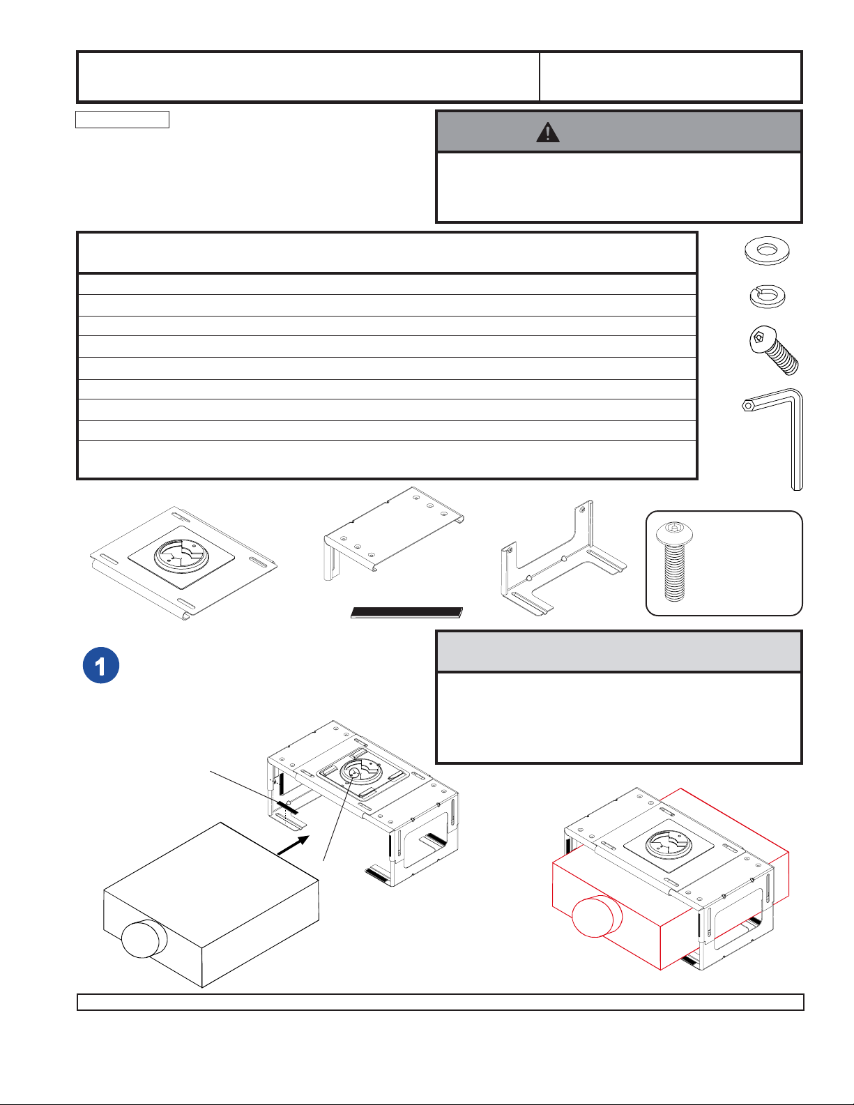
NOTE: *Notch indicates front.
Cut VCR foam (E) to proper length to line
Universal mount assembly (as shown).
Place projector in center of Universal mount
assembly (as shown in far right side).
• Before installation, identify the location of all vents and
ports on the projector to ensure they will not be
obstructed by the universal mount. Blocked vents
may cause damage to the equipment.
CAUTION
E
*
1 of 2
Visit the Peerless Web Site at www.peerlessindustries.com For customer service call 1-800-729-0307 or 708-865-8870.
ISSUED: 07-31-01 SHEET #: 055-9029-5 08-05-04
Page 2
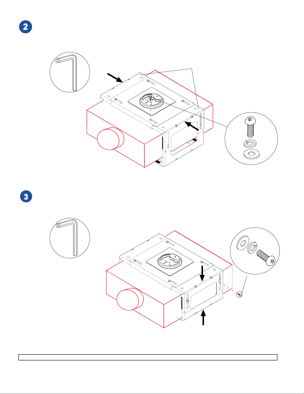
Slide both horizontal slides (B) inward until left and
right sides are against projector (as shown). Fasten
with four M6 screws (D), lock washers (H), and flat
washers (G). Note: Be sure to center top plate (A).
Tighten using 4 mm security allen wrench (F).
F
B
D
H
G
Slide top assembly downward until top and bottom sides
are against projector (as shown). Fasten with four M6
screws (D), lock washers (H), and flat washers (G). Tighten
using 4 mm security allen wrench (F).
F
H
G
D
2 of 2
Visit the Peerless Web Site at www.peerlessindustries.com For customer service call 1-800-729-0307 or 708-865-8870.
© 2004 Peerless Industries, Inc. All rights reserved.
Peerless is a registered trademark of Peerless Industries, Inc.
All other brand and product names are trademarks or registered trademarks of their respective owners.
ISSUED: 07-31-01 SHEET #: 055-9029-5 08-05-04
 Loading...