

Page 1
Installation & Assembly - Solid•Point
™
Wall Mount with T ilt
and Swivel for 60 / 61" Screens
IMPORTANT! Read entire instruction sheet before you start assembly and installation.
Model: PS 2
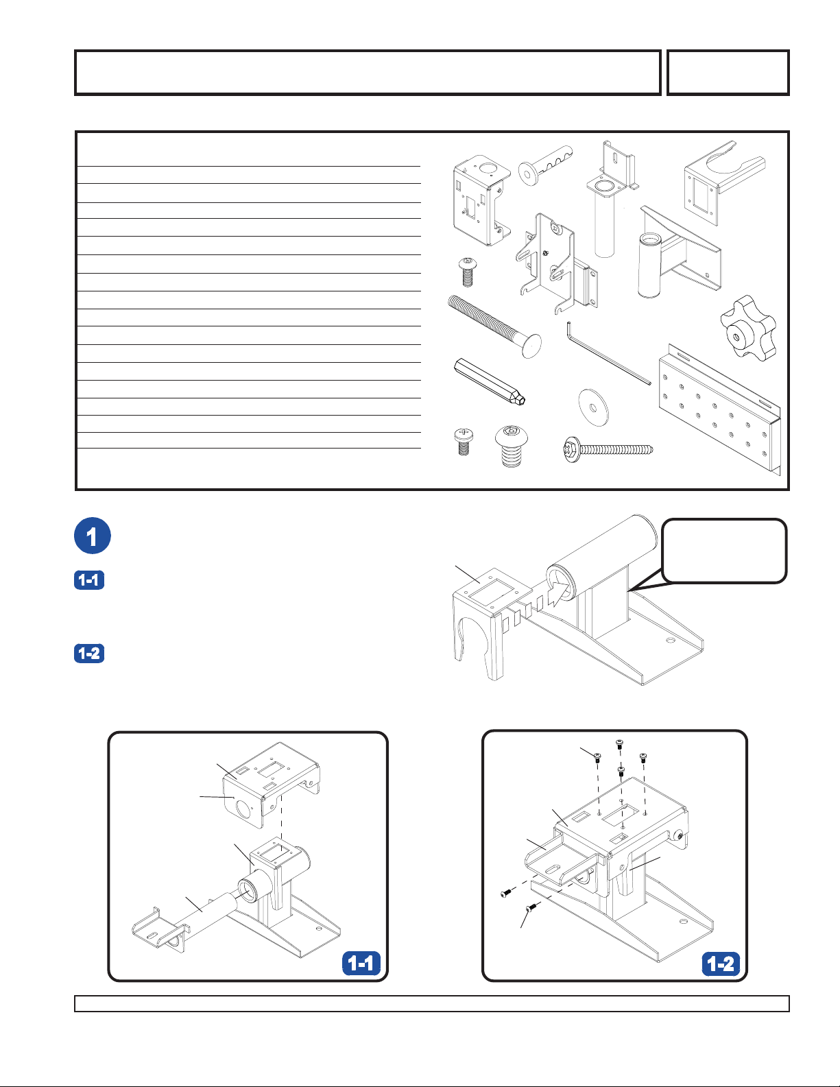
Parts List
PART # QTY. DESCRIPTION
A 200-1434 1 rotation box
B 200-1285 1 tilt pivot retainer assembly
C 520-1055 2 10-32 x 1/2" socket pin screw
D 200-0288 1 pitch roll assembly
E 520-1001 1 carriage bolt 3/8"-16 x 3"
F 520-9263 12 M10 x 1.5 x 15mm penta-pin screw
G 590-1087 1 tilt adjustment knob
H 520-9250 4 M5 x .8 x 10mm phillips screw
I 200-1311 1 swivel lock bracket
J 200-0342 1 wall arm assembly
K 520-9260 1 M10 x 2" penta-pin™ driver
L 200-1343 1 wall plate
M 590-0097 4 concrete anchor
N 540-1008 4 fender washer
O 5SI-015-C03 4 wood screw
P 560-9646 1 4mm security allen wrench
Note: Some parts may appear slightly different than illustrated.
Note: Lay flat on sufrace for ease of assembly.
Place swivel lock bracket (I) on wall arm assembly (J)
as shown to the right.
Place rotation box (A) with threaded holes up over
wall arm assembly (J). Insert tilt pivot retainer
assembly (B) through rotation box (A) and wall arm
assembly (J).
Before you start make sure all parts
listed are included with your product.
I
A
K
C
E
H
F
D
M
N
P
B
I
J
G
L
O
Hole in bottom of
rectangular tube
denotes bottom of
wall arm assembly.
Secure rotation box (A) to swivel lock bracket (I) using
four M5 x .8 x 10mm phillips screws (H). Align holes in
tilt pivot retainer assembly (D) with holes in rotation
box (B) and secure with two 10-32 x 1/2" socket pin
screws (C) as shown.
J
H
A
THREADED
HOLES
I
A
B
I
B
J
1 of 6 ISSUED: 08-28-02 SHEET #: 200-9417-3 12-02-04
Visit the Peerless Web Site at www.peerlessindustries.com For customer service call 1-800-729-0307 or 708-865-8870.
C
J
Page 2
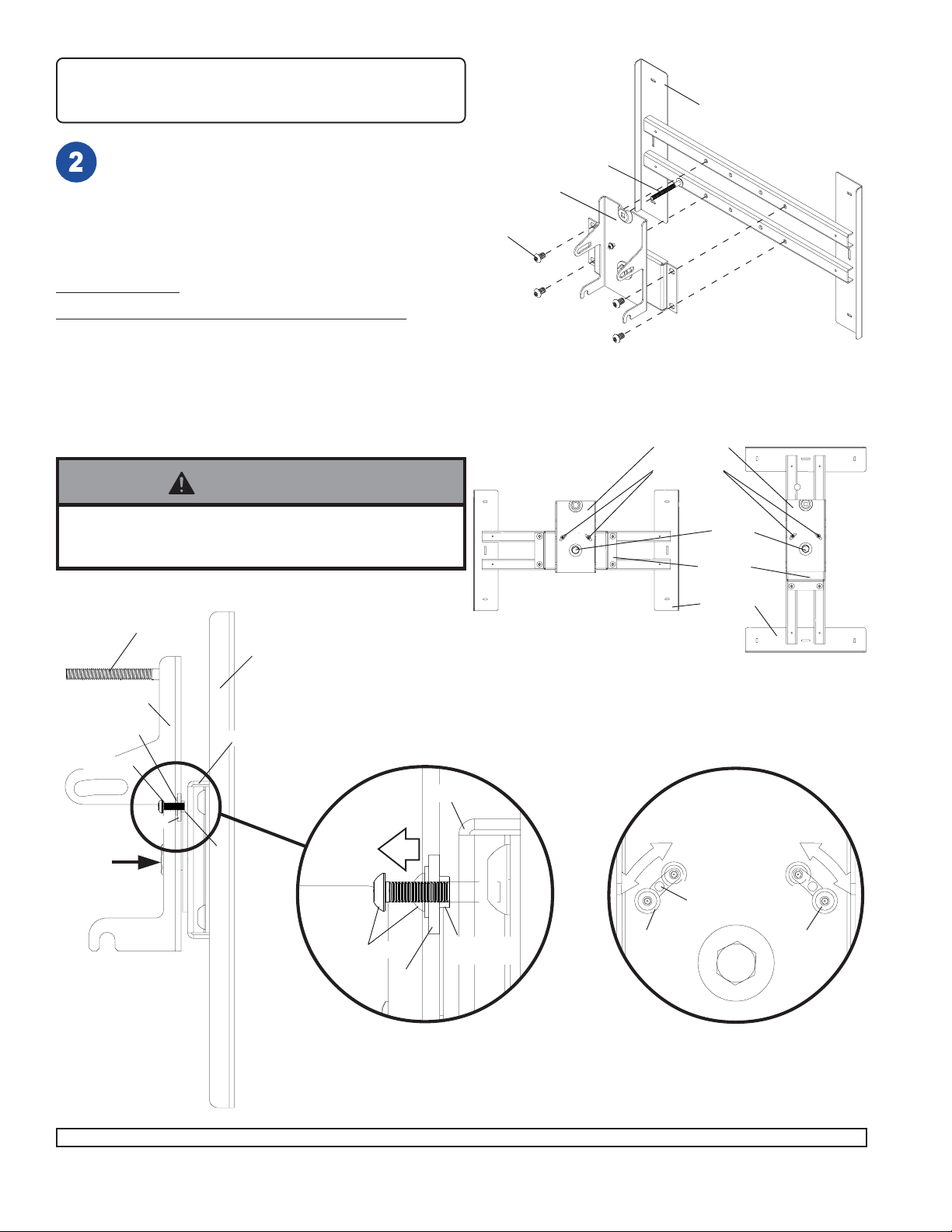
NOTE: Refer to adapter plate instruction sheet (not
included with PS-1) for attachment of adapter plate to
plasma before proceeding with step 2.
Insert and tape carraige bolt (E) into top hole of pitch roll
assembly (D). Attach pitch roll assembly (D) to adapter
bracket with four M10 penta-pin screws (F). Tighten M10
screws with penta-pin driver (K).
Note: Adapter bracket may be ordered separately and
will vary in size and style.
OPTIONAL:
PLASMA IN VERTICAL POSITION
DO NOT REMOVE M5 SCREWS. For vertical orientation, unscrew
two M5 screws until screw is able to move freely in slot of tilt
bracket as shown in details 4 and 4A. Hold adapter bracket
stationary and rotate tilt bracket 90° by hand or using a lever
(example: wood 2 x 4). Align M5 screws with threaded holes on
bracket and tighten two M5 screws back into bracket.
WARNING
GENERIC
ADAPTER
BRACKET
E
D
F
TILT BRACKET
M5 SCREWS
• Do not overtighten screws! Overtightening may hinder
roll option.
CARRIAGE BOLT
GENERIC ADAPTER BRACKET
TILT BRACKET
WASHER
M5 SCREW
SLOT
CENTER
BOLT
BRACKET
RETAINING
SPACER
M5 SCREW
SLOT
BRACKET
RETAINING
SPACER
HORIZONTAL
POSITION
WASHER
CENTER
BOLT
BRACKET
GENERIC
ADAPTER
BRACKET
VERTICAL
POSITION
THREADED
HOLE
M5 SCREW
DETAIL 4
2 of 6 ISSUED: 08-28-02 SHEET #: 200-9417-3 12-02-04
Visit the Peerless Web Site at www.peerlessindustries.com For customer service call 1-800-729-0307 or 708-865-8870.
DET AIL 4A
Page 3

Use stud finder to locate stud centers. Place wall plate
(L) on wall as template, level wall plate and mark center
of studs with pencil. The wall plate can be mounted on
16" centers. When mounted to 16" studs, the wall plate
can be shifted 4" left or right of center if desired.
Note: Hardware provided is for attachment of plasma
mount through standard thickness drywall or plaster
into wood studs. Installers are responsible to provide
hardware for other types of mounting situations.
For Wood Stud Walls drill four 5/32" (4mm) dia. holes 2
1/2" (65mm) deep. Attach wall plate (L) using four #14 x
2.5"(6mm x 65mm) wood screws and washers (O & N).
N
O
L
L
WARNING
• Tighten wood screws so that wall plate is firmly
attached, but do not overtighten. Overtightening can
damage screws, greatly reducing their holding power.
• Never tighten in excess of 80 in • lb (9 N.M.).
• Make sure that mounting screws are anchored into the
center of the studs. The use of an "edge to edge" stud
finder is highly recommended.
L
CONCRETE/CINDER BLOCK INSTALLATION
Place wall plate (L) on wall as template, level
wall plate and mark center of slots with pencil.
WARNING
• When installing Peerless wall mounts on cinder block, verify that you have a minimum of 1 5/8" of actual concrete
surface in the 1/4" diameter hole to be used for the concrete anchors. Do not drill into mortar joints! Be sure to
mount in a solid part of the block, generally 1" minimum from the side of the block. Cinder block must meet ASTM
C-90 specifications. It is suggested that a standard electric drill on slow setting is used to drill the hole instead of
a hammer drill to avoid breaking out the back of the hole when entering a void or cavity .
• Concrete must be 2000 psi density minimum. Lighter density concrete may not hold concrete anchor .
• Make sure that the wall will safely support 4 times the combined load of the equipment and all attached hardware
and components.
3 of 6 ISSUED: 08-28-02 SHEET #: 200-9417-3 12-02-04
Visit the Peerless Web Site at www.peerlessindustries.com For customer service call 1-800-729-0307 or 708-865-8870.
Page 4

For Concrete Walls drill four 1/4" (6mm) dia. holes to a
minimum depth of 2.5" (64mm) on marks made in step
1. Insert anchor (M) in holes flush with wall as shown
(right). Place wall plate (L) over anchor and secure with
four #14 x 2.5" (6mm x 65mm) wood screws and
washers (O & N) as shown at bottom of page. Make sure
wall plate is level before placing fasteners. Tighten all
fasteners.
1
concrete
M
Drill holes and insert anchors (M) in four places
2
O
L
WARNING
• Tighten wood screws so that wall plate is firmly
attached, but do not overtighten. Overtightening can
damage screws, greatly reducing their holding power.
• Never tighten in excess of 80 in • lb (9 N.M.).
N
O
L
N
Place wall plate (L) over anchors (M) and fasten
with screws (O) and washers (N). Do not tighten.
3
Level wall plate and tighten four screws (O).
CUT AW A Y VIEW
M
O
WARNING
• Always attach concrete expansion anchors directly to
load-bearing concrete.
• Never attach concrete expansion anchors to concrete
covered with plaster, drywall, or other finishing material.
Attach wall arm assembly (J) to wall plate (L) using
four M10 penta-pin screws (F).
L
F
4 of 6 ISSUED: 08-28-02 SHEET #: 200-9417-3 12-02-04
Visit the Peerless Web Site at www.peerlessindustries.com For customer service call 1-800-729-0307 or 708-865-8870.
J
Page 5

WARNING
• Use an assistant or mechanical lifting equipment to safely lift and position the plasma T V.
Insert two M10 penta-pin screws (F) into rotation box (A) as shown. Leave approx. 1/4” of exposed thread.
A
.25"
F
Hook pitch roll assembly (D) onto M10 penta-pin screws (F). Insert carriage bolt (E) into slot of tilt pivot retainer assembly
(B) as shown. Install tilt adjustment knob (G).
Install remaining two M10 penta-pin screws (F). HAND TIGHTEN all four M10 penta-pin screws (F) to allow for tilt adjustment. Remove tape from carriage bolt (E). For tilt adjustment, gently push back on the top of plasma to relieve pressure on
knob. Adjust tilt to desired position and tighten tilt adjustment knob (G), then securely tighten all four M10 screws (F) using
penta-pin driver (K).
AS A FINAL PRECAUTION, CHECK ALL F ASTENERS AND TIGHTEN SECUREL Y .
G
F
E
G
B
E
D
F
F
5 of 6 ISSUED: 08-28-02 SHEET #: 200-9417-3 12-02-04
Visit the Peerless Web Site at www.peerlessindustries.com For customer service call 1-800-729-0307 or 708-865-8870.
Page 6

NOTE: Refer to page four of accompanying instruction sheet for attachment of PS 1 with plasma to wall
plate before proceeding with step 4.
Depending on the specific size & weight of the plasma, plasma may appear to lean sideways. Pitch roll assembly (D)
allows plasma to be manually adjusted, so plasma can be horizontal. To adjust, gently rotate plasma by hand to desired
position.
PLASMA
IMPORTANT! Center bolt is factory torqued for optimal performance to adjust for range of plasma sizes.
If it is too difficult to adjust roll of plasma, torque may be adjusted by following the procedures below.
Adjust tilt adjustment knob (G) to allow maximum tilt.
Insert 3/4" open-end wrench (not provided) into side of pitch roll assembly (D) and rotate center bolt counterclockwise
to loosen torque.
IMPORTANT! Do not loosen or tighten more than 1/8 turn.
D
D
G
ADAPTER
A
CENTER
BOLT
PLATE
PLASMA
CENTER
BOLT
WRENCH
6 of 6 ISSUED: 08-28-02 SHEET #: 200-9417-3 12-02-04
Visit the Peerless Web Site at www.peerlessindustries.com For customer service call 1-800-729-0307 or 708-865-8870.
© 2004 Peerless Industries, Inc. All rights reserved.
Peerless is a registered trademark of Peerless Industries, Inc.
All other brand and product names are trademarks or registered trademarks of their respective owners.
 Loading...