

Page 1
Installation and Assembly:
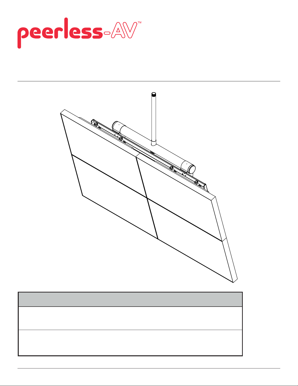
2 x 2 Video Wall Ceiling Mount for 40" - 55"
at Panel Displays
Model: DS-VWT955-2X2
EXTENSION COLUMN
(SOLD SEPARATELY)
COMPATIBILITY
Display width must be a minimum of 36"
Display height must be a minimum of 20.875"
Screen width + horizontal mounting hole pattern must be less than 1745mm
For 200 mm vertical mounting patterns, screen height + mounting hole pattern must be ≤ 890 mm
For 300 mm vertical mounting patterns, screen height + mounting hole pattern must be ≤ 990 mm
For 400 mm vertical mounting patterns, screen height + mounting hole pattern must be ≤ 1090 mm
Maximum Load Capacity: 300 lb (136 kg)
1 of 8
SHEET #: 125-9278-5 09-19-12
Page 2

A
r
Parts List
Description Qty. Part #
tilt bracket 2 145-1710
cross support tube 1 145-1708
B
end cap 2 590-1333
C
fiber washer 1 540-9432
D
retaining collar 1 1800-375
E
M8 x 16 mm phillips screw 4 520-9257
F
M5 x 8 mm phillips screw 3 570-0005
G
adapter bracket 8 145-1711
H
adapter support 2 145-1238
I
4 mm allen wrench 1 560-9646
J
M6 x 6 mm set screw 2 510-9150
K
5/16 split washer 4 540-9405
L
5/16 flat washer 4 540-9406
M
1/4-20 x 3/4 hex head type-F screw
N
1/4-20 nylock nut
O
M8 x 15 mm socket pin screw 16 520-1068
P
M6 x 12 mm socket pin screw 16 520-1050
Q
shoulder washer 16 590-2233
R
safety cable assembly 1 130-8012
S
1/4" washe
T
Parts may appear slightly different than illustrated.
16 520-1321
16 530-9413
16 540-9440
A
B
C D
E
F G H I J
K L M N O P Q
R
S
T
2 of 8
SHEET #: 125-9278-5 09-19-12
Page 3
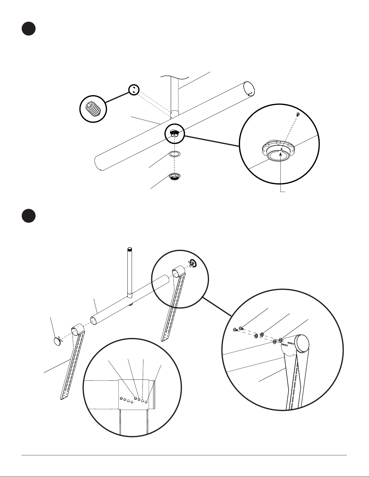
Secure extension column (sold separately) to cross support (B) using retaining collar (E), ber washer (D), and
1
one M5 x 8 mm phillips screw (G). Restrict swivel using two M6 x 6 mm set screws (K).
NOTE: Make sure that M5 x 8 mm phillips screw is positioned inside of notch of extension column as shown in
detail 2.
EXTENSION COLUMN
Detail 1
Detail 2
B
G
K
D
E
Secure tilt brackets (A) to cross support tube (B) using four M8 x 16 mm phillips screws (F), four 5/16’’ split washers
2
(L), and four 5/16’’ at washers (M) in desired tilt position as shown in Detail 3 and 4. Once tilt is established secure
two end caps (C) to cross support tube (B).
EXTENSION
COLUMN NOTCH
A
C
B
5°
10° 15°
Detail 3
20°
3 of 8
A
F
L
M
Detail 4
SHEET #: 125-9278-5 09-19-12
Page 4

Secure two M5 x 8 mm phillips screws (G) to ends of cross support tubes (B) as shown in detail 5.
3
B
G
Detail 5
Attaching Adapter Brackets to Display
NOTE: Make sure to use largest hole pattern on back of display.
4
Attach adapter brackets (H) to back of display using four M6 x 12 mm socket pin screws (Q) or four M8 x 15 mm
socket pin screws (P). The M6 x 12 mm socket pin screws (Q) require nylon shoulder washers (R) as shown
below.
200 mm MIN
600 mm MAX
P or Q
R
USED WITH
M6 (Q)
200 mm
DISPLAY
PLP PLATE
400 mm
300 mm
H
FIGURE 4.1 FIGURE 4.2
4 of 8
SHEET #: 125-9278-5 09-19-12
Page 5

Determine position of horizontal rails (I) using the formula below.
5
1. Locate the position of the lower horizontal rail (I) and attach to tilt brackets (A).
2. Use display height to determine location of upper horizontal rail (I),
NOTE: Lowest horizontal rail (D) position shown below.
NOTE: Horizontal rails (D) must be secured using sixteen 1/4-20 hex head type-F screws (N, step 6).
UPPER HORIZONTAL RAIL
x
DISTANCE
EQUALS
DISPLAY
HEIGHT
LOWER HORIZONTAL RAIL
Attach adapter supports (I) to tilt brackets (A) using sixteen 1/4-20 hex head type-F screws (N) with sixteen
6
1/4’’ washers (T), and sixteen 1/4-20 nylock nuts (O) in a diagonal pattern as shown below.
DISPLAY
HEIGHT
FRONT
5 of 8
O
U
N
Detail 6
Detail 7
SHEET #: 125-9278-5 09-19-12
Page 6

Feed safety cable through extension column (sold separately). Run cable out of the bottom of the
7
extension column (sold separately) and through openings in adapter supports (I) as shown below.
Pull safety cable taught and secure using u-bolt to fasten the looped end to the cable as shown in detail 7.
Wrap excess cable around the extension column (sold separately).
SAFETY CABLE
CLAMP
U-BOLT
SAFETY CABLE
CLAMP NUT
Detail 8
I
6 of 8
SHEET #: 125-9278-5 09-19-12
Page 7

Hook adapter brackets (H) with displays onto adapter supports (I) as shown.
8
Loosely fasten in place using security screw as shown in detail 10.
DISPLAY NOT SHOWN
FOR CLARITY
I
Detail 9
I
H
H
SECURITY SCREW
Detail 10
Adapter Bracket Adjustment
Adapter brackets (H) can be adjusted horizontally as shown. Once adapter brackets (H) are in desired position
9
secure using 4mm allen wrench (K) to lock in place.
7 of 8
SHEET #: 125-9278-5 09-19-12
Page 8

Adapter Bracket Adjustment
Use legend below to determine position of display.
10
NOTE: Each knob can be adjusted independently for ne tuning angle adjustments.
Turn knobs CLOCKWISE to raise display height. Turn knobs CLOCKWISE to push out display.
Turn knobs COUNTER-CLOCKWISE to lower display height. Turn knob COUNTER-CLOCKWISE to pull in display.
UP DOWN IN OUT
KNOB
KNOB
8 of 8
SHEET #: 125-9278-5 09-19-12
 Loading...