

Page 1
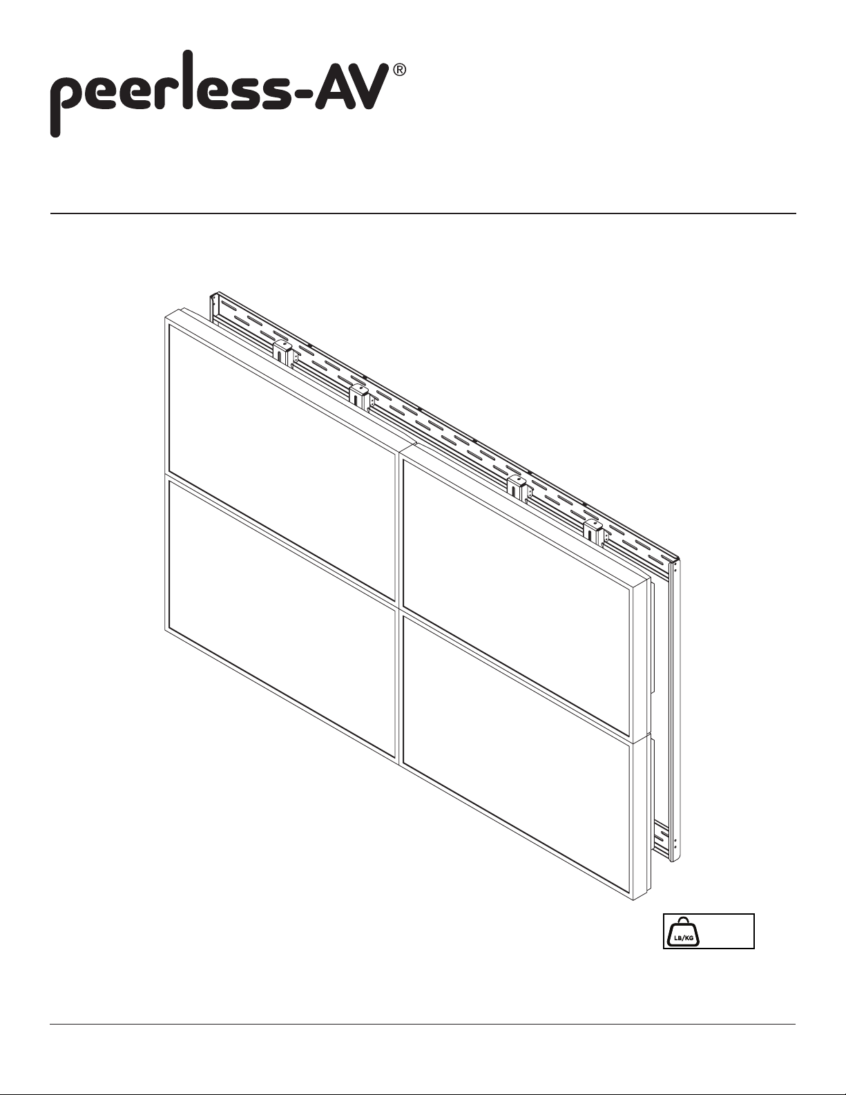
Installation and Assembly:
2 X 2 Wall Matrix
Model: DS-VW646-2X2, DS-VW660-2X2
1 of 10
600 lb
MAX
(272 kg)
ISSUED: 09-22-11 SHEET #: 125-9248-3 04-01-13
Page 2
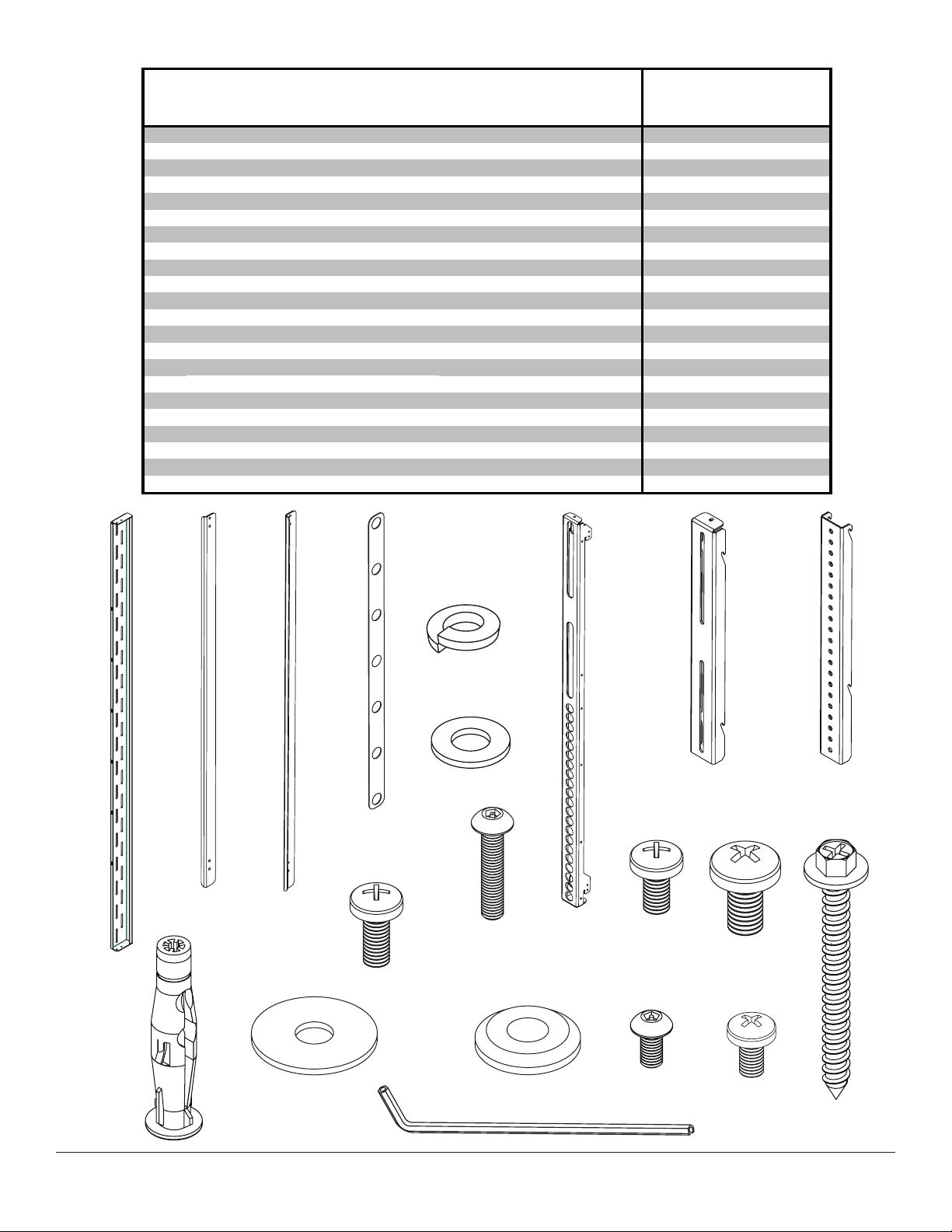
PARTS LIST DS-VW646-2X2 DS-VW660-2X2
A
K
R
V
A
Description Qty. Part # Qty. Part #
wall plate 2 145-1342 2 145-1428
B left connection bracket 1 145-1345 1 145-1431
C right connection bracket 1 145-1344 1 145-1430
D hook on bracket 4 145-1356 4 145-1457
E top adapter bracket 4 145-1347 4 145-1433
F bottom adapter bracket 4 145-1348 4 145-1434
G M6 x 12 mm phillips screw 16 520-1128 16 520-1128
H M8 x 15 mm phillips screw 16 520-9257 16 520-9257
I #14 x 2.5" hex head wood screw 8 5S1-015-C03 10 5S1-015-C03
J concrete anchor 8 590-0320 10 590-0320
fender washer (not used) 16 540-1008 16 540-1008
L nylon shoulder washer 16 590-2233 16 590-2233
M M5 x 10 mm socket pin type-F screw 8 520-1164 8 520-1164
N M5 x 12 mm phillips screw 40 520-1027 40 520-1027
O 4 mm allen wrench 4 560-9646 4 560-9646
P cable tie (not shown) 8 560-9711 8 560-9711
Q mesh sleeve (not shown) 4 600-1014 4 600-1014
#10 lock washer 8 540-1035 8 540-1035
S #10 flat washer 8 540-9400 8 540-9400
T measure plate 1 145-1349 1 145-1349
U M6 x 16 mm phillips screw 16 520-9274 16 520-9274
M5 x 25 mm socket pin screw N/
4 520-1122
A
B
C
T
U
V
R
S
D E
G H
F
I
K
L
M N
J
O
2 of 10
ISSUED: 09-22-11 SHEET #: 125-9248-3 04-01-13
Page 3
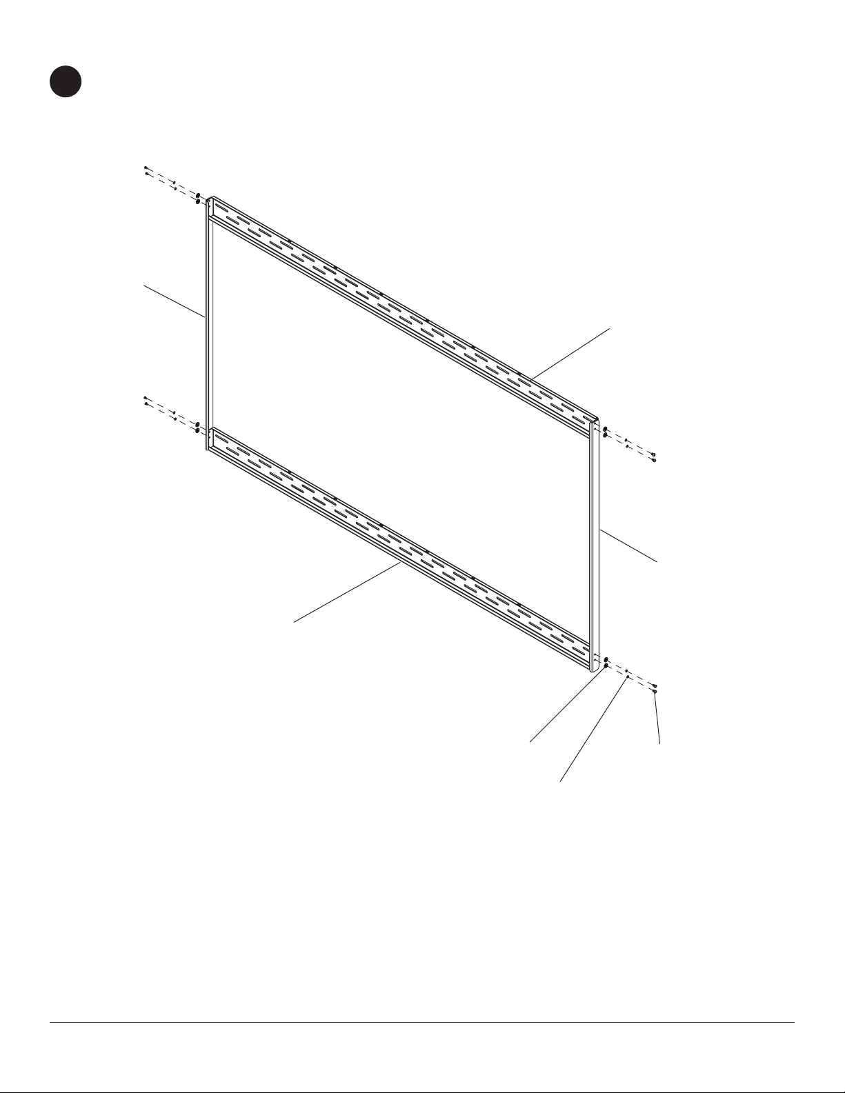
WALL PLATE ASSEMBLY
Attach two wall plates (A) together using left and right connection brackets (B and C) with eight
1
M5 x 12 mm phillips screws (N), #10 at washer (S), #10 lock washer (R) as shown below.
C
A
A
S
B
N
R
3 of 10
ISSUED: 09-22-11 SHEET #: 125-9248-3 04-01-13
Page 4

Installation to Wall Stud
WARNING
• Installer must verify that the supporting surface will safely support the combined load of the equipment and all
attached hardware and components.
• Tighten wood screws so that wall plate is rmly attached, but do not overtighten. Overtightening can damage the
screws, greatly reducing their holding power.
• Never tighten in excess of 80 in. • lb (9 N.M.).
• Make sure that mounting screws are anchored into the center of the stud. The use of an "edge to edge" stud nder
is highly recommended.
• Hardware provided is for attachment of mount through standard thickness drywall or plaster into wood studs. Installers are responsible to provide hardware for other types of mounting situations.
Use a stud nder to locate the edges of the stud. Use of an edge-to-edge stud nder is highly recommended.
2
Based on their edges, draw a vertical line down the stud center. Place wall plate assembly on wall as a template.
Level plate, and mark the center of the eight mounting holes. Make sure that the mounting holes are on the stud
center line. Drill eight 5/32" (4 mm) dia. holes 2-1/2" (65 mm) deep. Make sure that the wall plate assembly is
level, secure it using eight #14 x 2.5" wood screws (I) as shown below.
NOTE: When installing DS-VW660-2x2 two additional #14 x 2.5" wood screws (I) are required.
A
I
4 of 10
ISSUED: 09-22-11 SHEET #: 125-9248-3 04-01-13
Page 5

Installation to Solid Concrete or Cinder Block
WARNING
• When installing Peerless wall mounts on cinder block, verify that you have a minimum of 1-3/8" (35 mm) of actual
concrete thickness in the hole to be used for the concrete anchors. Do not drill into mortar joints! Be sure to mount
in a solid part of the block, generally 1" (25 mm) minimum from the side of the block. Cinder block must meet ASTM
C-90 specications. It is suggested that a standard electric drill on slow setting is used to drill the hole instead of a
hammer drill to avoid breaking out the back of the hole when entering a void or cavity.
• Concrete must be 2000 psi density minimum. Lighter density concrete may not hold concrete anchor.
• Make sure that the wall will safely support four times the combined load of the equipment and all attached hardware
and components.
Make sure that wall plate assembly is level, use it as
2
a template to mark four mounting holes. Drill eight
1/4” (6 mm) dia. holes to a minimum depth of 2.5”
(64 mm). Insert anchors (J) in holes ush with wall
as shown (right). Place wall plate assembly over
anchors and secure with eight #14 x 2.5” screws (I).
Level, then tighten all fasteners.
NOTE: When installing DS-VW660-2x2 two
additional #14 x 2.5” wood screws (I) and anchors
(J) are required.
WARNING
• Tighten screws so that wall plate is rmly attached,
but do not overtighten. Overtightening can damage
screws, greatly reducing their holding power.
• Never tighten in excess of 80 in. • lb (9 N.M.).
• Always attach concrete expansion anchors directly
to load-bearing concrete.
• Never attach concrete expansion anchors to
concrete covered with plaster, drywall, or other
nishing material. If mounting to concrete surfaces
covered with a nishing surface is unavoidable,
the nishing surface must be counter bored as
shown below. Be sure concrete anchors do not
pull away from concrete when tightening screws. If
plaster/drywall is thicker than 5/8" (16 mm), custom
fasteners must be supplied by installer
solid concrete
J
I
1
Drill holes and insert anchors (J).
2
A
I
Place plate (A) over anchors (J) and secure with screws (I).
cinder block
concrete
surface
J
J
plate
CUTAWAY VIEW
wall
plaster/
dry wall
INCORRECT CORRECT
concrete
wall
plate
plaster/
dry wall
concrete
5 of 10
3
Tighten all fasteners.
ISSUED: 09-22-11 SHEET #: 125-9248-3 04-01-13
Page 6

NOTE: Determine Display being used and select orientation below.
3
Fasten eight M5 x 12 mm phillips screws (N) into each hook on bracket (D) leaving 1/8" of exposed thread
as shown below. Repeat step for all hook on brackets (D).
D
OR
N
1/8"
Hook one bottom adapter bracket (F) onto exposed threads on hook on bracket (D) as shown below.
4
Hook one top adapter bracket (E) onto exposed threads on hook on bracket (D) as shown below.
NOTE: Do not tighten screws on hook on bracket (D).
N
1/8"
D
F
D
E
6 of 10
F
E
FINAL
ISSUED: 09-22-11 SHEET #: 125-9248-3 04-01-13
Page 7

ATTACHING ADAPTER BRACKETS TO DISPLAYS
Attach top and bottom adapter brackets (E and F) to back of displays using eight M6 x 12 mm phillips screws (G) with
5
nylon shoulder washer (L), or eight M8 x 15 mm phillips screws (H), or eight M6 x 16 mm phillips screws (U) as shown below.
NOTE: Make sure that nylon shoulder washer (L) is position as shown in detail 1.
G, H or U
D
E
L
Un-hook hook on bracket (D) from top and bottom adapter brackets (E and F) as shown below.
6
E
DISPLAY
DETAIL 1
F
7 of 10
ISSUED: 09-22-11 SHEET #: 125-9248-3 04-01-13
Page 8

Attach two hook on brackets (D) onto wall plate (A) as shown. Determine screen VESA mounting pattern and use
7
measure plate (T) to space hook on bracket as show below.
Repeat step with remaining two hook on brackets (D).
7.87"
(200mm)
11.81"
(300mm)
3.94"
(100mm)
19.69"
(500mm)
23.62"
(600mm)
15.75"
(400mm)
A
T
MEASURE PLATE DETAIL
Hook bottom adapter brackets (F) onto exposed threads on hook on bracket (D) as shown below.
8
Repeat step with second display.
Slide displays together until they are ush with each other.
ALIGN
HOLES
A
D
8 of 10
D
F
ISSUED: 09-22-11 SHEET #: 125-9248-3 04-01-13
Page 9

Hook one top adapter bracket (E) onto exposed threads on hook on bracket (D) as shown below.
9
Repeat step with second display.
E
D
E
Secure top adapter brackets (E) to hook on brackets (D) using four M5 x 10 mm socket pin type-F screws (M) in
10
positions as shown below.
M
E
D
9 of 10
DETAIL 2
ISSUED: 09-22-11 SHEET #: 125-9248-3 04-01-13
Page 10

DS-VW646-2X2
Once displays are in desired position, secure using four security screws located on bottom
11
of hook on brackets (D) as shown in detail 3.
D
SECURITY SCREW
DS-VW660-2X2
Fasten four M5 x 25 mm socket pin screw (V) into bottom of hook on brackets (D)
11
as shown in detail 4.
DETAIL 3
10 of 10
D
V
DETAIL 3
ISSUED: 09-22-11 SHEET #: 125-9248-3 04-01-13
 Loading...