

Page 1
Installation and Assembly:
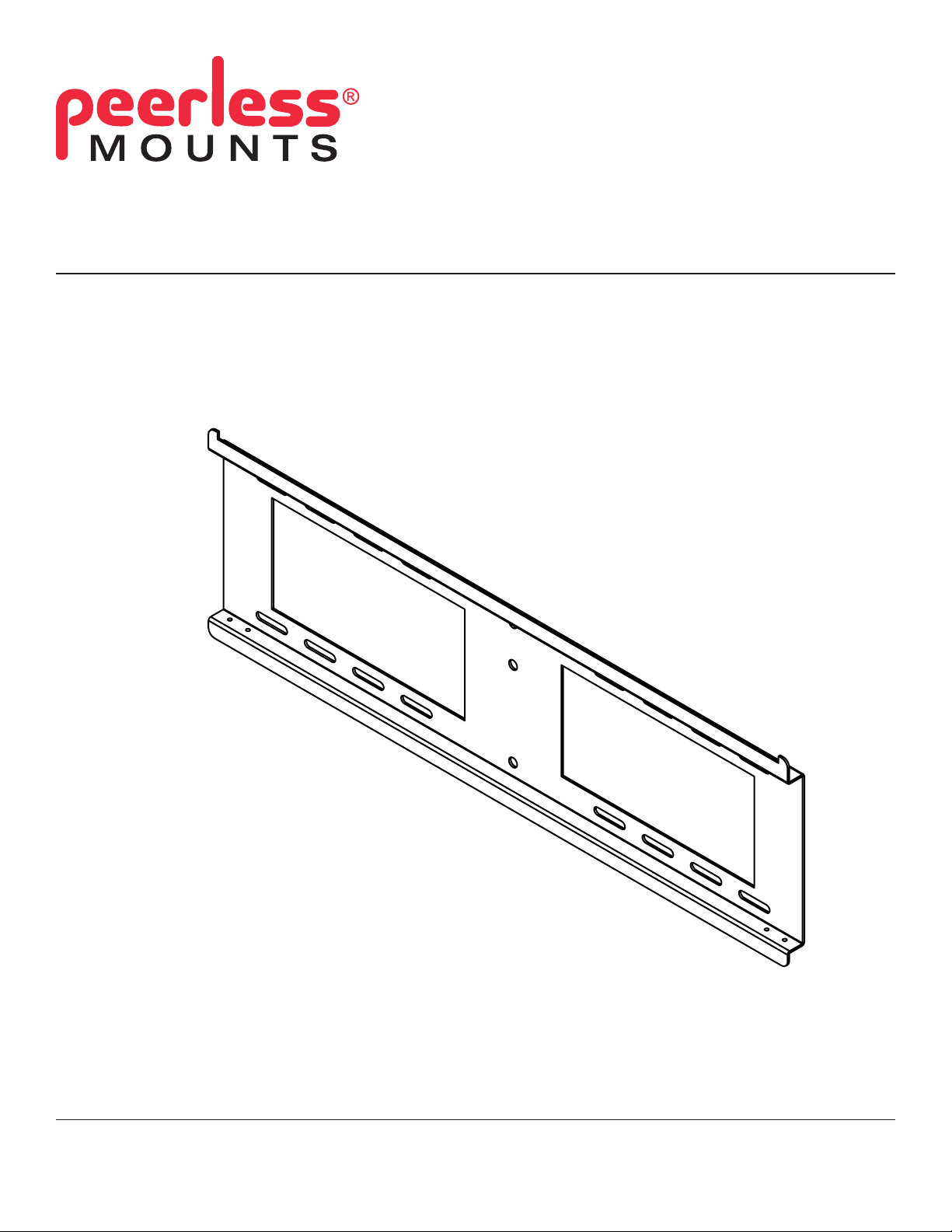
24" Wall Plate Accessory
Model: DS-VL-H024
Maximum Load Capacity: 350 lb (158.8 kg)
3215 W. North Ave. • Melrose Park, IL 60160 • (800) 729-0307 or (708) 865-8870 • Fax: (708) 865-2941 • www.peerlessmounts.com
ISSUED: 06-04-10 SHEET #: 120-9084-1
Page 2
NOTE: Read entire instruction sheet before you start installation and assembly.
WARNING
• Do not begin to install your Peerless product until you have read and understood the instructions and warnings
contained in this Installation Sheet. If you have any questions regarding any of the instructions or warnings, please
call Peerless customer care at 1-800-865-2112.
• This product should only be installed by someone of good mechanical aptitude, has experience with basic building
construction, and fully understands these instructions.
• Make sure that the supporting surface will safely support the combined load of the equipment and all attached hardware and components.
• Never exceed the Maximum Load Capacity. See page 1.
• If mounting to wood wall studs, make sure that mounting screws are anchored into the center of the studs. Use of
an "edge to edge" stud nder is highly recommended.
• Always use an assistant or mechanical lifting equipment to safely lift and position equipment.
• Tighten screws rmly, but do not overtighten. Overtightening can damage the items, greatly reducing their holding
power.
• This product is intended for indoor use only. Use of this product outdoors could lead to product failure and personal
injury.
• This product was designed and intended to be mounted to the following supporting surfaces checked below with
the hardware included in this product as specied in the installation sheet. To mount this product to an alternative
supporting surface, contact Peerless customer care at 1-800-865-2112.
• This product was designed to be installed on the following wall construction only;
WALL CONSTRUCTION ADDITIONAL HARDWARE REQUIRED
x Wood Stud None
x Wood Beam None
x Solid Concrete Contact Customer Service
x Cinder Block Contact Customer Service
Metal Stud Do not attach except with Peerless accessory kit for metal studs;
Contact Customer Service for Peerless accessory kit for metal studs.
Brick Contact Customer Service
Other or unsure? Contact Customer Service
Tools Needed for Assembly
• stud nder ("edge to edge" stud nder is recommended)
• 5/16" socket wrench
• drill
• level
• 5/32" drill bit for wood studs
• 5/16" drill bit for concrete
Accessories:
• DS-ACC-LDCM
cable management accessory (optional)
• ACC-DSV240 adapter brackets (optional)
• ACC-DSV329 adapter brackets (optional)
• ACC-DSV499 adapter brackets (optional)
• ACC-DSV503 adapter brackets (optional)
• ACC-DSV745 adapter brackets (optional)
Table of Contents
Parts List.................................................................................................................................................................................3
Installation to Wood Stud Wall ................................................................................................................................................4
Installation to Solid Concrete/Cinder Block walls ...................................................................................................................5
2 of 6
ISSUED: 06-04-10 SHEET #: 120-9084-1
Page 3

Before you begin, make sure all parts shown are included with your product.
A
PARTS LIST
Description Qty. Part #
wall plate 1 145-1140
B M4 x 12 mm socket pin serrated washer head screw 8 510-1079
C 8 mm concrete anchor 4 590-0320
D wall plate connector 2 024-1045
E 18" 4 mm allen wrench 1 560-1727
F # 14 x 2.5 hex head wood screw 4 5S1-015-C03
Some parts may appear slightly different than illustrated.
B
C
D E
F
A
Installing Additional Wall Plates (optional)
When installing additional wall plates (sold separately) , attach two wall plate connectors (D) on either end of wall
1
plate (A) and fasten with eight M4 x 12 serrated washer head socket pin screws (B) as shown below.
Skip to step 2 on page 5 for
installation to solid concrete or
cinder block walls.
B
D
A
BACK VIEW
3 of 6
ISSUED: 06-04-10 SHEET #: 120-9084-1
Page 4

Installation to Double Wood Stud Wall
WARNING
• Installer must verify that the supporting surface will safely support the combined load of the equipment and all
attached hardware and components.
• Tighten wood screws so that wall plate is rmly attached, but do not overtighten. Overtightening can damage the
screws, greatly reducing their holding power.
• Never tighten in excess of 80 in. • lb (9 N.M.).
• Make sure that mounting screws are anchored into the center of the stud. The use of an "edge to edge" stud nder
is highly recommended.
• Hardware provided is for attachment of mount through standard thickness drywall or plaster into wood studs. Installers are responsible to provide hardware for other types of mounting situations.
Wall plate (A) can be mounted to four studs that are 16" apart. Use a stud nder to locate the edges of the studs.
2
Use of an edge-to-edge stud nder is highly recommended. Based on their edges, draw a vertical line down each
stud’s center. Place wall plate on wall as a template. Level plate, and mark the center of the four mounting holes.
Make sure that the mounting holes are on the stud center lines. Drill four 5/32" (4 mm) dia. holes 2.5" (65 mm)
deep. Make sure that the wall plate is level, secure it using four #14 x 2.5" wood screws (F) as shown in gure 2.2.
A
g. 2.1
STUD
A
4 of 6
F
g. 2.2
ISSUED: 06-04-10 SHEET #: 120-9084-1
Page 5

Installation to Solid Concrete or Cinder Block
WARNING
• When installing Peerless wall mounts on cinder block, verify that you have a minimum of 1-3/8" of actual concrete
thickness in the hole to be used for the concrete anchors. Do not drill into mortar joints! Be sure to mount in a solid
part of the block, generally 1" minimum from the side of the block. Cinder block must meet ASTM C-90 specications. It is suggested that a standard electric drill on slow setting is used to drill the hole instead of a hammer drill to
avoid breaking out the back of the hole when entering a void or cavity.
• Concrete must be 2000 psi density minimum. Lighter density concrete may not hold concrete anchor.
• Make sure that the supporting surface will safely support the combined load of the equipment and all attached hardware and components.
Make sure that wall plate (A) is level, use it as a
2
template to mark four mounting holes. Drill four
5/16" (8 mm) dia. holes to a minimum depth of 2.5"
(64 mm). Insert anchors (C) in holes ush with wall
as shown (right). Place wall plate over anchors and
secure with #14 x 2.5" screws (F). Level, then tighten
all fasteners.
1
Drill holes and insert anchors (C).
concrete
surface
C
WARNING
• Tighten screws so that wall plate is rmly attached,
but do not overtighten. Overtightening can damage
screws, greatly reducing their holding power.
• Never tighten in excess of 80 in. • lb (9 N.M.).
WARNING
• Always attach concrete anchors directly to loadbearing concrete.
• Never attach concrete anchors to concrete covered
with plaster, drywall, or other nishing material.
If mounting to concrete surfaces covered with
a nishing surface is unavoidable, the nishing
surface must be counterbored as shown below.
Be sure concrete anchors do not pull away from
concrete when tightening screws. If plaster/drywall
is thicker than 5/8", custom fasteners must be
supplied by installer.
F
A
C
2
Place plate (A) over anchors (C) and secure with screws (F).
3
Tighten all fasteners.
solid concrete
C
cinder block
plate
CUTAWAY VIEW
wall
plaster/
dry wall
INCORRECT CORRECT
concrete
wall
plate
plaster/
dry wall
concrete
5 of 6
A
F
ISSUED: 06-04-10 SHEET #: 120-9084-1
Page 6

Installing Multiple Wall Plates and Screens (Optional)
Install adapter brackets (sold separately) to screens using adapter bracket instructions.
3
Multiple wall plates and adapter brackets (sold separately) can be used to create multiple screen displays.
WALL PLATE MAY APPEAR
DIFFERENT THAN ILLUSTRATED
ACC-DSV240
(SOLD SEPARATELY)
6 of 6
All other brand and product names are trademarks or registered trademarks of their respective owners.
ISSUED: 06-04-10 SHEET #: 120-9084-1
© 2010, Peerless Industries, Inc. All rights reserved.
 Loading...