

Page 1
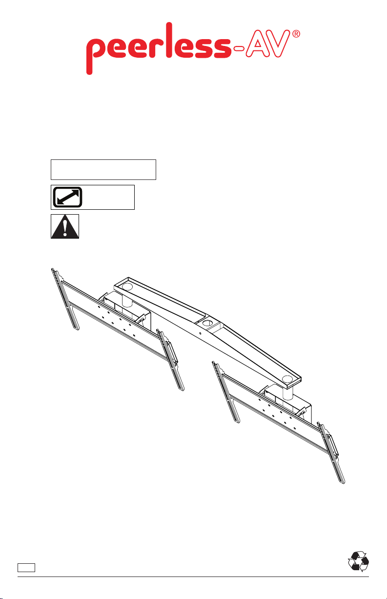
DST970X2
Installation and Assembly
MAX LOAD:
200LBS (90KG)
32" - 65"
(81 - 165 cm)
POSSIBLE INTERFERENCE WITH LARGER
DISPLAYS FACING THE SAME DIRECTION.
ENG
1
2013-05-08 #:125-9426-1
Page 2

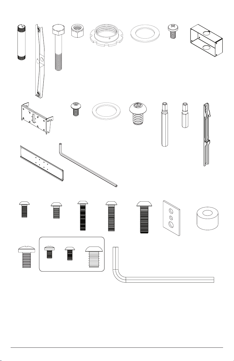
Parts List
Part Description Quantity Part Number
A tube 1.9 od, 6" for ext006 2 128-1094
B dual cross support 44" assy, blk 1 139-1015
C bolt 3/8-16x4.50" hxh, zb 1 520-9548
D nut 3/8-16 nylock 1 530-9310
E retaining collar, black nish 3 1800-375
F wshr ber 1.906idx 2.875 od x 0.062 1 540-9431
G scr tap m5 x .8 x 10mm typ f pan phl zb 1 520-9250
H ceiling arm box, blk 2 201-1062
I plasma/lcs tilt brkt w/logo, blk 2 200-1552
J scr tap m5 x .8 x 10mm f penta pin blk 8 505-9010
K wshr fbr 2.125idx2.875odx.062 2 540-9432
L scr blt m10 x 1.5 x 15mm penta-pin blk 16 520-9263
M M10 x 2" tool driver penta pin 2 520-9260
N M5 x 1" tool driver penta pin 2 520-9249
O smart t 18" slim sec bkt asy, blk 4 201-1511
P large universal plp plate blk 2 201-1110
Q 4mm allen wrench 1 560-9646
R M5 x 12mm skt pin, blk 8 520-1064
S M6 x 12mm skt pin, blk 8 520-1050
T scr bolt M5 x 0.8 x 25mm skt pin 8 520-1122
U M6 x 25mm skt pin, blk 8 520-1211
V scr blt M8 x 25mm skt pin btn, blk 8 520-1101
W 3/4" wide multi washer, blk 8 580-1398
X spacer .344 id x .75 od x .5 ht, blk 8 540-1059
Y scr bolt M8 x 12mm skt pin btn, blk 8 520-1724
Z M5 x .8 x 8mm pan phl type-f, blk 8 520-1167
AA scr bolt m5 x .8 x 10mm skt pin 8 520-1063
BB scr bolt M10 x .5 x 15mm rnd skt blk 8 520-9262
CC 6mm allen wrench 2 560-9716
Z, AA, AND BB HARDWARE OPTIONAL.
DISPLAYS NOT INCLUDED.
2
2013-05-08 #:125-9426-1
Page 3
A B
C
D
E
F
G
H
I
P
J
Q
K
L
M
N
R S T U V W X
Y Z
AA
BB
CC
O
3
2013-05-08 #:125-9426-1
Page 4

1
G
H
Slide dual cross support (B) onto the end of the extension pipe (sold separately). Rotate dual cross support (B)
to desired positon. Drill 3/8" diameter hole through existing hole in dual cross support (B) into extension pipe (sold
separately), repeat on oppostie side. Thread one 4.5” hex bolt (C) through the front of the dual cross support (B) and
extension pipe. Secure .5” hex bolt (C) with one 3/8-16 nylock nut (D). Slide extension pipe ber washer (F) onto the
end of the extension pipe (sold separately) followed by the retaining collar. The Hole must line up with extension pipe
(sold separately) slot. Secure retaining collar (E) with one M5 x 10mm screw (G).
EXTENSION PIPE
NOT INCLUDED
VIEW FROM BELOW DUAL CROSS SUPPORT (B)
B
G
B
D
F
E
C
USE HOLE AS GUIDE TO DRILL 3/8"
HOLE THROUGH EXTENSION PIPE
2 3
Thread two 6” extension columns (A) into both ends
of the dual cross support (B). The holes in the dual
cross support (B) must line up with the slots in the two
6” extension columns (A). Secure both 6” extension
columns (A) using M5 x 10mm penta-pin screws (J).
Leaving ¼” of space, thread eight M10 x 15mm
penta-pin screws (L) into both ceiling arm boxes (H).
H
¼”
B
J
A
x 2 x 2
Slide ceiling arm boxes (H) onto the 6” extension columns (A) followed by two extension column ber washers (K)
and two retaining collars (E). The holes in retaining collars (E) must line up with the slots in the two 6” extension
columns (A). Secure both ceiling arm boxes (H) using M5 x 10mm penta-pin screws (J).
A
H
REAR VIEW OF
CEILING ARM
BOXES (H)
L
K
E
J
J
x 2
4
2013-05-08 #:125-9426-1
Page 5

5
Secure PLP plates (P) to tilt brackets (I) using M10 x 15mm penta-pin screws (L). Hook PLP plates (P) to ceiling
arm boxes (H). Tighten the M10 x 15mm penta-pin screws (L) to secure assembly.
EXTENSION PIPE
NOT INCLUDED
P
L
I
6
Center adapter brackets (O) vertically
on back of display.
O
O
OPTIONAL
Use of spacers.
P
H
x 2
X
X
O
X
R
5
X
W
T
W
2013-05-08 #:125-9426-1
X
W
U
W
S
V
Y
Page 6

9
Hook displays onto PLP plates (P).
Adjust displays horizontally as needed.
P
Secure displays by tightening adapter bracket screw.
ADAPTER BRACKET SCREW
6
2013-05-08 #:125-9426-1
Page 7

10
Adjust displays as desired.
7
2013-05-08 #:125-9426-1
Page 8

Peerless-AV
2300 White Oak Circle
Aurora, IL 60502
Email: tech@peerlessmounts.com
Ph: (800) 865-2112
Fax: (800) 359-6500
www.peerless-av.com
© 2013, Peerless Industries, Inc.
8
2013-05-08 #:125-9426-1
 Loading...