

Page 1
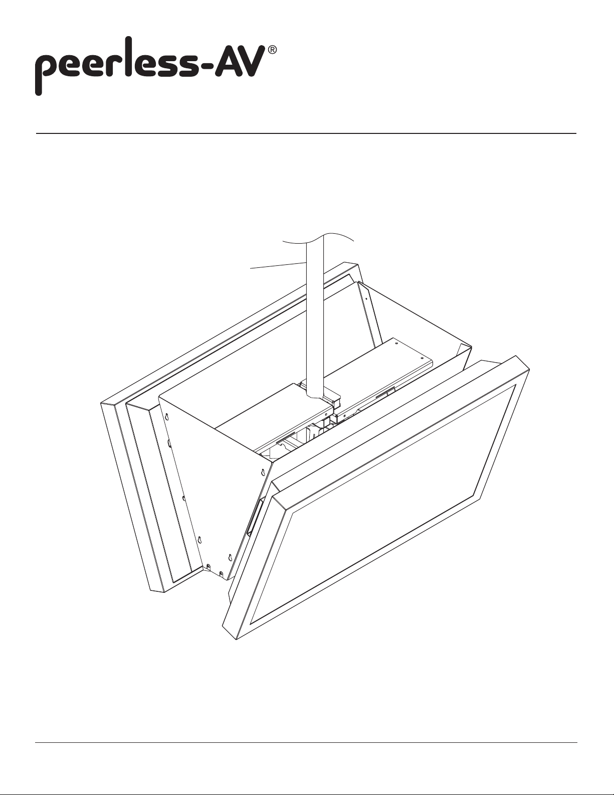
Installation and Assembly: Back to Back Ceiling Mount
Model: DST965
* SEE NOTE
* NOTE: DST965 WILL NOT WORK WITH ADJUSTABLE
EXTENSION COLUMNS AEC006009, OR AEC012018
2300 White Oak Circle • Aurora, IL 60502 • (800) 865-2112 • Fax: (800) 359-6500 • www.peerlessmounts.com
Maximum Load Capacity: 300 Ib (136 kg)
ISSUED: 10-24-11 SHEET #: 125-9260-2 2-1-13
Page 2
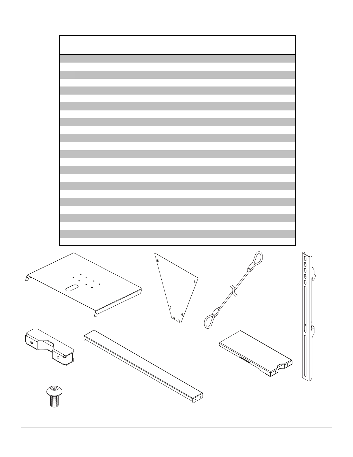
Before you start make sure all parts listed are included with your product.
A
V
X
PARTS LIST
Description Qty. Part #
main cover 2 145-1452
B side cover 2 145-1453
C cable assembly 1 600-0033
D adapter bracket 4 201-1511
E component shelf clamp 2 145-1180
F bottom bracket 1 145-1454
G component shelf 2 145-1179
H M5 x 10 mm socket pin type-F screw 12 520-1164
I 1/4-20 X 2" socket screw 4 520-1010
J cable wire clamp 1 560-0104
K cable bracket 2 145-1178
L safety belt (not shown) 1 170-8039-1
M adapter plate 2 201-1110
N 4 mm security driver tool 1 560-1133
O interface bracket 1 200-1090
P tilt bracket 2 200-1552
Q M10 x 1.5 x 15 mm penta-pin™ screw 16 520-9263
R M5 x .8 x 10 mm self-tapping penta-pin screw 1 505-9010
S #8 x 3/8" truss head sheet metal screw 1 520-1078
T M10 x 2" penta-pin tool 1 520-9260
U M5 x 1" penta-pin tool 1 520-9249
2.125" ID x 2.875" OD x .062" H fiber washer 1 540-9432
W retaining collar 1 1800-375
18" allen wrench 1 560-1727
A B C
E
F
H
D
G
2 of 11
ISSUED: 10-24-11 SHEET #: 125-9260-2 2-1-13
Page 3
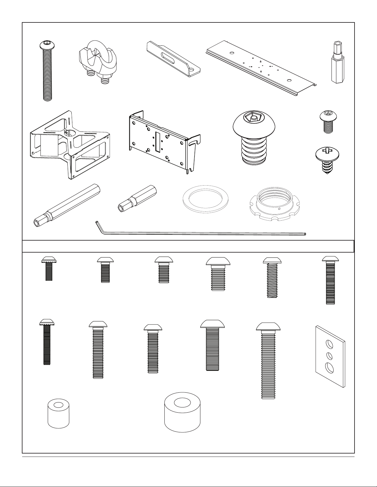
Some parts may appear slightly different than illustrated.
I
J
K
O P Q
T U
V
W
M
N
R
S
M4 x 12 mm (12)
510-1079
M4 x 25 mm (8)
510-1082
X
M5 x 12 mm (8)
520-1064
M6 x 30 mm (8)
520-1067
Security Adapter Bracket Fasteners
M6 x 12 mm (8)
520-1050
M6 x 25 mm (8)
520-1211
M8 x 15 mm (12)
520-1068
M8 x 25 mm (8)
520-1101
M6 x 20 mm (8)
520-9554
M8 x 40 mm (8)
520-1152
M5 x 25 mm (8)
520-1122
multi-washer (8)
580-1036
I.D. .22" (5.6 mm) (8)
540-1057
I.D. .34" (8.7 mm ) (8)
540-1059
3 of 11
ISSUED: 10-24-11 SHEET #: 125-9260-2 2-1-13
Page 4
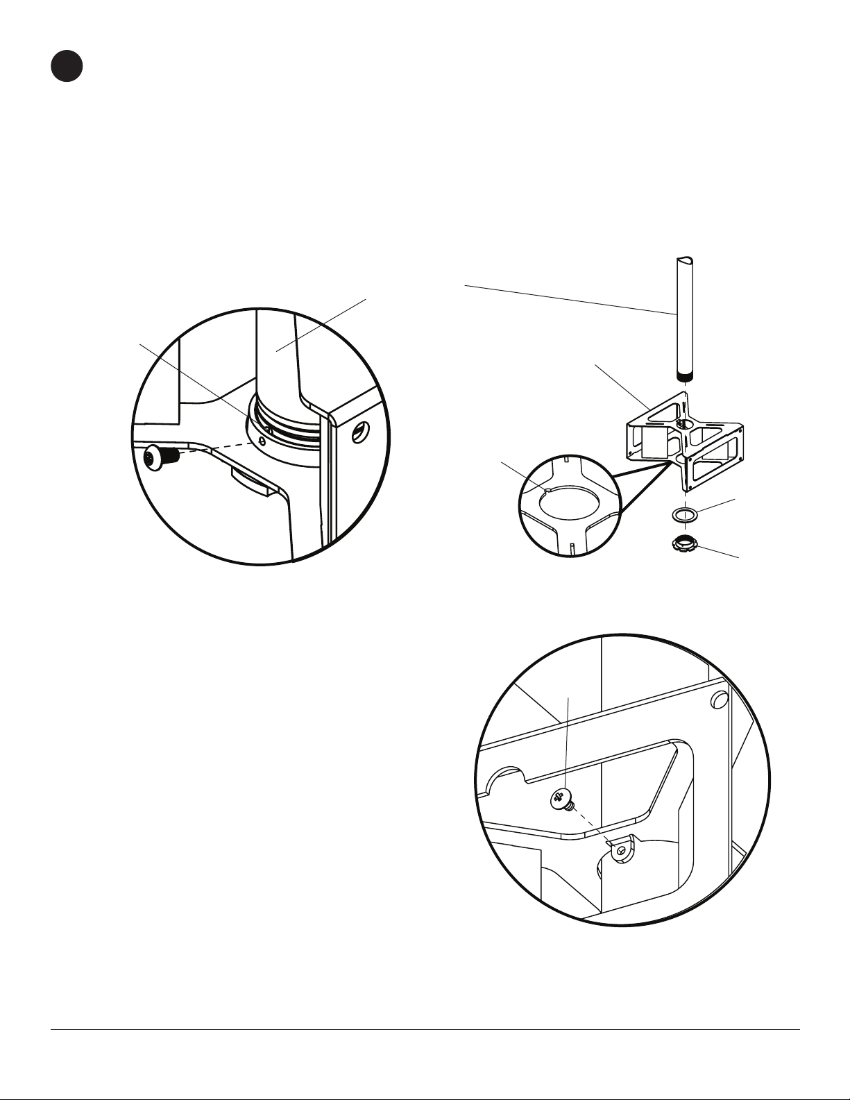
Note: Notch indicates bottom of interface bracket (O) as shown in detail 1.
1
Slide interface bracket (O) onto adjustable extension column (not supplied) and attach using ber washer (V) and
retaining collar (W) as shown in gure 1.1.
Carefully thread retaining collar (W) onto end of extension column. Tighten retaining collar (W) at least four
complete turns ending with one of the small holes aligned with slot in the end of extension column. Insert and
tighten M5 x 10 mm penta-pin screw (R) using M5 x 1" penta-pin tool (U) as shown in gure 1.2.
Secure Interface bracket (O) into place using one #8 x 3/8" truss head sheet metal screw (S)
as shown in detail 2.
ADJUSTABLE
EXTENSION
COLUMNS
SLOT
O
NOTCH
R
Detail 1
Figure 1.2 Figure 1.1
S
V
W
4 of 11
Detail 2
ISSUED: 10-24-11 SHEET #: 125-9260-2 2-1-13
Page 5

Screw eight M10 x 15 mm penta-pin screws (Q) into interface bracket (O) leaving approximately
2
1/4" of exposed thread as shown below and in detail 3.
Q
O
Q
Attaching Component Shelf
Secure two component shelves (G) to adjustable extension column (not supplied) using two component shelf
3
clamps (E) and four 1/4-20 X 2" socket screws (I).
NOTE: Make sure that component shelves are in the orientation as shown in detail 4.
Detail 3
1/4"
O
ADJUSTABLE
EXTENSION
COLUMNS
I
G
E
G
5 of 11
G
E
G
Detail 4
ISSUED: 10-24-11 SHEET #: 125-9260-2 2-1-13
Page 6

Secure four M10 x 15 mm penta-pin screws (Q) through
4
cable bracket (K), tilt plate (P), main cover (A), and adapter
plate (M), and as shown below.
Repeat with second support assembly.
Q
K
P
A
TOP
M
Hook tilt plate (P) and support assembly onto M10 x 15 mm penta-pin screws (Q).
5
Repeat with second support assembly.
P
SUPPORT ASSEMBLIES
Q
6 of 11
ISSUED: 10-24-11 SHEET #: 125-9260-2 2-1-13
Page 7

Run cable assembly (J) down through extension column around and through two cable brackets (K)
6
as shown below.
Secure cable to itself using u-bolt, clamp and nuts from cable wire clamp (J).
CABLE
NUT
U-BOLT
CLAMP
K
C
K
Secure bottom bracket (F) to support assemblies using M5 x 10 mm socket pin Type F screws (H)
7
as shown below.
SUPPORT ASSEMBLIES
F
SUPPORT ASSEMBLIES
H
7 of 11
ISSUED: 10-24-11 SHEET #: 125-9260-2 2-1-13
Page 8

Installing Adapter Brackets
WARNING
• Tighten screws so adapter brackets are rmly attached. Do not tighten with excessive force. Overtightening can
cause stress damage to screws, greatly reducing their holding power and possibly causing screw heads to become
detached. Tighten to 40 in. • lb (4.5 N.M.) maximum torque.
• If screws don't get three complete turns in the screen inserts or if screws bottom out and bracket is still not tightly
secured, damage may occur to screen or product may fail.
To prevent scratching the screen, set a cloth on a at, level surface that will support the weight of the screen. Place
8
screen face side down. If screen has knobs on the back, remove them to allow the adapter brackets to be attached.
Place adapter brackets (D) on back of screen, align to holes, and center on back of screen as shown below. Attach
the adapter brackets to the back of the screen using the appropriate combination of screws, multi-washers and
spacers as shown in step 8-1 and step 8-2.
NOTE: Top and bottom holes on screen must always be used.
Verify that all holes are properly aligned, and then tighten screws using a phillips screwdriver.
NOTE: Tighten using security allen wrench (X).
X
D
Notes:
• The number of fasteners used will vary,
depending upon the type of screen.
• Multi-washers and spacers may not be
used, depending upon the type of screen.
• Use the corresponding hole in the multi-
washer that matches your screw size as
shown.
CENTER BRACKETS
VERTICALLY ON BACK OF
SCREEN
X
Note: "X" dimensions should be equal.
MULTI-WASHER
MEDIUM HOLE FOR M5 SCREWS
SMALL HOLE FOR M4 SCREWS
LARGE HOLE FOR M6 SCREWS
NOTE: For at back screens proceed to step 8-1. For bump-out or recessed back screen skip to step 8-2.
8 of 11
ISSUED: 10-24-11 SHEET #: 125-9260-2 2-1-13
Page 9

For Flat Back Screen
8-1
Begin with the shortest length screw, hand thread through multi-washer and adapter bracket into screen as
shown below. Screw must make at least three full turns into the mounting hole and t snug into place. Do not
over tighten. If screw cannot make three full turns into the screen, select a longer length screw from the bafed
fastener pack. Repeat for remaining mounting holes, level brackets and tighten screws.
NOTE: Spacers may not be used, depending upon the type of screen.
If you have any questions, please call Peerless customer care at 1-800-865-2112.
g. 8.1
DISPLAY
MULTI-WASHER
SCREW
ADAPTER
BRACKET
(BB)
For Bump-out or Recessed Back Screen
8-2
Begin with longer length screw, hand thread through multi-washer, adapter bracket and spacer in that order into
screen as shown below. Screw must make at least three full turns into the mounting hole and t snug into place.
Do not over tighten. If screw cannot make three full turns into the screen, select a longer length screw from the
bafed fastener pack. Repeat for remaining mounting holes, level brackets and tighten screws.
DISPLAY
SPACER
If you have any questions, please call Peerless customer care at 1-800-865-2112.
g. 8.2
MULTI-WASHER
SCREW
ADAPTER
BRACKET
(BB)
9 of 11
ISSUED: 10-24-11 SHEET #: 125-9260-2 2-1-13
Page 10

Mounting and Removing Flat Panel Screen
WARNING
• Always use an assistant or mechanical lifting equipment to safely lift and position the plasma television.
Hook adapter brackets (D) onto adapter plate (M), then slowly swing screen in as shown. Turn safety/security
9
screws clockwise at least six times to prevent screen from being removed as shown in detail 5.
Tighten using wrench (X).
Screen can be adjusted horizontally if desired as shown in gure 9.1.
NOTE: To lock the screen down, tighten safety/security screws to adapter bracket as shown in detail 5.
To remove screen from mount, loosen safety/security screws, swing screen away from mount, and lift screen off of
mount.
D
Fig. 9.1
M
DETAIL 5
M
SAFETY/SECURITY
SCREWS
10 of 11
D
ISSUED: 10-24-11 SHEET #: 125-9260-2 2-1-13
Page 11

Secure PC component to component shelf (G)
10
with safety belt (L) through slots on component
shelf (G) using instructions provided with
safety belt.
PC COMPONENT
G
SLOTS
Thread four M5 x 10 mm socket pin Type F screws
11
(H) into support assemblies leaving 1/8" of exposed
thread. Repeat with second side.
L
H
H
1/8"
Hook side cover (B) keyholes onto exposed screws.Tighten all M5 x 10 mm socket pin Type F screws (H).
12
Repeat with second side cover.
B
KEYHOLES
EXPOSED SCREWS (H)
11 of 11
All other brand and product names are trademarks or registered trademarks of their respective owners.
ISSUED: 10-24-11 SHEET #: 125-9260-2 2-1-13
© 2010, Peerless Industries, Inc. All rights reserved.
 Loading...