

Page 1
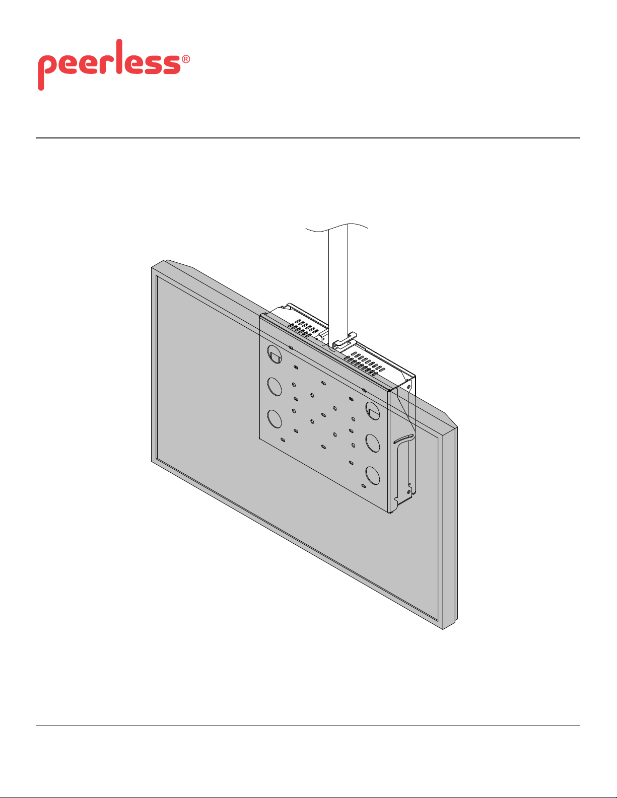
Installation and Assembly:
Mount - Wall/Ceiling Mount
Model: DST360
Max Load Capacity: 150 lb (68. kg)
3215 W. North Ave. • Melrose Park, IL 60160 • (800) 729-0307 or (708) 865-8870 • Fax: (708) 865-2941 • www.peerlessmounts.com
ISSUED: 06-15-09 SHEET #: 145-9008-4 01-24-12
Page 2
NOTE: Read instruction sheet before you st art installation and assembly .
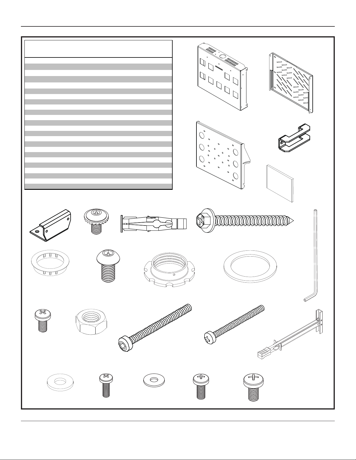
PARTS LIST
Descrip tion Qty. Pa r t #
A main support box 1 145-1050
B access plate 1 145-1049
C adapter pl ate 1 145-1172
D
pinc h bracket
E
yaw lock bracket
F M6 x 1 2 m m socket pi n s errated wash er head screw 6 510-1050
G concrete anchor 6 590-0320
H #14 x 2. 5 he x phillips wood s crew 6 5S1-015-C03
I 4 mm al l en wrench 1 560-9646
J rubber pad 4 590-1159
K 2" snap bus hing 1 590-1149
L M8 x 1 5 m m socket pi n s crew 4 520-1068
M retain in g collar 1 1800-375
N washer 1 540-9432
O M5 x 10 mm t ype F s crew 1 520-9250
P M5 nylock nut 2 530-1019
Q M5 x 55 mm s ocket sc re w 2 520-1193
R 1/4 - 20 x 2.5 phill i ps screw 6 520-9521
S toggler 6 560-9708
T 1/4 - 20 was he r 6 540-9440
U M4 x 1 2 m m phi l l i ps screw 4 504-9013
V #8 was he r 4 540-1001
W M5 x 1 2 m m phi l l i ps screw 4 520-1027
X M6 x 12 mm phi l l i ps sc rew 4 520-11 28
NOTE: Some parts may appear slightly different than illustrated
1 130-1073
1 140-1019
EF G
C
A
H
B
D
J
I
KLM N
OP Q R S
TUVWX
2 of 11
ISSUED: 06-15-09 SHEET #: 145-9008-4 01-24-12
Page 3
For Installation to Column skip to Step 10 on Page 9
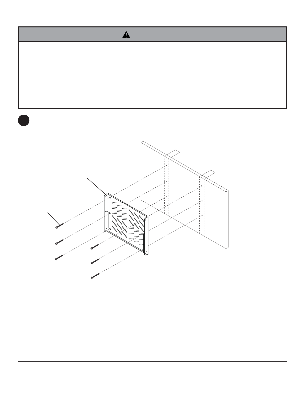
Installation to Wood Stud Wall
WARNING
• Installer must verify that the supporting surface will safely support the combined load of the equipment and all attached
hardware and components.
• Tighten wood screws so that wall plate is firmly attached, but do not overtighten. Overtightening can damage the
screws, greatly reducing their holding power.
• Never tighten in excess of 80 in. • lb (9 N.M.).
• Make sure that mounting screws are anchored into the center of the stud. The use of an "edge to edge" stud finder is
highly recommended.
• Hardware provided is for attachment of mount through standard thickness drywall or plaster into wood studs. Installers
are responsible to provide hardware for other types of mounting situations.
Using access plate (B) as a template, drill six 5/32" (4 mm) dia. holes to a minimum depth of 2.5" (64 mm). Attach
1
access plate (B) to centers of wood studs using six #14 x 2.5" wood screws (H) shown.
H
B
3 of 11
ISSUED: 06-15-09 SHEET #: 145-9008-4 01-24-12
Page 4
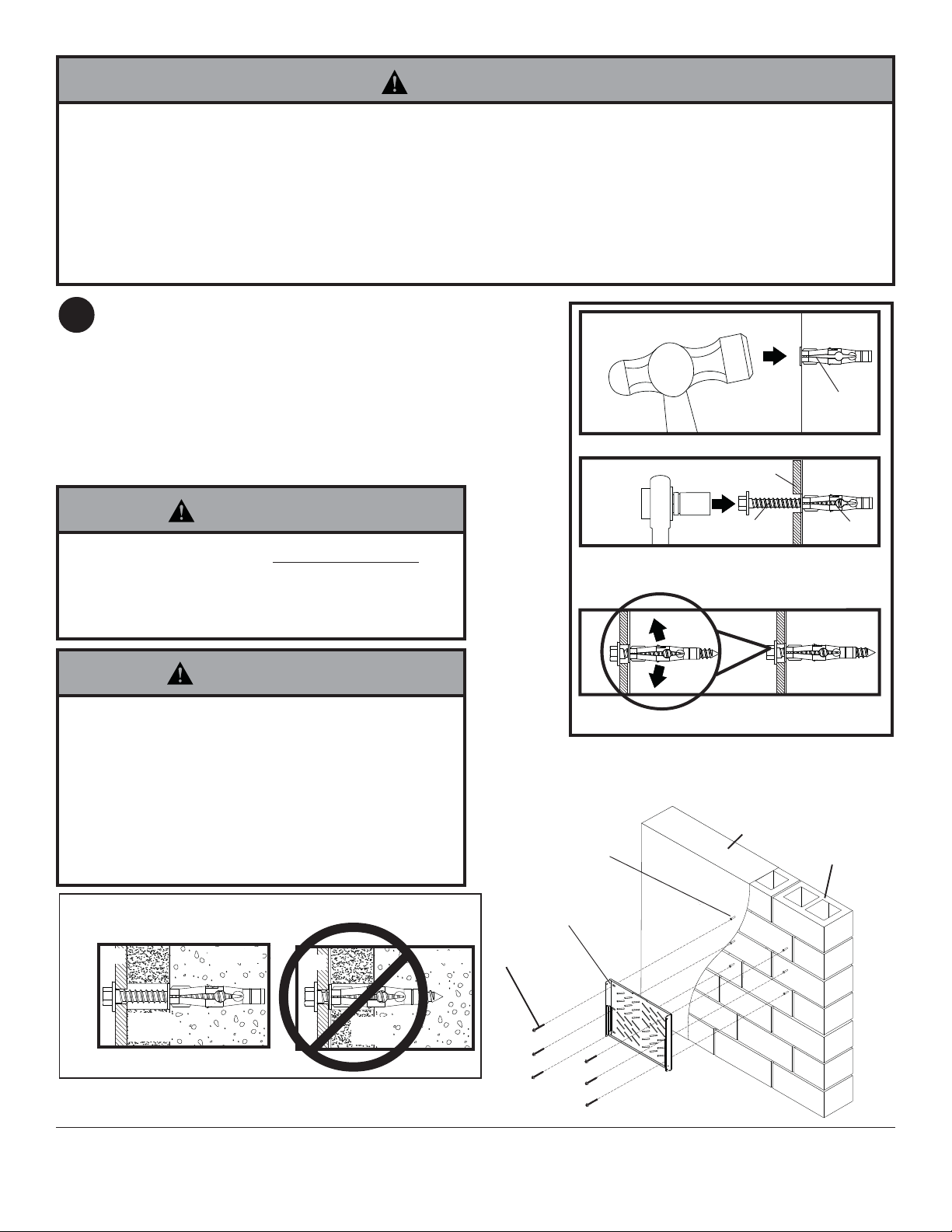
Installation to Solid Concrete and Cinder Block Wall
WARNING
• When installing Peerless wall mounts on cinder block, verify that you have a minimum of 1-3/8" of actual concrete
thickness in the hole to be used for the concrete anchors. Do not drill into mortar joints! Be sure to mount in a solid
part of the block, generally 1" minimum from the side of the block. Cinder block must meet ASTM C-90 specifications.
It is suggested that a standard electric drill on slow setting is used to drill the hole instead of a hammer drill to avoid
breaking out the back of the hole when entering a void or cavity .
• Concrete must be 2000 psi density minimum. Lighter density concrete may not hold concrete anchor.
• Make sure that the supporting surface will safely support the combined load of the equipment and all attached hardware and components.
Position access plate (B) at desired position on wall. Use
2
access plate (B), making sure that it is level, as a template to mark holes. Drill six 5/16" (8 mm) dia. holes to a
minimum depth of 2-1/2" (64 mm). Concrete must be 2000
psi density minimum. Insert anchors (G) in holes flush
with wall as shown in figure 2.3. Place access plate (B)
over anchors and secure with six #14 x 2-1/2" (6 mm x 65
mm) wood screws (H) as shown in figure 2.4. Make sure
wall plate is level and tighten all fasteners.
1
Drill holes and insert anchors.
2
B
concrete
wall
G
WARNING
• Tighten wood screws firmly , but do not overtighten.
Overtightening can damage the screws, greatly
reducing their holding power.
• Never tighten in excess of 80 in • lb (9 N.M.).
WARNING
• Concrete anchors are not intended for attachment to
concrete wall covered with a layer of plaster, drywall,
or other finishing material as shown below. If mounting
to concrete wall covered with plaster/drywall is
unavoidable, plaster/drywall (up to 5/8" thick) must be
counterbored as shown below. Be sure concrete
anchors do not pull away from concrete when tightening screws. If plaster/drywall is thicker than
5/8", custom fasteners must be supplied by installer.
B
CORRECT
concrete
B
INCORRECT
concrete
H
H
Place access plate (B) over anchors and secure with
screws (H).
3
Tighten all fasteners.
SOLID CONCRETE
fig 2.3
CINDER BLOCK
G
B
G
CUT AW A Y VIEW
plaster/
dry wall
plaster/
dry wall
4 of 11
fig 2.4
ISSUED: 06-15-09 SHEET #: 145-9008-4 01-24-12
Page 5

FOR MET AL STUD W ALLS ONLY: Drill six 1/2"
3
(13 mm) dia. holes through drywall and studs at
locations corresponding to wall plate. Insert togglers
(S) as shown below.
WARNING
• Product must be mounted through drywall that has a
minimum thickness of 1/2" and into metal studs, 26
gauge or heavier.
• Make sure that togglers are anchored into the center
of the studs as shown in figure 3.1. The use of an
"edge to edge" stud finder is highly recommended.
Pivot end of toggler (S).
3-1
S
S
∅ 1/2"
(13 mm)
3-2
3-3
3-4
3-5
Push into hole.
Rotate toggler (S)
clockwise to wedge it
against inside walls
of metal stud.
Slide plastic cap
forward while pulling
back firmly on ring.
Break off excess.
fig. 3.1
5 of 11
ISSUED: 06-15-09 SHEET #: 145-9008-4 01-24-12
Page 6

Align wall plate with
3-6
hole in wall and
fasten using
1/4-20 x 2.5" screw
(R) and 1/4"
washer (T).
R
T
R
T
B
access plate
S
Select mounting hole pattern and secure adapter plate (C) to screen using screws (U,W, or X) and washers
4
(V) if required.
PLP Adapter Plate
200 mm x 200 mm
300 mm x 300 mm200 mm x 100 mm
PLP ADAPTER PLATE
Mounting Holes
NOTE: First attach
the vertical uprights
to the screen
detailed in the PLP
Adapter Plate
instructions
Using Screws (U,W, or X) and washers (V) as required
6 of 11
vertical uprights
ISSUED: 06-15-09 SHEET #: 145-9008-4 01-24-12
Fasteners provided by
dedicated adapter plate
Page 7

Secure media component to main support box (A) using strap provided with main support box (A), and rubber pads
5
(J) for support and ventilation.
MEDIA COMPONENT
Secure 2" snap bushing (K) as desierd.
A
Secure main support box (A) to
6
access plate (B) with four M8 x 15 mm
socket pin screws (L). Tighten using allen
wrench (I).
B
J
K
Thread two M6 x 12 mm socket pin screws (F) into
7
main support box (A) leaving 1/8" exposed thread as
shown in detail 1. Hook screen and adapter plate onto
exposed screws.
STRAP
MEDIA COMPONENT
A
F
A
L
7 of 11
A
1/8"
Detail 1
ISSUED: 06-15-09 SHEET #: 145-9008-4 01-24-12
Page 8

Secure two M6 x 12 mm socket pin screws (F)
8
into main support box (A) at desired tilt. Tighten
using allen wrench (I).
F
A
Accessing Media Component
Loosen top two M8 x 15 mm socket pin screws (L) 1/4 turn and temporaliy remove bottom two M8 x 15 mm socket
9
pin screws (L) on main support box (A) as shown. Swing screen forward and swing support brackets downward to
brace screen in open position.
L
LOOSEN SCREWS 1/4
TURN ON BOTH SIDES
L
REMOVE
A
A
8 of 11
SUPPORT BRACKETS
(BOTH SIDES)
ISSUED: 06-15-09 SHEET #: 145-9008-4 01-24-12
Page 9

Installing To Column
Secure yaw lock bracket (E) to main support box (A)
10
with two M6 x 12 mm socket pin screws (F). Tighten
using allen wrench (I).
Slide tube into top of main support box (A) and
11
secure using washer (N), retaining collar (M) and one
M5 x 10 mm type F screw (O).
Secure main support box (A) to tube using two M5 x
55 mm socket screws (Q), pinch bracket (D), yaw
lock bracket (E), and M5 nylock nut (P).
F
D
Q
E
A
E
A
O
Secure media component to main support box (A) using strap provided with main support box (A), and rubber pads
12
(J) for support and ventilation. Secure 2" snap bushing (K) as desierd.
P
N
M
MEDIA COMPONENT
K
9 of 11
J
A
STRAP
MEDIA COMPONENT
ISSUED: 06-15-09 SHEET #: 145-9008-4 01-24-12
Page 10

13
Select mounting hole pattern and secure adapter plate (C) to screen using screws (U,W, or X) and washers
(V) if required.
200 mm x 200 mm
300 mm x 300 mm200 mm x 100 mm
PLP ADAPTER PLATE
PLP Adapter Plate
Mounting Holes
NOTE: First attach
the vertical uprights
to the screen
detailed in the PLP
Adapter Plate
instructions
Using Screws (U,W, or X) and washers (V) as required
Secure main support box (A) to access plate (B)
14
using four M8 x 15 mm socket pin screws (L).
A
B
L
vertical uprights
15
Thread two M6 x 12 mm socket pin screws (F) into
main support box (A) leaving 1/8" exposed thread as
shown in detail 2. Hook screen and adapter plate onto
exposed screws.
Fasteners provided by
dedicated adapter plate
A
F
A
F
10 of 11
1/8"
Detail 2
ISSUED: 06-15-09 SHEET #: 145-9008-4 01-24-12
Page 11

Secure two M6 x 12 mm socket pin screws (F)
16
into main support box (A) at desired tilt. Tighten
using allen wrench (I).
F
A
Accessing Media Component
Loosen top two M8 x 15 mm socket pin screws (L) 1/4 turn and temporaliy remove bottom two M8 x 15 mm socket
17
pin screws (L) on main support box (A) as shown in figure 17.1. Swing screen forward and swing support brackets
downward to brace screen in open position as shown in figure 17.2.
LOOSEN SCREWS 1/4
L
TURN ON BOTH SIDES
A
fig. 17.1
L
REMOVE
SUPPORT BRACKETS
(BOTH SIDES)
fig. 17.2
11 of 11
All other brand and product names are trademarks or registered trademarks of their respective owners.
ISSUED: 06-15-09 SHEET #: 145-9008-4 01-24-12
© 2010 Peerless Industries, Inc. All rights reserved.
Peerless is a registered trademark of Peerless Industries, Inc.
 Loading...