

Page 1
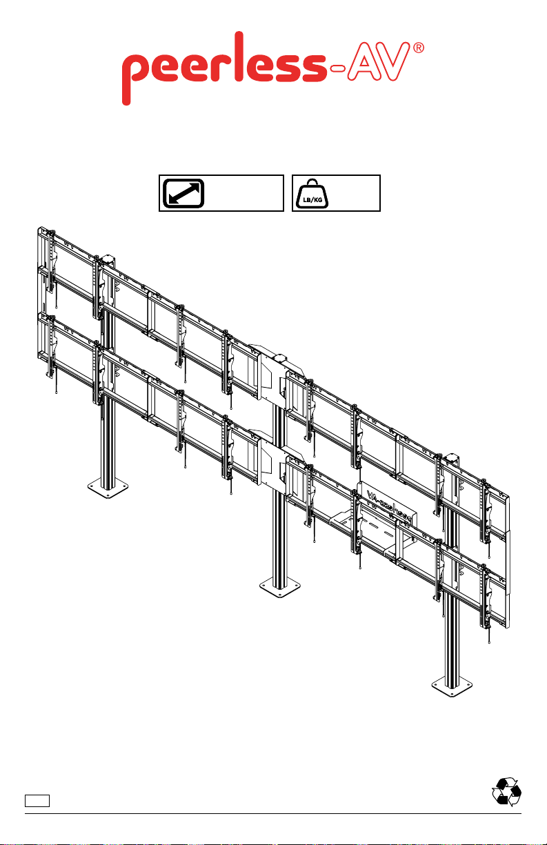
DS-S555-4X2
46" - 55"
(117 - 140 cm)
MAX
800 lb
(363 kg)
ENG
1
2014-07-29 #:009-9090-4 (2018-03-08)
Page 2
WARNING
ENG - Do not begin to install product until you have read and understood the instructions and warnings
contained in this user guide. Always use an assistant or mechanical lifting equipment to safely lift and position
equipment. This product must be installed onto at, hard, level surface to prevent tipping. Use with heavier
displays may result in instability causing tip over resulting in death or serious injury. Displays must be removed
before moving cart. Not recommended for use in areas with heavy trafc. This product is intended for indoor use
only. Use of this product outdoors could lead to product failure or personal injury. Screws must be tightly secured.
Do not overtighten screws or damage can occur and product may fail. Never exceed the Maximum Load
Capacity. Be careful not to pinch ngers when operating the mount. Death or serious injury may occur when
children climb on audio and/or video equipment furniture. A remote control or toys placed on the furnishing may
encourage a child to climb on the furnishing and as a result the furnishing may tip over on to the child. Relocating
audio and/or video equipment to furniture not specically designed to support audio and/or video equipment may
result in death or serious injury due to the furnishing collapsing or over turning onto a child. For support please
call customer care at 1-800-865-2112.
ENG
Symbols
ENG
ENG
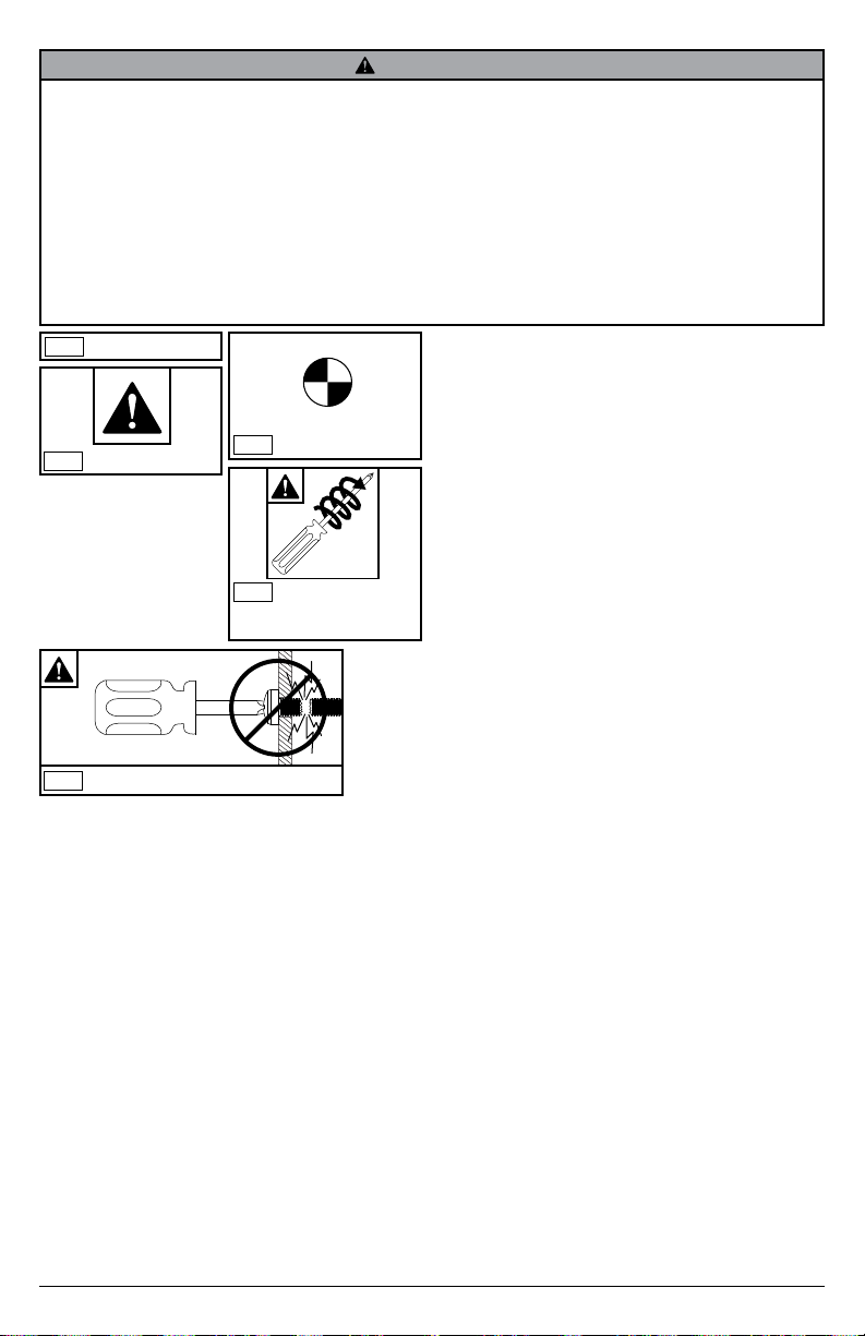
WARNING
Display center.
x3
Screws must get at
ENG
least three full turns
and t snug.
ENG
Do not overtighten screws.
2
2014-07-29 #:009-9090-4 (2018-03-08)
Page 3
ENG
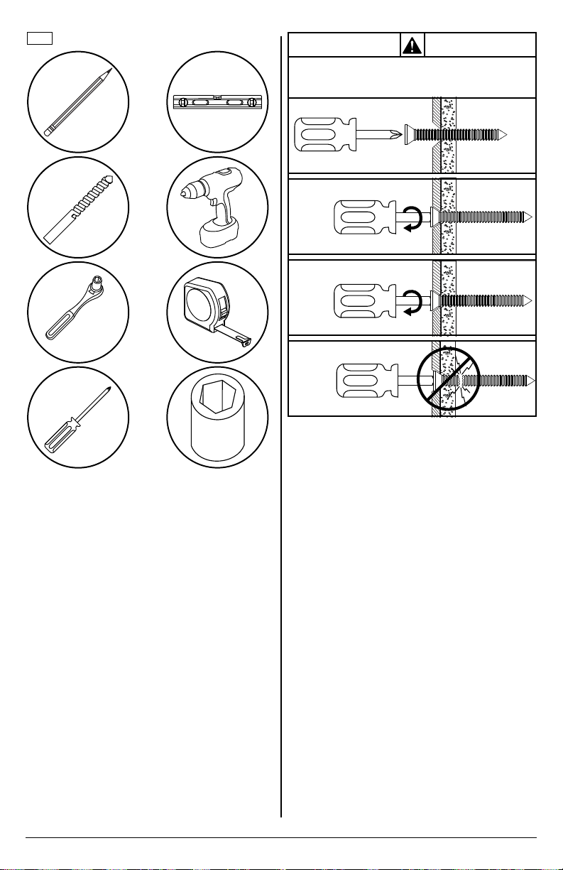
Tools Needed for Assembly.
To properly tighten screws: Tighten until screw
head makes contact, then tighten another 1/2
turn. Do not overtighten screws.
1
3/8"
(10mm)
2
3
+1/2
4
3/8"
(10mm)
3
2014-07-29 #:009-9090-4 (2018-03-08)
Page 4
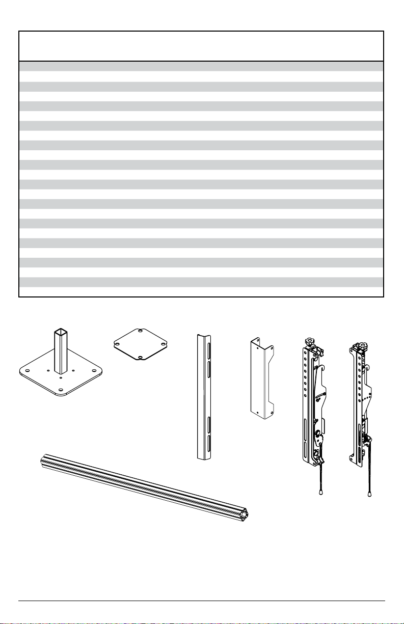
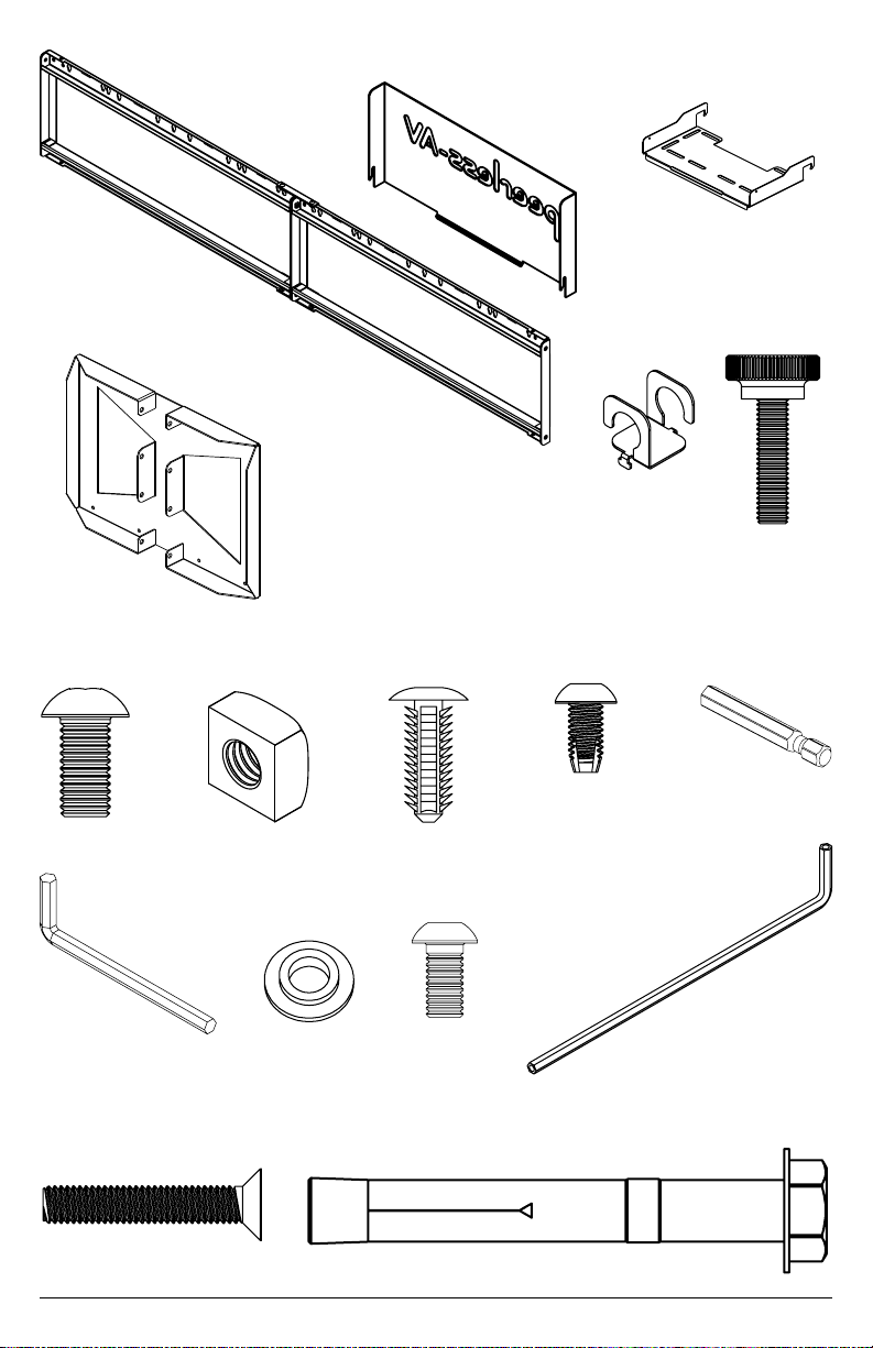
Parts (Before beginning, make sure you have all parts shown below).
Parts List
(8)
Part #Description Qty
G
right adaptor
bracket
A pedestal 3 146-T1132
B column 3 146-T1131
C cover 3 145-T1809
D side support bracket 2 145-T1807
E vertical support bracket 4 145-T1806
F left adaptor bracket 8 146-1609
G right adaptor bracket 8 146-1608
H computer cover 1 145-T1930
I computer shelf 1 145-T1931
J dual cross support 4 146-T1905
K cord bracket 6 146-T1321
L knob 6 560-1160
M bracket, 4x2 conguration 2 145-T1858
N M8 x 16mm socket button screw 84 520-9527
O M8 square nut 36 530-1066
P cover clip 12 590-0317
Q M5 x 10mm type-f, socket pin screw 18 520-1164
R 1/4" power bit 1 560-0263
S 5mm allen wrench 1 560-9640
T nylon shoulder washer 32 590-2233
U M6 x 12mm socket pin screw 32 520-1050
V 4mm allen wrench 1 560-9646
W M6 x 35mm screw 12 520-0717
X rawl bolt #6913 12 5M9-381-H03
(3)
A
pedestal
C
(3)
cover
(2)
D
side support
bracket
(4)
E
vertical support
bracket
F
left adaptor
bracket
(8)
B
column
(3)
4
2014-07-29 #:009-9090-4 (2018-03-08)
Page 5
(4)
J
dual cross
support
(1)
H
computer cover
(1)
I
computer shelf
(84)
N
M8 x 16mm
S
5mm allen
M
bracket, 4x2
conguration
(1)
wrench
(2)
M8 square nut
O
(36)
T (32)
nylon shoulder
washer
(12)
P
cover clip
U (32)
M6 x 12mm
(18)
Q
M5 x 10mm
K
cord
bracket
(6)
V (1)
4mm allen
wrench
(6)
L
knob
(1)
R
1/4" power
bit
(12)
W
M6 x 35mm
(12)
X
rawl bolt
5
2014-07-29 #:009-9090-4 (2018-03-08)
Page 6
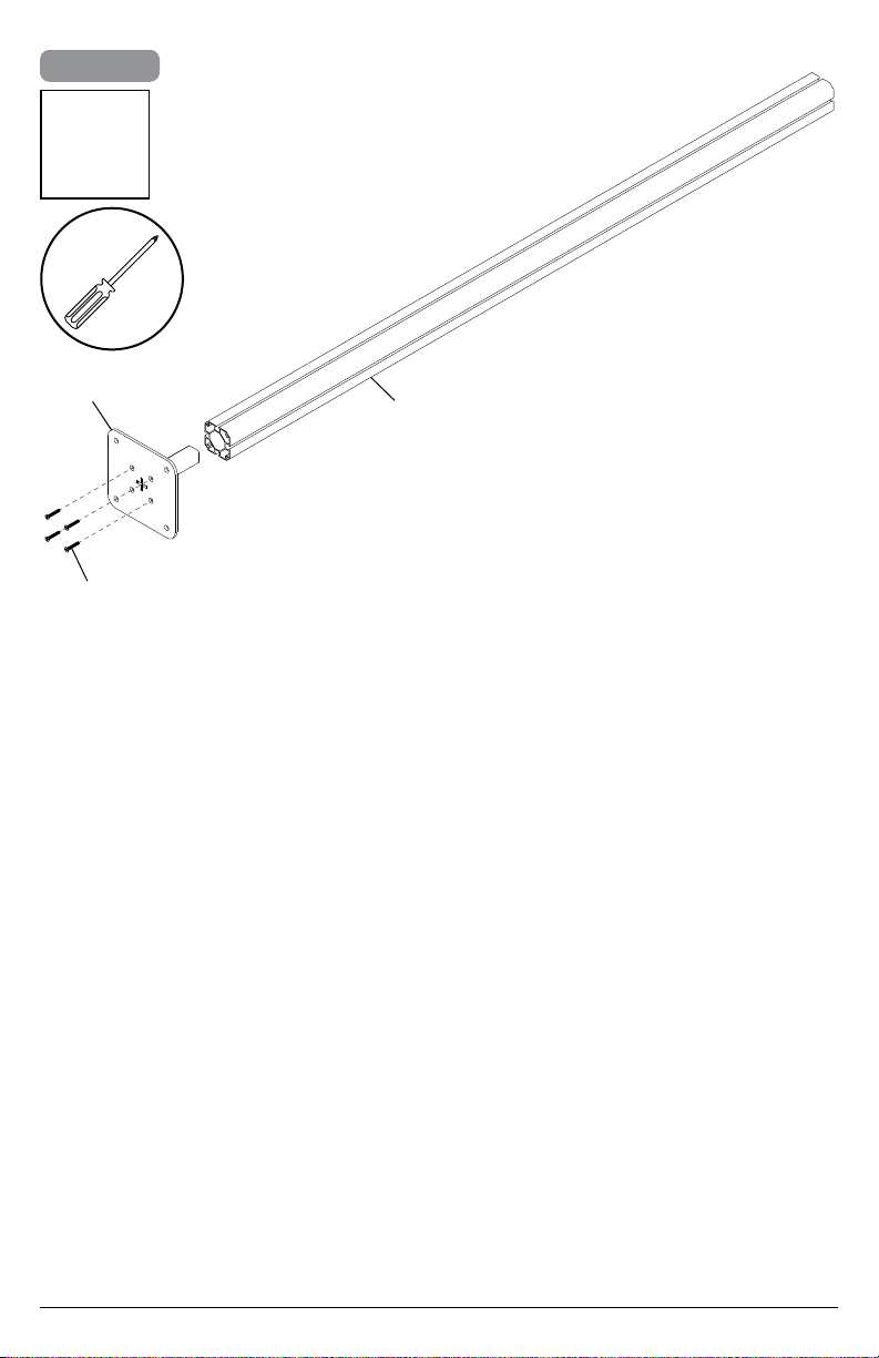
1
x3
A
W (4)
B
6
2014-07-29 #:009-9090-4 (2018-03-08)
Page 7
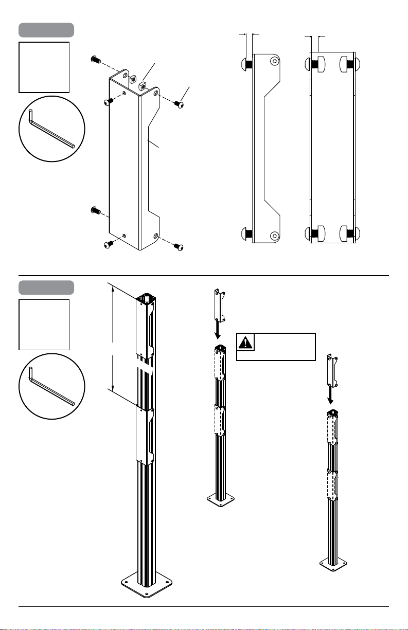
2-1
x4
2-2
S
O (4)
E
N (6)
1/8"
(3mm)
1/8"
(3mm)
x2
S
DISPLAY HEIGHT
TIGHTEN
CONNECTING
HARDWARE
7
2014-07-29 #:009-9090-4 (2018-03-08)
Page 8
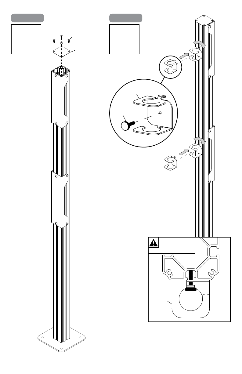
3-1
3-2
P (4)
x2x2
C
K (2)
L (2)
TIGHTEN
CONNECTING
HARDWARE
K
8
2014-07-29 #:009-9090-4 (2018-03-08)
L
TOP VIEW
Page 9

4
Use metric formula below and diagram to
right to determine hole pattern required for
center vertical support bracket. Repeat (x2).
All dimensions are metric.
S
x2
a
b
BACK OF DISPLAY
Use the outside mounting holes when…
a x 4 > 4368mm and a x 3 + b < 4318mm
O (8)
M
N (12)
1/8"
(3mm)
Use the inside mounting holes when…
a x 4 > 4098mm and a x 3 + b < 4064mm
O (8)
M
N (12)
SIDE
BACK
9
2014-07-29 #:009-9090-4 (2018-03-08)
Page 10

5
WARNING
ENG - When installing Peerless mounts on a concrete oor, the oor must be at least 8" thick with a minimum
compressive strength of 2000 psi. Never attach concrete expansion anchors to concrete covered with plaster,
drywall, or other nishing material.
ADVERTENCIA
ESP - Cuando vaya a instalar soportes de techo de Peerless en techos de concreto, los techos tienen que
tener, por lo menos, 8" de grosor con una resistencia a la compresión de 2000 psi como mínimo. Nunca je los
anclajes de expansión para concreto a supercies de concreto recubiertas con yeso, yeso-cartón u otro material
de acabado.
ADVERTISSEMENT
FRN - Lors de l’installation de supports de plafond Peerless sur un plafond en béton, celui-ci doit avoir au moins
8 po (20 cm) d'épaisseur et une résistance à la compression d'au moins 2 000 psi. Ne xez jamais des chevilles
à expansion pour béton à du béton recouvert d’une couche de plâtre, d’une cloison sèche ou de tout autre
matériau de nition.
ACHTUNG
DEU - Werden Peerless-Deckenhalter an einer Betondecke angebracht, so muss deren Dicke mindestens 203
mm (8 Zoll) und ihre Druckfestigkeit mindestens 13,8 N/mm2 (2000 psi) betragen. Betonspreizdübel dürfen
auf keinen Fall an Beton befestigt werden, der mit Verputz, Trockenwand- oder anderem Deckschichtmaterial
bedeckt ist.
WAARSCHUWING
NEL - Als de Peerless-plafondbevestiging op een betonnen plafond wordt geïnstalleerd, moet dit plafond een
dikte van ten minste 20 cm hebben en een druksterkte van ten minste 2000 psi. Gebruik nooit expansie-ankers
voor beton bij installatie op een betonnen plafond bedekt met gips, gipsplaat of ander afwerkingsmateriaal.
AVVERTENZA
ITL - In sede d’installazione dei sostegni Peerless su un softto in calcestruzzo solido, il softto deve avere
uno spessore minimo di 20 cm, con una resistenza alla compressione di almeno 2000 psi (140 kg/cm2). Non
attaccare mai ancoranti a espansione per calcestruzzo su calcestruzzo ricoperto con intonaco, cartongesso o
altro materiale di nitura.
VÝSTRAHA
ČEŠ - Při instalaci stropních držáků Peerless na betonový strop musí být tento trop hrubý minimálně 20 cm s
minimální pevností v tlaku 2000 psi. Expanzní kotvy do betonu nikdy nepřipojujte do betonu pokrytého omítkou,
sádrokartonem nebo jiným dokončovacím materiálem.
VÝSTRAHA
SLK - Pri montáži stropných držiakov Peerless na betónový strop musí mať tento strop hrúbku minimálne 20 cm
s minimálnou tlakovou pevnosťou 2000 psi. Expanzné kotvy do betónu nikdy nenasadzujte do betónu pokrytého
omietkou, sadrokartónom či iným nalizačným materiálom.
AVISO
POR - Ao instalar os suportes para o teto Peerless em tetos de betão, o teto deve ter, no mínimo, 203 mm de
espessura e uma força de compressão mínima de 2000 psi. Nunca instale âncoras de expansão para betão em
superfícies cobertas com estuque, gesso ou outros materiais de acabamento.
UYARI
TÜR - Peerless tavan kaidelerini beton duvara monte ettiğinizde, tavan en azından 2000 psi asgari basınç
dayanımına sahip olmalı ve kalınlığı da en azından 8" olmalıdır. Beton dübelleri hiç bir zaman alçı, alçıpan veya
başka bir bitirme materyali ile kaplı betona takmayınız.
10
2014-07-29 #:009-9090-4 (2018-03-08)
Page 11

4
5-1
ENG
Align base. Mark mounting holes.
5-2
ENG
Drill mounting holes into
supporting surface
(3" (76mm) minimum
depth required).
3/8"
(10mm)
55.00"
(1397mm)
5-3
3/8"
(10mm)
ENG
Align base. Install using concrete anchors
provided.
3/8"
(10mm)
ENG
Tighten.
X (12)
55.00"
(1397mm)
3"
(76mm)
55.00"
(1397mm)
ENG
Maximum 35 ft • lb (47 N.M.).
11
55.00"
(1397mm)
2014-07-29 #:009-9090-4 (2018-03-08)
Page 12

6-1
J (2)
TIGHTEN
CONNECTING
HARDWARE
S
6-2
J (2)
TIGHTEN
CONNECTING
HARDWARE
12
S
2014-07-29 #:009-9090-4 (2018-03-08)
Page 13

7
D (2)
S
O (4)
N (2)
D
N (4)
O (2)
13
2014-07-29 #:009-9090-4 (2018-03-08)
Page 14

8-1
x8
ENG
Center adapter brackets
vertically on back of screen.
8-2
x8
F
X
G
X
SV
F
G
T U
N
OR
x3
14
2014-07-29 #:009-9090-4 (2018-03-08)
Page 15

9-1
Must hang displays to bottom row rst; Secure pin
in "locked" position.
"LOCKED"
POSITION
9-2
Must hang displays on top row last; Secure pin
in "locked" position.
15
"LOCKED"
POSITION
2014-07-29 #:009-9090-4 (2018-03-08)
Page 16

9-3
Must hang displays on top row second; Secure pin
in "locked" position.
OPTIONAL: Insert M5 x 10mm type-F socket pin screws
(Q) to lock latches.
V
Q
x16
"LOCKED"
POSITION
16
2014-07-29 #:009-9090-4 (2018-03-08)
Page 17

Display Adjustment
IN
OUT
TILT FORWARD
SIDE
TILT BACKWARD
SIDE
SIDE
TILT RIGHT
TOP
SIDE
TILT LEFT
TOP
UP DOWN
ROTATE LEFT ROTATE RIGHT
17
2014-07-29 #:009-9090-4 (2018-03-08)
Page 18

10
I
18
2014-07-29 #:009-9090-4 (2018-03-08)
Page 19

11-1
V
11-2
V
1/8"
(3mm)
I
Q (2)
H
I
TIGHTEN
CONNECTING
HARDWARE
19
2014-07-29 #:009-9090-4 (2018-03-08)
Page 20

12
Route cables through cord brackets.
K
K
20
2014-07-29 #:009-9090-4 (2018-03-08)
Page 21

This page intentionally left blank.
21
2014-07-29 #:009-9090-4 (2018-03-08)
Page 22

This page intentionally left blank.
22
2014-07-29 #:009-9090-4 (2018-03-08)
Page 23

Peerless Industries, Inc. (“Peerless”) warrants to original end-users of Peerless® products will be free from defects in material and
LIMITED FIVE-YEAR WARRANTY
workmanship, under normal use, for a period of ve years from the date of purchase by the original end-user (but in no case longer than
six years after the date of the product's manufacture). At its option, Peerless will repair or replace, or refund the purchase price of, any
product which fails to conform with this warranty.
In no event shall the duration of any implied warranty of merchantability or tness for a particular purpose be longer than the
period of the applicable express warranty set forth above. Some states do not allow limitations on how long a implied warranty lasts,
so the above limitation may not apply to you.
This warranty does not cover damage caused by (a) service or repairs by the customer or a person who is not authorized for such service
or repairs by Peerless, (b) the failure to utilize proper packing when returning the product, (c) incorrect installation or the failure to follow
Peerless' instructions or warnings when installing, using or storing the product, or (d) misuse or accident, in transit or otherwise, including
in cases of third party actions and force majeure.
In no event shall Peerless be liable for incidental or consequential damages or damages arising from the theft of any product,
whether or not secured by a security device which may be included with the Peerless
exclusion or limitation of incidental or consequential damages, so the above limitation or exclusion may not apply to you.
This warranty is in lieu of all other warranties, expressed or implied, and is the sole remedy with respect to product defects. No dealer,
distributor, installer or other person is authorized to modify or extend this Limited Warranty or impose any obligation on Peerless in
connection with the sale of any Peerless
This warranty gives specic legal rights, and you may also have other rights which vary from state to state.
®
product.
®
product. Some states do not allow the
23
2014-07-29 #:009-9090-4 (2018-03-08)
Page 24

Peerless-AV
2300 White Oak Circle
Aurora, IL 60502
Email: tech@peerlessmounts.com
Ph: (800) 865-2112
Fax: (800) 359-6500
www.peerless-av.com
© 2018, Peerless Industries, Inc.
Peerless-AV Europe
Unit 3 Watford Interchange,
Colonial Way, Watford, Herts,
WD24 4WP, United Kingdom
Customer Care
44 (0) 1923 200 100
www.peerless-av.com
© 2018, Peerless Industries, Inc.
Peerless-AV de Mexico
Ave de las Industrias 413
Parque Industrial Escobedo
Escobedo N.L Mexico 66062
Servicio al Cliente
01-800-849-65-77
www.peerless-av.com
© 2018, Peerless Industries, Inc.
 Loading...