

Page 1
DS-LEDP
Series
ENG
*Actual confi guration may vary
1
2017-02-13 #:146-9011-4 (2018-03-02)
Page 2
WARNING
ENG - This product is designed to be installed on unistruts. Before installing make sure the supporting surface
will support the combined load of the equipment and hardware. Screws must be tightly secured. Do not
overtighten screws or damage can occur and product may fail. Never exceed the Maximum Load Capacity.
Always use an assistant or mechanical lifting equipment to safely lift and position equipment. This product is
intended for indoor use only. Use of this product outdoors could lead to product failure or personal injury. Be
careful not to pinch fi ngers when operating the mount. For support please call customer care at 1-800-865-2112.
ENG
ENG
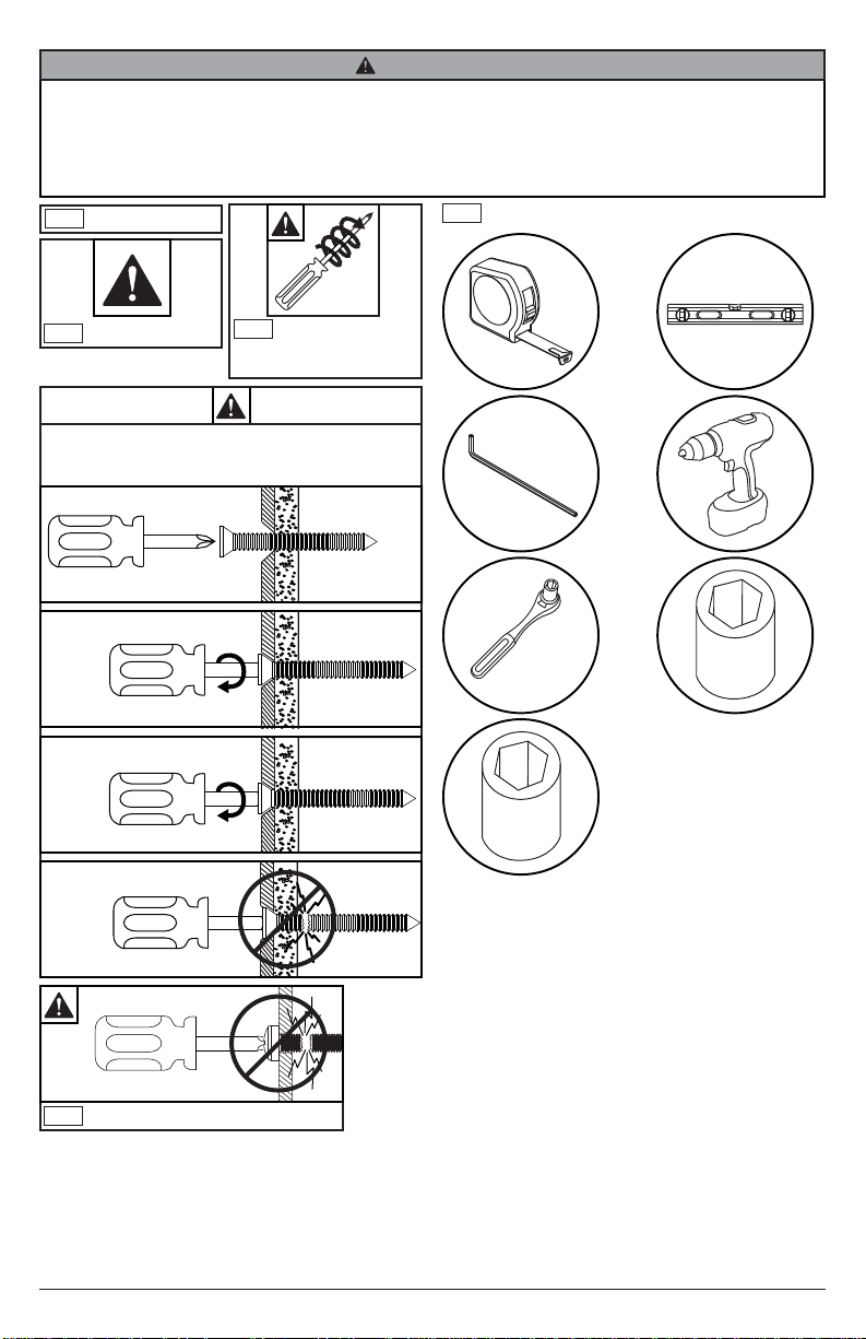
Symbols
Tools Needed for Assembly.
x3
Screws must get at
ENG
WARNING
ENG
least three full turns
and fi t snug.
To properly tighten screws: Tighten until screw
head makes contact, then tighten another 1/2
turn. Do not overtighten screws.
1
2
3
+1/2
4
4mm
7/16"
(11mm)
5/16"
(8mm)
ENG
Do not overtighten screws.
2
2017-02-13 #:146-9011-4 (2018-03-02)
Page 3
ENG
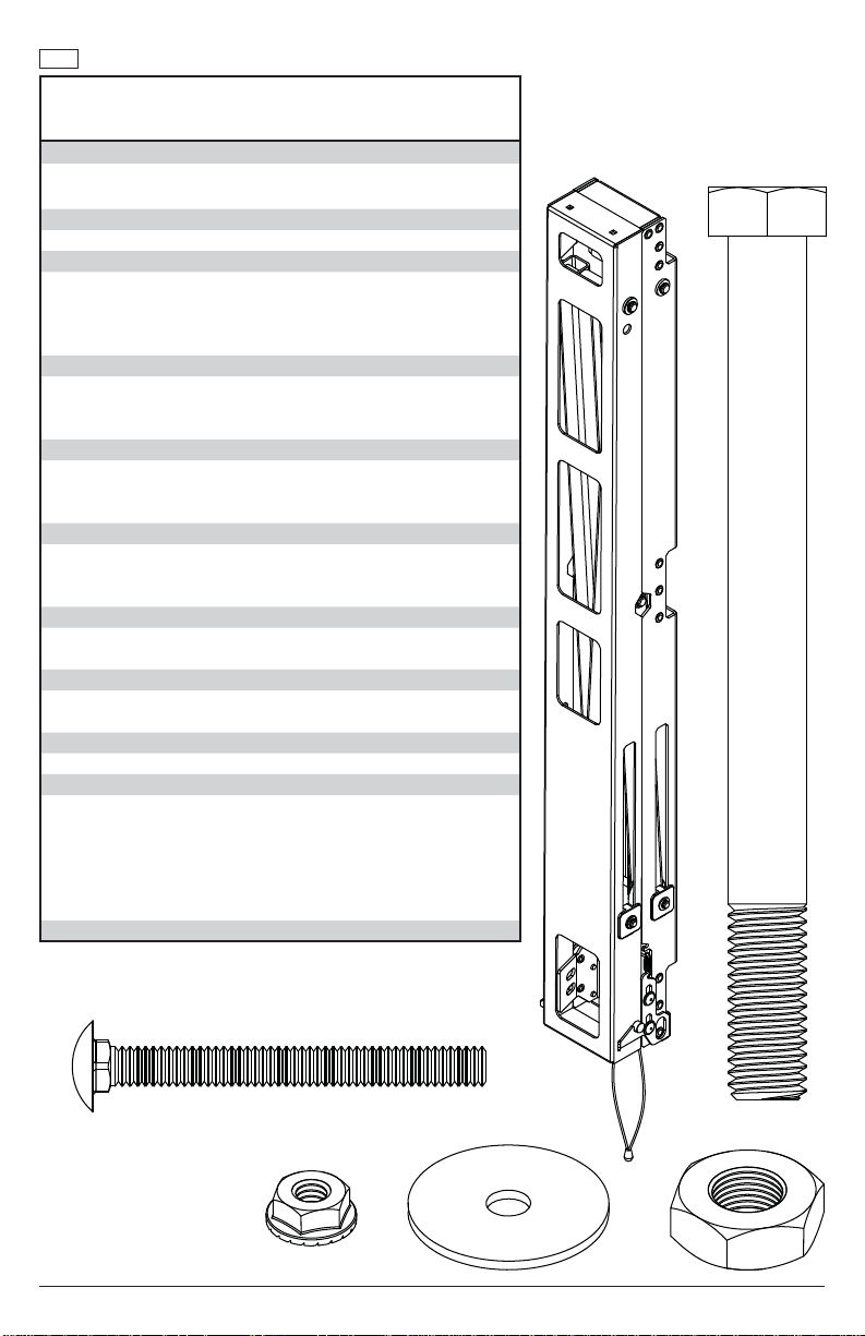
Parts (Before beginning, make sure you have all parts shown below).
Parts List
A corner bracket kit KIT-LED001-2
corner bracket asy 1
wood screw 1
B extrusion connector kit KIT-LED004A-2
extrusion connector asy 1
C corner adaptor kit KIT-LEDADP-XXXA-2
top corner bracket asy 2
bottom corner bracket asy 2
screw 4
washer (optional) 4
D side adaptor kit KIT-LEDADP-XXXB-2
outer bracket 1
screw 1
washer (optional) 1
E top center adaptor kit KIT-LEDADP-XXXC-2
top center bracket asy 1
screw 2
washer (optional) 2
F bottom center adaptor kit KIT-LEDADP-XXXD-2
bottom center bracket 1
screw 2
washer 2
G horizontal spacer kit KIT-LEDSPR-XXX
outside spacer 2
inside spacer 2
H cross tube support bracket kit KIT-LED006-2
hook bracket asy 2
self drilling screw 2
I tube kit KIT-LEDTUBE-XXX
tube 2
J scissor mechanism kit KIT-LED007
scissor mechanism 1
1/4"-20 x 2.5" carriage bolt 4
fender washer 4
1/4"-20 locknut 4
1/2"-13 x 5.5" screw 1
1/2"-13 hex nut 1
K extrusion kit KIT-LEDEXTXXX
Part #Description Qty
J
scissor
mechanism kit
3
2017-02-13 #:146-9011-4 (2018-03-02)
Page 4
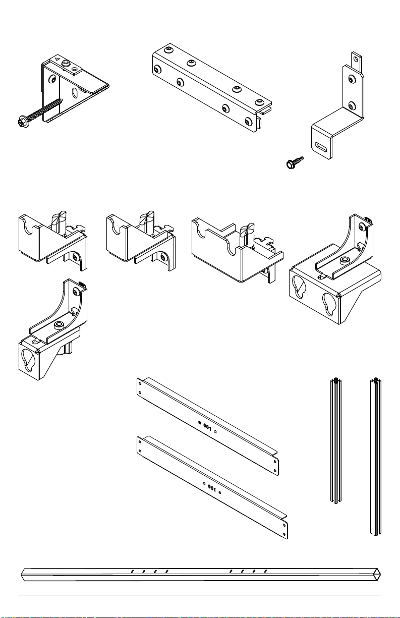
A
corner bracket
kit
B
extrusion
connector kit
H
cross tube
support bracket kit
C
corner adaptor
kit
D
side adaptor kit
top center
adaptor kit
G
horizontal
spacer kit
E
F
bottom center
adaptor kit
K
extrusion kit
I
tube kit
4
2017-02-13 #:146-9011-4 (2018-03-02)
Page 5
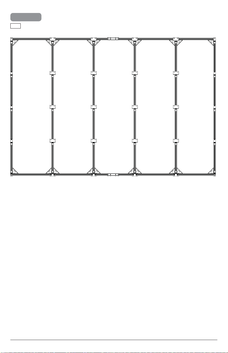
1
ENG
Refer to layout drawing included for your
specifi c model.
5
2017-02-13 #:146-9011-4 (2018-03-02)
Page 6
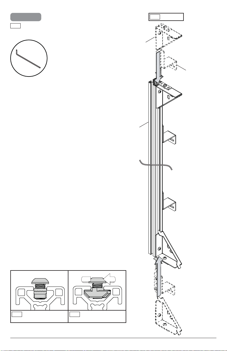
2-1
ENG
Insert corner brackets and support brackets into
extrusion and tighten screw to lock channel nut in
place.
4mm
A (2)
K
ENG
Left column
H (2)
ENG
Channel nut must start
in vertical position.
ENG
Tighten screw to lock
channel nut.
6
2017-02-13 #:146-9011-4 (2018-03-02)
Page 7
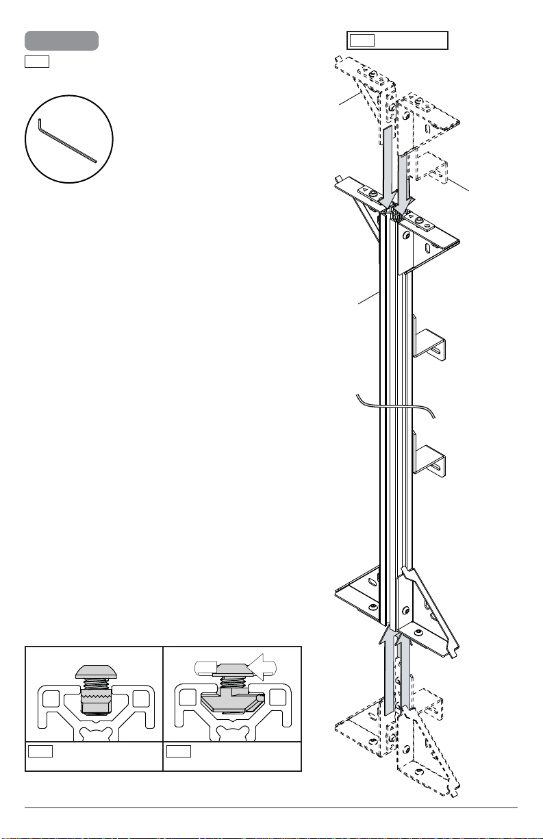
2-2
ENG
Insert corner brackets and support brackets into
extrusion and tighten screw to lock channel nut in
place.
4mm
A (4)
ENG
K
Middle columns
H (2)
ENG
Channel nut must start
in vertical position.
ENG
Tighten screw to lock
channel nut.
7
2017-02-13 #:146-9011-4 (2018-03-02)
Page 8
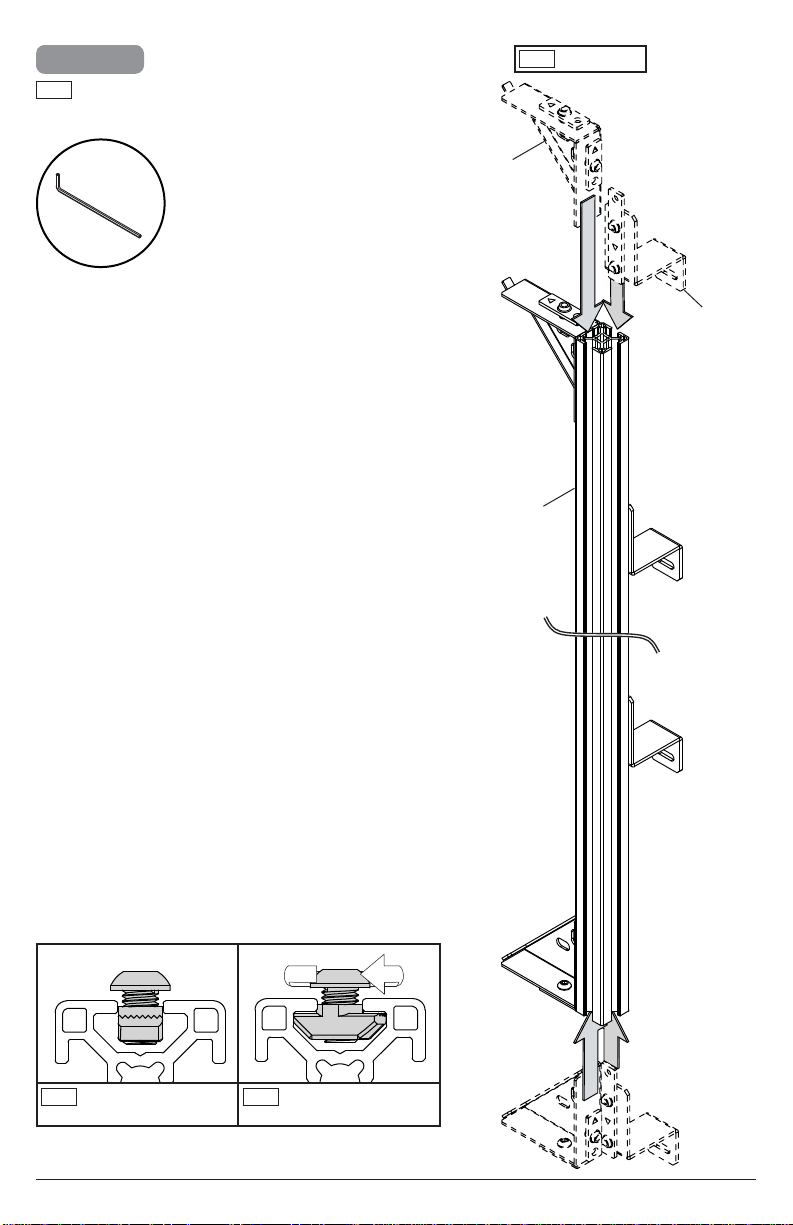
2-3
ENG
Insert corner brackets and support brackets into
extrusion and tighten screw to lock channel nut in
place.
ENG
Right column
4mm
A (2)
H (2)
K
ENG
Channel nut must start
in vertical position.
ENG
Tighten screw to lock
channel nut.
8
2017-02-13 #:146-9011-4 (2018-03-02)
Page 9
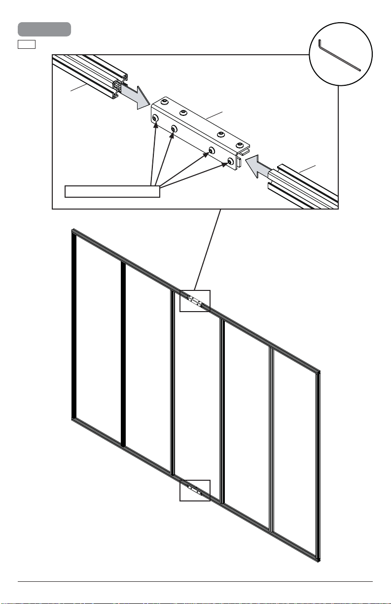
3
ENG
Optional: Use extrusion connector if provided.
K
Tighten connecting hardware.
4mm
B
K
9
2017-02-13 #:146-9011-4 (2018-03-02)
Page 10

4-1
ENG
Secure right vertical column onto both horizontal
columns.
4mm
K
10
ENG
Tighten corner bracket hardware.
2017-02-13 #:146-9011-4 (2018-03-02)
Page 11

4-2
ENG
Slide on columns, spacing and securing one at
a time.
ENG
Outside spacer (G)
ENG
Inside spacer (G)
G
ENG
Tighten corner bracket hardware.
11
4mm
2017-02-13 #:146-9011-4 (2018-03-02)
Page 12

5-1
ENG
Insert adaptors into extrusion and tighten screws to
lock channel nuts in place. Refer to layout drawing
included with your model for appropriate spacing.
4mm
ENG
Channel nut must start
in vertical position.
C
D
D
D D
C
E
E
E
E
F
ENG
Tighten screw to lock
channel nut.
C
D
D
C
12
2017-02-13 #:146-9011-4 (2018-03-02)
Page 13

5-2
ENG
Adjust adaptor and support bracket height.
Refer to layout drawing included for
appropriate spacing.
x
z
x
ENG
L bracket must be fl ush
with bottom of extrusion.
13
x
z
y
2017-02-13 #:146-9011-4 (2018-03-02)
Page 14

5-3
ENG
Tighten all adaptor bracket and support bracket
hardware.
4mm
14
2017-02-13 #:146-9011-4 (2018-03-02)
Page 15

6
ENG
Fully extend and bolt into place for installation only.
Unbolt and close after installation.
J
ENG
Hand tighten.
J (2)
15
2017-02-13 #:146-9011-4 (2018-03-02)
Page 16

7
WARNING
ENG - When installing Peerless wall mounts to P1000T unistrut metal framing channels, the channels must be
installed and supported per the Unistrut design specifi cations. Use only compatible Unistrut hardware. Never
exceed maximum load capacity of Unistrut channel or supporting surface.
7-1
ENG
Unistrut not included. Refer to layout
drawing included with your model for
appropropriate spacing.
21"
(533mm)
7/8"
(22mm)
13/16"
(21mm)
ENG
Low profi le preferred
(76mm)
9/32"
(7mm)
1 - 5/8"
(41mm)
(22mm)
ENG
Low profi le: 5/16-18 (M8) spring nut for 13/16" channel (14)
ENG
Standard profi le: 5/16-18 (M8) spring nut for 1-5/8" channel (14)
9/32"
(7mm)
7/8"
1 - 5/8"
(41mm)
Standard profi le optional
1 - 5/8"
(41mm)
x
3"
3"
(76mm)
24.375"
(619mm)
Low profi le: P1000T 1-5/8" x 13/16" Unistrut steel framing channel
ENG
Standard profi le: P1000T 1-5/8" x 1-5/8" Unistrut steel framing channel
16
2017-02-13 #:146-9011-4 (2018-03-02)
Page 17

7-2
4mm
ENG
Unistrut hardware not
included.
7-3
4mm
1/4"
(6mm)
Low profi le: 5/16-18 x 3/4" (M8 x 20mm) bolt
ENG
Standard profi le: 5/16-18 x 3/4" (M8 x 20mm) bolt
J (2)
17
2017-02-13 #:146-9011-4 (2018-03-02)
Page 18

7-4
4mm
ENG
Unistrut hardware not included. Do not
tighten screws.
Low profi le: 5/16-18 x 3/4" (M8 x 20mm) bolt
ENG
Standard profi le: 5/16-18 x 3/4" (M8 x 20mm) bolt
18
2017-02-13 #:146-9011-4 (2018-03-02)
Page 19

8-1
J
7/16"
(11mm)
I (2)
J
J
I
J
19
2017-02-13 #:146-9011-4 (2018-03-02)
Page 20

8-2
ENG
Level and square components. Tighten
connecting hardware.
ENG
Tighten.
ENG
4mm
7/16"
(11mm)
Tighten.
20
2017-02-13 #:146-9011-4 (2018-03-02)
Page 21

9-1
H
I
21
2017-02-13 #:146-9011-4 (2018-03-02)
Page 22

9-2
5/16"
(8mm)
H
22
2017-02-13 #:146-9011-4 (2018-03-02)
Page 23

10-1
ENG
Use hardware provided with
adaptor kits.
1/4"
(6mm)
10-2
ENG
Level display on Y and X
axis. Tighten connecting
hardware after attaching
each display.
4mm
x3
4mm
23
1
2017-02-13 #:146-9011-4 (2018-03-02)
Page 24

10-3
ENG
Level displays on Y and X
axis. Tighten connecting
hardware after attaching
each display.
4mm
10-4
ENG
Level displays on Y and X
axis. Tighten connecting
hardware after attaching
each display.
2
2
4mm
3
24
3
2017-02-13 #:146-9011-4 (2018-03-02)
Page 25

10-5
ENG
Level displays on Y and X
axis. Tighten connecting
hardware after attaching
each display.
4mm
11
ENG
Optional: loosen screws to
remove screens.
4
4
4mm
1
25
2
3
2
1
2017-02-13 #:146-9011-4 (2018-03-02)
Page 26

12
ENG
Unbolt and close after installation.
ENG
Remove
J (2)
26
2017-02-13 #:146-9011-4 (2018-03-02)
Page 27

Peerless Industries, Inc. (“Peerless”) warrants to original end-users of Peerless® products will be free from defects in material and
LIMITED FIVE-YEAR WARRANTY
workmanship, under normal use, for a period of fi ve years from the date of purchase by the original end-user (but in no case longer than
six years after the date of the product's manufacture). At its option, Peerless will repair or replace, or refund the purchase price of, any
product which fails to conform with this warranty.
In no event shall the duration of any implied warranty of merchantability or fi tness for a particular purpose be longer than the
period of the applicable express warranty set forth above. Some states do not allow limitations on how long a implied warranty lasts,
so the above limitation may not apply to you.
This warranty does not cover damage caused by (a) service or repairs by the customer or a person who is not authorized for such service
or repairs by Peerless, (b) the failure to utilize proper packing when returning the product, (c) incorrect installation or the failure to follow
Peerless' instructions or warnings when installing, using or storing the product, or (d) misuse or accident, in transit or otherwise, including
in cases of third party actions and force majeure.
In no event shall Peerless be liable for incidental or consequential damages or damages arising from the theft of any product,
whether or not secured by a security device which may be included with the Peerless
exclusion or limitation of incidental or consequential damages, so the above limitation or exclusion may not apply to you.
This warranty is in lieu of all other warranties, expressed or implied, and is the sole remedy with respect to product defects. No dealer,
distributor, installer or other person is authorized to modify or extend this Limited Warranty or impose any obligation on Peerless in
connection with the sale of any Peerless
This warranty gives specifi c legal rights, and you may also have other rights which vary from state to state.
®
product.
®
product. Some states do not allow the
27
2017-02-13 #:146-9011-4 (2018-03-02)
Page 28

Peerless-AV
2300 White Oak Circle
Aurora, IL 60502
Email: tech@peerlessmounts.com
Ph: (800) 865-2112
Fax: (800) 359-6500
www.peerless-av.com
© 2018, Peerless Industries, Inc.
Peerless-AV Europe
Unit 3 Watford Interchange,
Colonial Way, Watford, Herts,
WD24 4WP, United Kingdom
Customer Care
44 (0) 1923 200 100
www.peerless-av.com
© 2018, Peerless Industries, Inc.
Peerless-AV de Mexico
Ave de las Industrias 413
Parque Industrial Escobedo
Escobedo N.L Mexico 66062
Servicio al Cliente
01-800-849-65-77
www.peerless-av.com
© 2018, Peerless Industries, Inc.
 Loading...