

Page 1
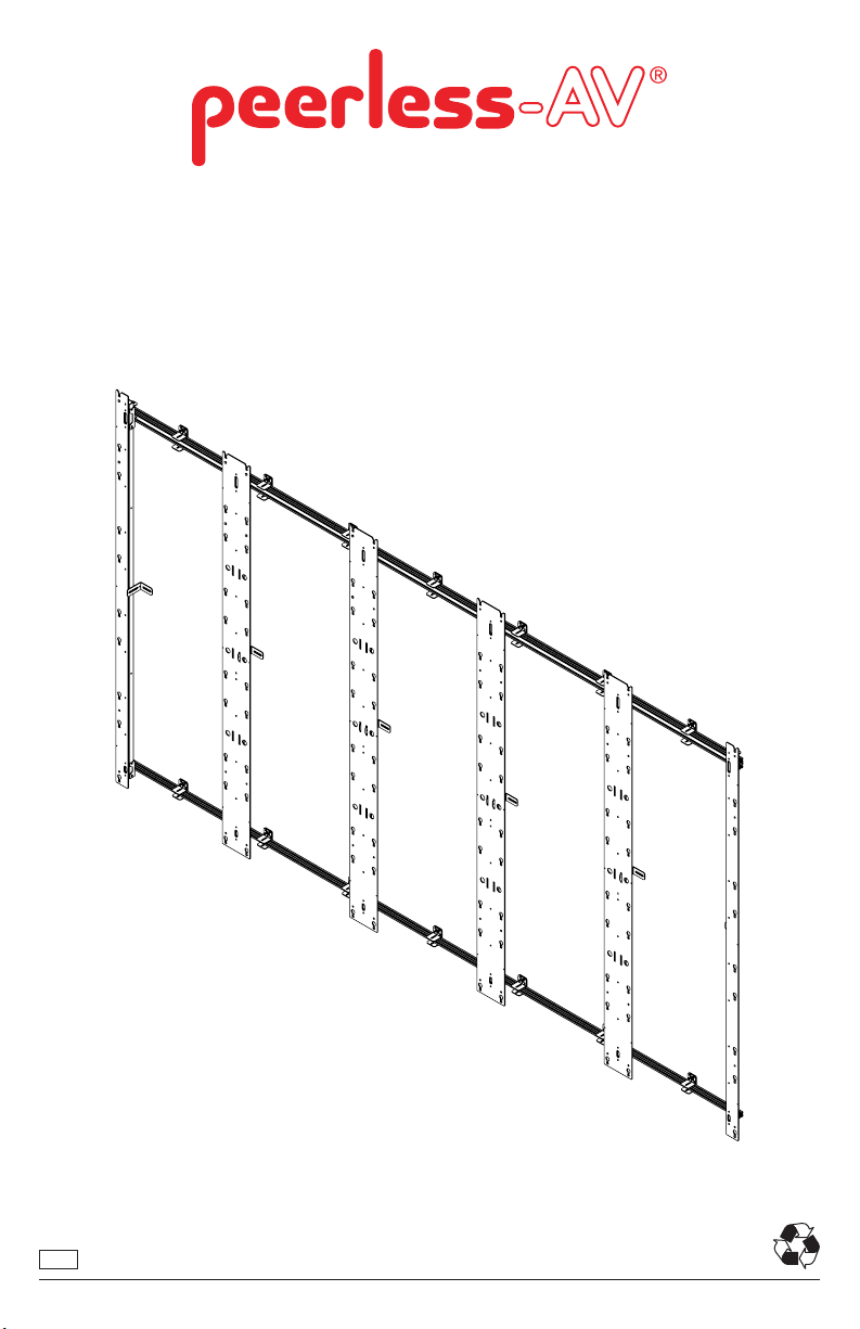
DS-LEDA27 Series
For Absen Acclaim
ENG
*Actual conguration may vary
1
2018-05-15 #:146-9026-4 (2019-08-15)
Page 2
WARNING
ENG - This product is designed to be installed on plywood walls. Hardware is included for plywood installation.
Before installing make sure the supporting surface will support the combined load of the equipment and
hardware. Screws must be tightly secured. Do not overtighten screws or damage can occur and product may fail.
Never exceed the Maximum Load Capacity. Always use an assistant or mechanical lifting equipment to safely lift
and position equipment. This product is intended for indoor use only. Use of this product outdoors could lead to
product failure or personal injury. Be careful not to pinch ngers when operating the mount. For support please
call customer care at 1-800-865-2112.
ENG
ENG
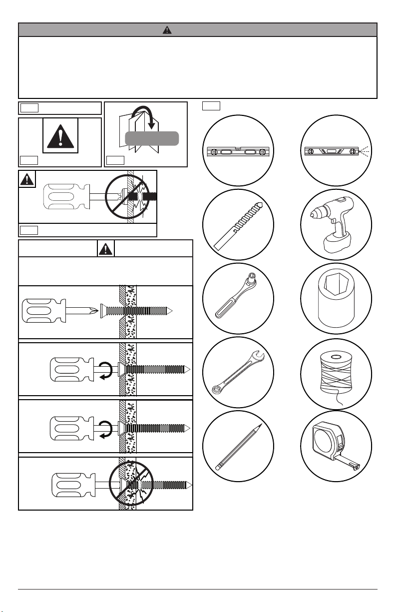
Symbols
Tools Needed for Assembly.
#
ENG
WARNING
ENG
Do not overtighten screws.
To properly tighten screws: Tighten until screw
head makes contact, then tighten another 1/2
turn. Do not overtighten screws.
ENG
Skip to step.
1
2
3
+1/2
5/32"
(4mm)
3/8"
(10mm)
3/8"
(10mm)
4
2
2018-05-15 #:146-9026-4 (2019-08-15)
Page 3
ENG
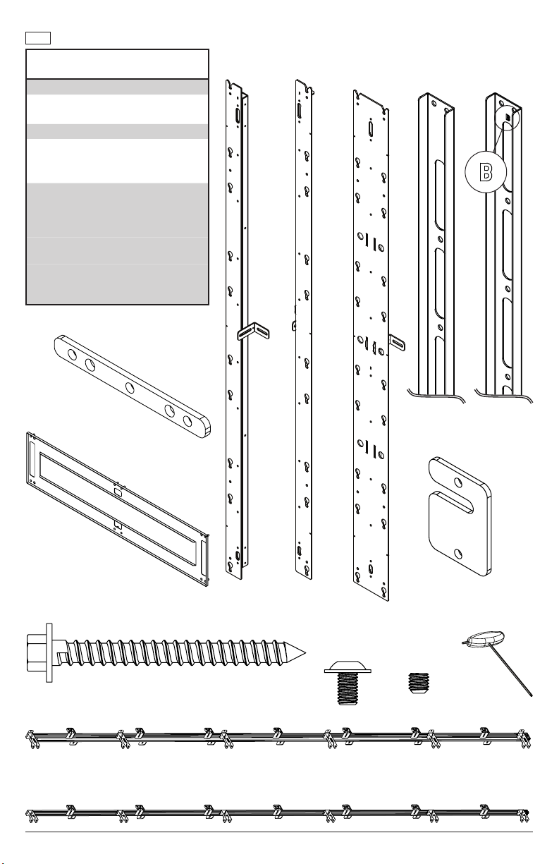
Parts (Before beginning, make sure you have all parts shown below).
Parts List
Description
outside vertical column kit
A1 left column
A2 right column
spacer kit
B1 top vertical spacer
B2 bottom vertical spacer (not used)
B3 horizontal spacer
C inside vertical column kit
D top horizontal extrusion asy
E bottom horizontal extrusion asy
F extrusion connector
G 3mm allen wrench 2-tip t-handle
H M5 x 5mm set screw
I #14 x 2.5" wood screw
J M5 x 8mm socket button screw
K wall plate shim
F
extrusion
connector
B3
horizontal
spacer
A1 A2 C
left column right column inside vertical
column kit
top vertical
spacer
wall plate
bottom vertical
spacer
K
shim
B2B1
D
top horizontal
extrusion asy
E
bottom horizontal
extrusion asy
I
#14 x 2.5"
wood screw
G
3mm allen wrench
two-tip T-handle
J
M5 x 8mm
3
2018-05-15 #:146-9026-4 (2019-08-15)
H
M5 x 5mm
set screw
Page 4
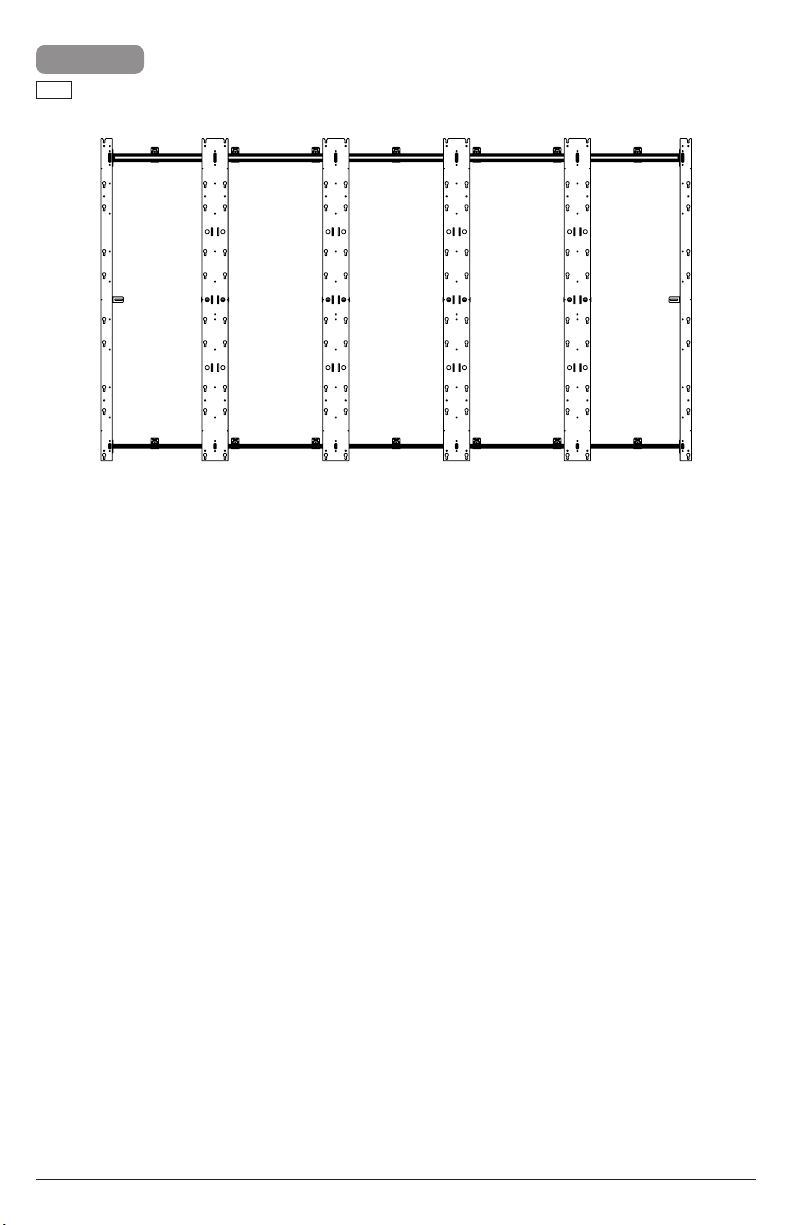
1
ENG
Refer to layout drawing included for your
specic model.
4
2018-05-15 #:146-9026-4 (2019-08-15)
Page 5
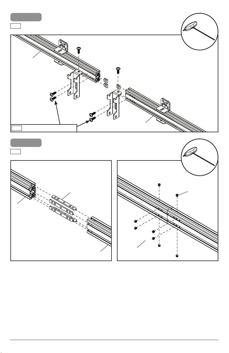
2-1
ENG
Optional: If connecting two top horizontal extrusions,
rst remove inner hook-on brackets.
D
G
ENG
Remove and save hardware.
2-2
ENG
Use extrusion connectors to connect top horizontal
extrusions.
F (4)
D
D
D
G
H (8)
G (4)
5
2018-05-15 #:146-9026-4 (2019-08-15)
Page 6
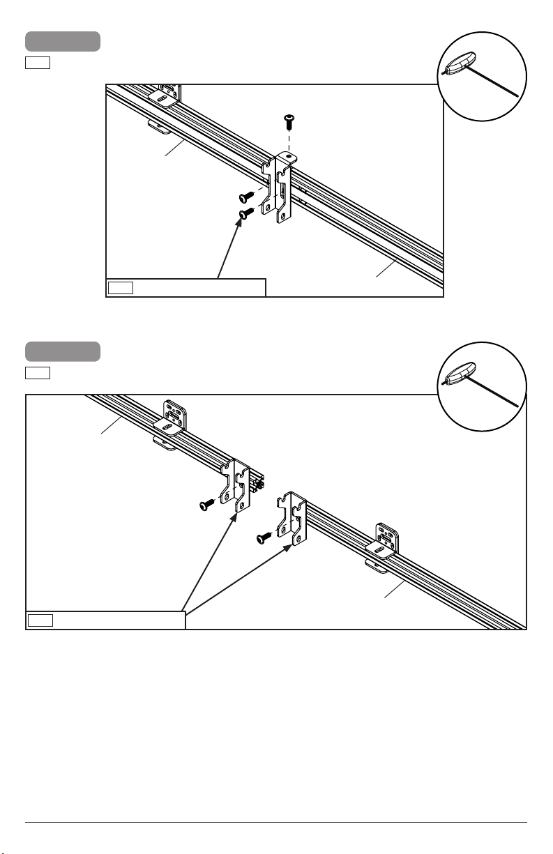
2-3
ENG
Replace one hook-on bracket in between connected
extrusions.
D
G
ENG
Use saved hardware.
3-1
ENG
Optional: If connecting two bottom horizontal
extrusions, rst remove inner hook-on brackets
E
ENG
Remove and save hardware.
D
G
E
6
2018-05-15 #:146-9026-4 (2019-08-15)
Page 7
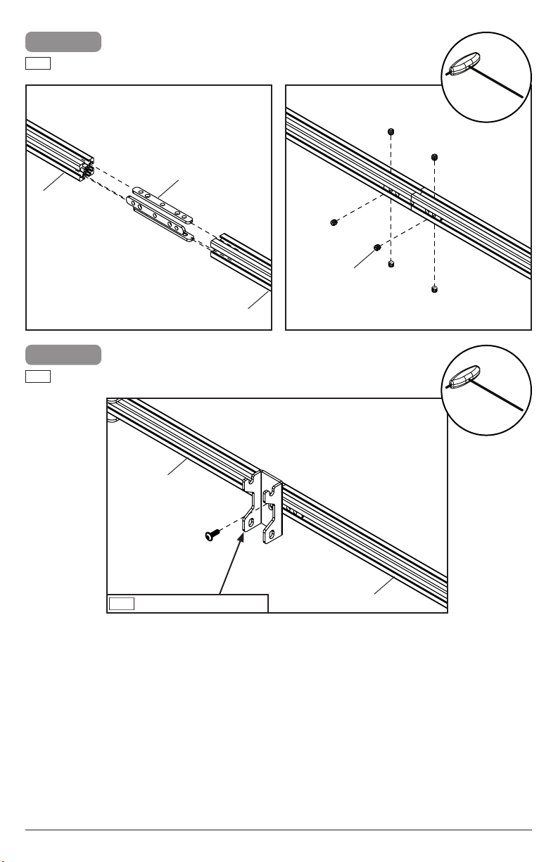
3-2
ENG
Use extrusion connectors to connect bottom
horizontal extrusions.
F (3)
E
3-3
ENG
Replace one hook-on bracket in between connected
extrusions.
G
H (6)
E
G
E
ENG
Use saved hardware.
E
7
2018-05-15 #:146-9026-4 (2019-08-15)
Page 8
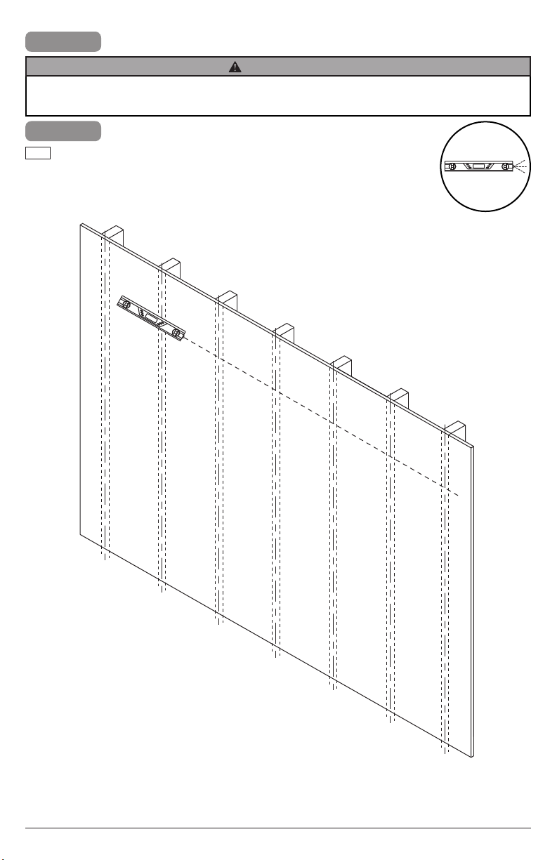
4
WARNING
ENG - When installing Peerless wall mounts on a wood stud wall covered with plywood, verify that the wood
studs are a minimum of 2" x 4" nominal size and plywood is a minimum Grade BC, 1/2" (13 mm) thick. Plywood
may be covered by gypsum board (drywall) up to 5/8" thick.
4-1
ENG
Use a laser level to keep mounting holes
level.
8
2018-05-15 #:146-9026-4 (2019-08-15)
Page 9
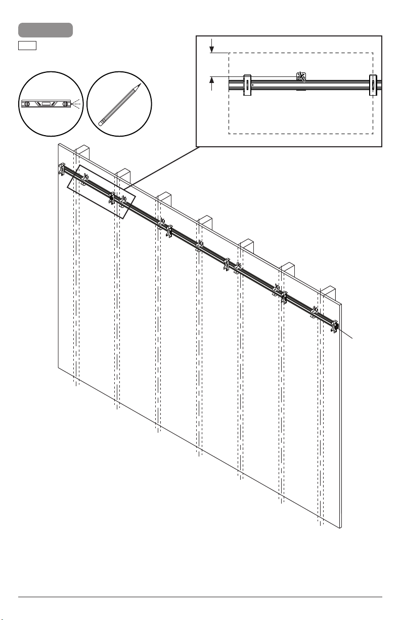
4-2
ENG
Level top horizontal extrusion and mark
mounting holes on plywood (must be
minimum Grade BC, 1/2" (13mm) thick.)
3.94"
(100mm)
display tile
D
9
2018-05-15 #:146-9026-4 (2019-08-15)
Page 10
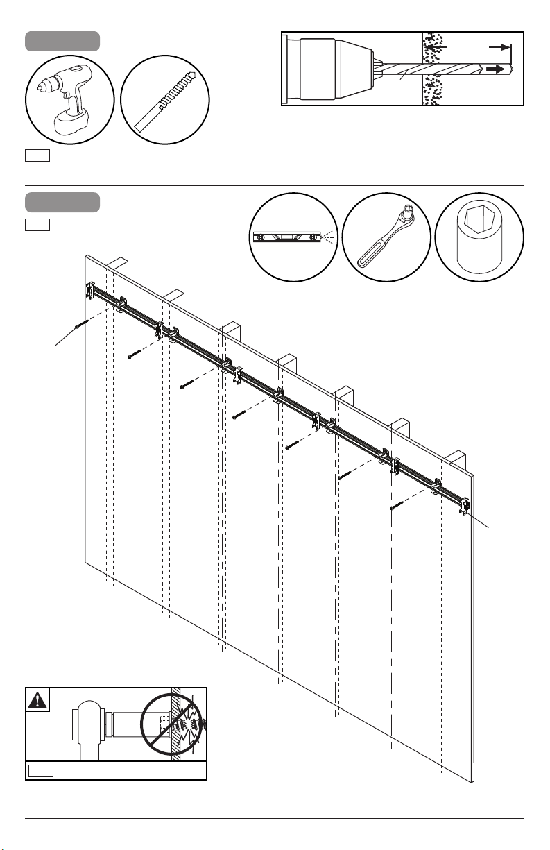
4-3
2.5"
(64mm)
5/32"
(4mm)
ENG
Drill mounting holes into supporting surface
(2.5" (64mm) minimum depth required).
4-4
ENG
Level extrusion. Install using wood screws
provided.
I (7)
5/32"
(4mm)
3/8"
(10mm)
ENG
Maximum 80 in. • lb (9 N.M.).
10
D
2018-05-15 #:146-9026-4 (2019-08-15)
Page 11
4-5
ENG
Secure vertical spacers to the wall ush with the
horizontal extrusion.
3/8"
(10mm)
B1 (2)
ENG
Edges must be ush.
D
B1
I
11
2018-05-15 #:146-9026-4 (2019-08-15)
Page 12

4-6
ENG
Use third vertical spacer to align bottom
horizontal extrusion ush with vertical spacer,
then mark mounting holes on plywood (must be
minimum Grade BC, 1/2" (13mm) thick.)
56.19"
(143cm)
B1
ENG
Edges must be ush.
B1
E
12
E
2018-05-15 #:146-9026-4 (2019-08-15)
Page 13

4-7
2.5"
(64mm)
5/32"
(4mm)
ENG
Drill mounting holes into supporting surface
(2.5" (64mm) minimum depth required).
4-8
ENG
Use third vertical spacer to align bottom
horizontal extrusion ush with vertical
spacer, then install using wood screws
provided.
5/32"
(4mm)
3/8"
(10mm)
I (7)
ENG
Maximum 80 in. • lb (9 N.M.).
13
E
2018-05-15 #:146-9026-4 (2019-08-15)
Page 14

4-9
ENG
Remove vertical spacer.
B1 (2)
3/8"
(10mm)
14
2018-05-15 #:146-9026-4 (2019-08-15)
Page 15

5-1
ENG
Hook on and secure outer vertical columns.
"L" and "R" markings designate left and right
column.
A1
ENG
D
G
Tighten hardware.
J (8)
E
15
A2
2018-05-15 #:146-9026-4 (2019-08-15)
Page 16

5-2
ENG
Hook on and secure all inside vertical
columns.
ENG
Tighten hardware.
G
J (16)
16
C (4)
2018-05-15 #:146-9026-4 (2019-08-15)
Page 17

6-1
ENG
Loosen hardware on vertical columns.
G
17
2018-05-15 #:146-9026-4 (2019-08-15)
Page 18

6-2
ENG
Plumb and level outer columns, then tighten
hardware. Tighten hardware on four corner wall
plates.
ENG
G
Tighten.
18
ENG
Tighten.
2018-05-15 #:146-9026-4 (2019-08-15)
Page 19

6-3
ENG
Tie a string between top slots on outer
columns in order to level the depth of each
vertical column.
ENG
Loosen, adjust, tighten.
G
ENG
Optional leveling for bowed walls
ENG
Loosen.
ENG
Insert.
K
ENG
Tighten.
19
2018-05-15 #:146-9026-4 (2019-08-15)
Page 20

6-4
ENG
Tie a string between bottom slots on outer
columns in order to level the depth of each
vertical column.
G
ENG
Loosen, adjust, tighten.
ENG
Optional leveling for bowed walls
ENG
Loosen.
ENG
Insert.
K
ENG
Tighten.
20
2018-05-15 #:146-9026-4 (2019-08-15)
Page 21

6-5
ENG
With the string still attached, level the height of
each column
G
ENG
Tighten or loosen to adjust height.
21
2018-05-15 #:146-9026-4 (2019-08-15)
Page 22

6-6
ENG
Adjust inner columns to t horizontal spacers.
Tighen column hardware after spacing. Start from
the left column.
G
B3
22
2018-05-15 #:146-9026-4 (2019-08-15)
Page 23

6-7
ENG
Continue adjusting inner columns to t horizontal
spacers until all are level. Tighen column hardware
after spacing
G
B3
23
2018-05-15 #:146-9026-4 (2019-08-15)
Page 24

6-8
ENG
Remove all spacers.
24
2018-05-15 #:146-9026-4 (2019-08-15)
Page 25

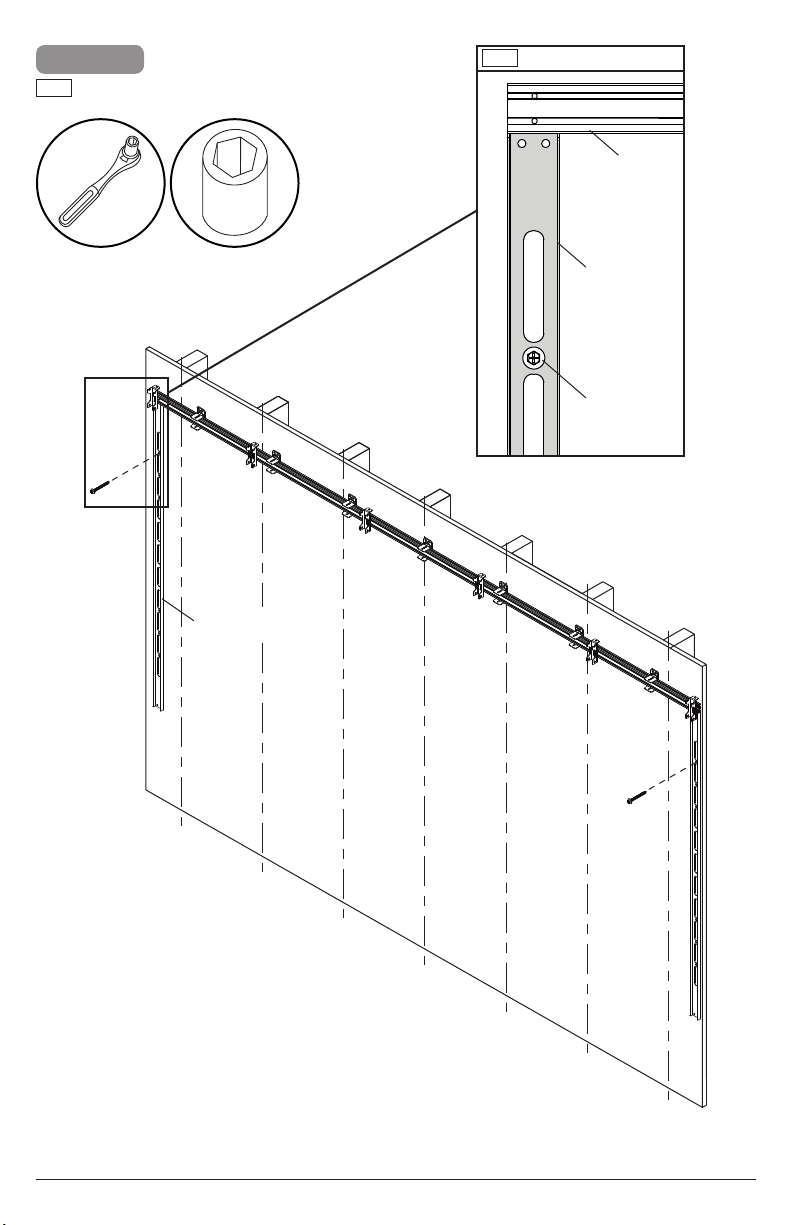
7-1
ENG
Optional: For shallow depth installations, ip wall
bracket orientation as shown.
G
display tile
2.60"
(66mm)
MIN
3.05"
(77mm)
MAX
wall
25
2.25"
(57mm)
MIN
wall
display tile
2.65"
(67mm)
MAX
2018-05-15 #:146-9026-4 (2019-08-15)
Page 26

7-2
ENG
Level L brackets and mark mounting holes
on plywood (must be minimum Grade BC,
1/2" (13mm) thick.)
26
2018-05-15 #:146-9026-4 (2019-08-15)
Page 27

7-3
2.5"
(64mm)
5/32"
(4mm)
ENG
Drill mounting holes into supporting surface
(2.5" (64mm) minimum depth required).
7-4
ENG
Level L brackets. Install using wood
screws provided.
I (10)
5/32"
(4mm)
ENG
Maximum 80 in. • lb (9 N.M.).
3/8"
(10mm)
27
2018-05-15 #:146-9026-4 (2019-08-15)
Page 28

7-5
ENG
Tie a string between center slots on outer column
in order to level the depth of each vertical column.
G
28
2018-05-15 #:146-9026-4 (2019-08-15)
Page 29

7-6
ENG
Adjust depth, then remove string.
ENG
Loosen, adjust, tighten.
G
29
2018-05-15 #:146-9026-4 (2019-08-15)
Page 30

8-1
ENG
Attach display, tighten connecting hardware, and run
cables one at a time starting from the bottom left.
1
3/8"
(10mm)
2
3
30
4
5
2018-05-15 #:146-9026-4 (2019-08-15)
Page 31

8-2
3/8"
(10mm)
21
16
11
6
22
17
12
7
23
18
13
8
24
25
14
15
9
10
31
2018-05-15 #:146-9026-4 (2019-08-15)
Page 32

9
ENG
To remove, start from the top right.
5
3/8"
(10mm)
10
4
9
3
2
8
7
1
32
2018-05-15 #:146-9026-4 (2019-08-15)
Page 33

ENG
This page intentionally left blank.
33
2018-05-15 #:146-9026-4 (2019-08-15)
Page 34

ENG
This page intentionally left blank.
34
2018-05-15 #:146-9026-4 (2019-08-15)
Page 35

Peerless Industries, Inc. (“Peerless-AV”) warrants to original end-users that each Peerless-AV® mounting product will be free from defects
LIMITED FIVE-YEAR WARRANTY
in material and workmanship, under normal use, for the applicable warranty period (from date of the original installation of the product).
At its option, Peerless-AV will repair or replace, or refund the purchase price of, any product which fails to conform with this warranty.
Any implied warranty of merchantability or tness for a particular purpose shall be limited to the period of the
express warranty set forth below.
In no event shall Peerless-AV be liable for incidental or consequential damages, whether or not secured by a
security device which may be included with the product.
Some states do not allow limitations on how long an implied warranty lasts, or the exclusion of incidental or consequential damages, so
the above limitation and/or the above exclusion may not apply to you.
This warranty does not cover damage caused by incorrect selection, installation or the failure to follow Peerless-AV instructions or
warnings when installing, using or storing the product.
This warranty gives specic legal rights, and you may also have other rights which vary from state to state. To make a warranty claim in
North America, contact Peerless-AV customer care at 1-800-865-2112. See complete global warranty information for regions outside North
America at www.peerless-av.com/en-uk/customer-care/warranties-returns.
35
2018-05-15 #:146-9026-4 (2019-08-15)
Page 36

Peerless-AV
2300 White Oak Circle
Aurora, IL 60502
Email: tech@peerlessmounts.com
Ph: (800) 865-2112
Fax: (800) 359-6500
www.peerless-av.com
© 2019, Peerless Industries, Inc.
Peerless-AV Europe
Unit 3 Watford Interchange,
Colonial Way, Watford, Herts,
WD24 4WP, United Kingdom
Customer Care
44 (0) 1923 200 100
www.peerless-av.com
© 2019, Peerless Industries, Inc.
Peerless-AV de Mexico
Ave de las Industrias 413
Parque Industrial Escobedo
Escobedo N.L Mexico 66062
Servicio al Cliente
01-800-849-65-77
www.peerless-av.com
© 2019, Peerless Industries, Inc.
 Loading...