

Page 1
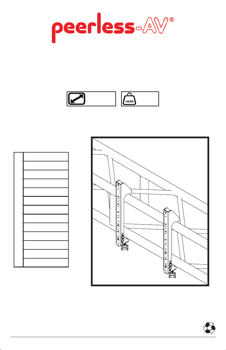
DSF290
TRUSS MOUNT
FOR 12” TRUSS WITH 2” OUTER
DIAMETER TUBING
SF640
SF650
SF660
ST640
ST650
ST660
SP850
FPS-1000
PS -1
PS-2
Mount Compatability for DSF290
DS-VW765-LAND
HPF650
DSVW655
40" - 90"
(102-229 cm)
MAX
175 lb
(79 kg)
1
03-13-13 #:125-9414-2 (04-02-13)
Page 2

2
03-13-13 #:125-9414-2 (04-02-13)
Page 3
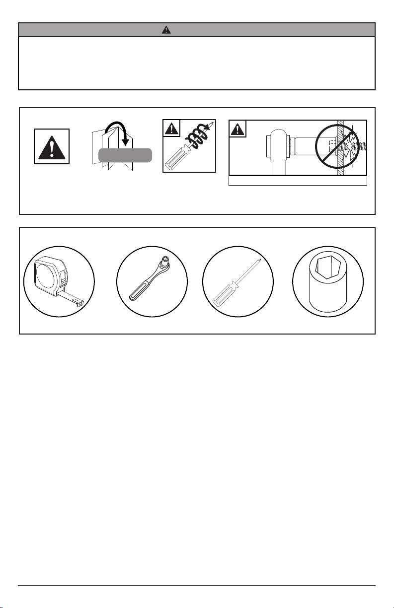
WARNING
ENG - Before installing make sure the supporting truss will support the combined load of the equipment and
hardware. Screws must be tightly secured. Do not overtighten screws or damage can occur and product may fail.
Never exceed the Maximum Load Capacity. Always use an assistant or mechanical lifting equipment to safely lift
and position equipment. This product is intended for indoor use only. Use of this product outdoors could lead to
product failure or personal injury. For support please call customer care at 1-800-865-2112.
Symbols
WARNING
Tools Needed for Assembly.
Skip to step.
#
x3
Screws must get at
least three full turns
and t snug.
Do not over tighten screws
3/8"
(10mm)
3
03-13-13 #:125-9414-2 (04-02-13)
Page 4
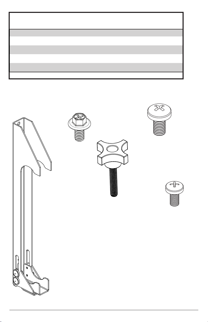
Parts List
Part Description Quantity Part Number
A
hook on adapter bracket 2 202-1532
B
1/4-20 x 1/2" taptite phillips screw 4 520 -1592
C
knob 2 560- 0255
D
M8 x 16mm phillips screw 4 520- 9257
E
M6 x 12mm phillips screw 4 520 -1128
Parts (Before beginning, make sure you have all parts shown below)
A (2)
hook on adapter
bracket
B (4)
taptite phillips
screw
C (2)
knob
D (4)
M8 x 16mm
phillips
screw
E (4)
M6 x 12mm
phillips
screw
4
03-13-13 #:125-9414-2 (04-02-13)
Page 5

vv
a SF640
SF650
SF660
ST640
ST650
ST660
b SP850
FPS-1000
c PS-1
PS-2
Mount Compatability for DSF290
d DS-VW765-LAND
e HPF650
f DSVW655
1
Horizontal Truss Conguration Reference
15.75”
400mm
DSF290 mount DSF290 with accessory mount
11.81”
300mm
7.87”
200mm
3.94”
100mm
7.87”
200mm
d,f
a,c
b,e
e
a,b
c
f
d
3b3a
WARNING
• It is the responsibility of the installer to verify that the truss to which DSF290 is anchored will safely support
four times the combined load of all attached components and equipment
5
03-13-13 #:125-9414-2 (04-02-13)
Page 6

2
C
3a-1
A
x3
Screws must get at
least three full turns
and t snug.
Locate appropriate mounting hole positions for
specic display VESA pattern and secure using
hardware provided as shown.
PORTRAIT ORIENTATION
FOR HORIZONTAL TRUSS
LANDSCAPE ORIENTATION
FOR VERTICAL TRUSS
15.75”
400mm
7.87”
200mm
11.81”
300mm
LANDSCAPE ORIENTATION
FOR HORIZONTAL TRUSS
PORTRAIT ORIENTATION
FOR VERTICAL TRUSS
3.94”
100mm
7.87”
200mm
D or E
D or E
6
03-13-13 #:125-9414-2 (04-02-13)
Page 7

3a-2
Hook the assembly on and secure using the two
knobs to clamp onto the truss.
HORIZONTAL TRUSS
SIDE VIEW
VERTICAL TRUSS
TOP VIEW
7
03-13-13 #:125-9414-2 (04-02-13)
Page 8

3b-1
Install additional accessory mount using
instructions supplied with separate product
models.
3b-2
Loosely fasten the hook on adapter brackets
to the truss so they are secured but can still
be repositioned.
ST650 DEPICTED
SUPPLIED
SEPARATELY
8
03-13-13 #:125-9414-2 (04-02-13)
Page 9

3b-2
Use the outermost compatible hole positions to mount the plate supplied with separate mount and secure using taptite
screws provided.
Tighten knobs rmly to secure assembly to truss
NOTE: ST650 DEPICTED
MOUNTING PLATES MAY VARY SLIGHTLY
VERTICAL TRUSS
B
Use the outermost compatible hole positions to mount the plate supplied with separate mount and secure using taptite
screws provided.
Tighten knobs rmly to secure assembly to truss
HORIZONTAL TRUSS
NOTE: ST650 DEPICTED
MOUNTING PLATES MAY VARY SLIGHTLY
B
3b-3
Complete assembly using instructions provided
with separate mount.
9
03-13-13 #:125-9414-2 (04-02-13)
Page 10

10
03-13-13 #:125-9414-2 (04-02-13)
Page 11

Peerless Industries, Inc. (“Peerless”) warrants to original end-users of Peerless® products will be free from defects in material and
LIMITED FIVE-YEAR WARRANTY
workmanship, under normal use, for a period of ve years from the date of purchase by the original end-user (but in no case longer than
six years after the date of the product's manufacture). At its option, Peerless will repair or replace, or refund the purchase price of, any
product which fails to conform with this warranty.
In no event shall the duration of any implied warranty of merchantability or tness for a particular purpose be longer than the
period of the applicable express warranty set forth above. Some states do not allow limitations on how long a implied warranty lasts,
so the above limitation may not apply to you.
This warranty does not cover damage caused by (a) service or repairs by the customer or a person who is not authorized for such service
or repairs by Peerless, (b) the failure to utilize proper packing when returning the product, (c) incorrect installation or the failure to follow
Peerless' instructions or warnings when installing, using or storing the product, or (d) misuse or accident, in transit or otherwise, including
in cases of third party actions and force majeure.
In no event shall Peerless be liable for incidental or consequential damages or damages arising from the theft of any product,
whether or not secured by a security device which may be included with the Peerless® product. Some states do not allow the
exclusion or limitation of incidental or consequential damages, so the above limitation or exclusion may not apply to you.
This warranty is in lieu of all other warranties, expressed or implied, and is the sole remedy with respect to product defects. No dealer,
distributor, installer or other person is authorized to modify or extend this Limited Warranty or impose any obligation on Peerless in
connection with the safe of any Peerless® product.
This warranty gives specic legal rights, and you may also have other rights which vary from state to state.
11
03-13-13 #:125-9414-2 (04-02-13)
Page 12

Peerless-AV
2300 White Oak Circle
Aurora, IL 60502
Email: tech@peerlessmounts.com
Ph: (800) 865-2112
Fax: (800) 359-6500
www.peerless-av.com
© 2013, Peerless Industries, Inc.
12
03-13-13 #:125-9414-2 (04-02-13)
 Loading...