

Page 1
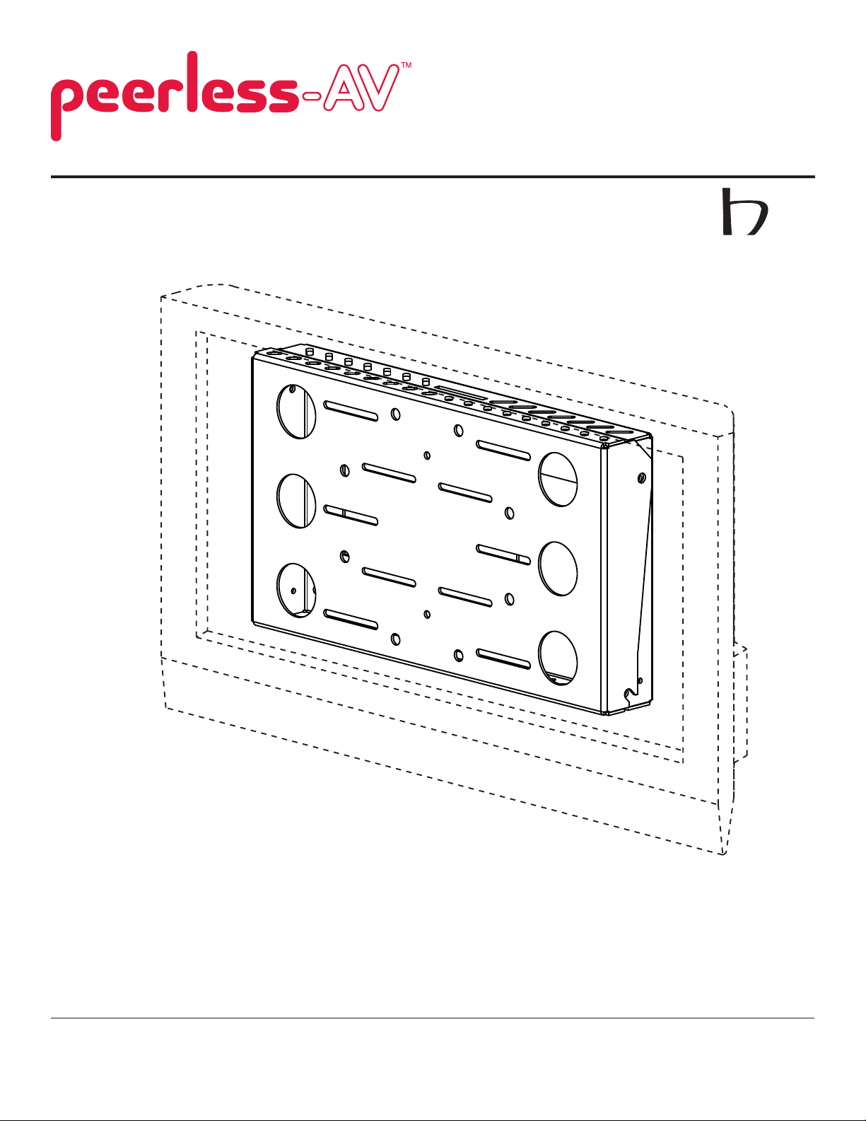
Installation and Assembly
Model: DS509
os
For OSHPD installations,
please contact Peerless
Customer Service for a
copy of the OPA.
pd
Maximum Load Capacity:
200 lb (90.7 kg)
2300 White Oak Circle • Aurora, IL 60502 • (800) 865-2112 • Fax: (800) 359-6500 • www.peerlessmounts.com
ISSUED: 04-06-09 SHEET #:125-9059-3 07-11-11
Page 2

IMPORTANT! Read instruction sheet before you start installation and assembly.
WARNING
• Do not begin to install your Peerless product until you have read and understood the instructions and warnings
contained in this Installation Sheet. If you have any questions regarding any of the instructions or warnings, for US
customers please call Peerless customer care at 1-800-865-2112, for all international customers, please contact
your local distributor.
• This product should only be installed by someone of good mechanical aptitude, has experience with basic building
construction, and fully understands these instructions.
• Make sure that the supporting surface will safely support the combined load of the equipment and all attached
hardware and components.
• Never exceed the Maximum Load Capacity. See page one.
• If mounting to wood wall studs, make sure that mounting screws are anchored into the center of the studs. Use of
an "edge to edge" stud fi nder is highly recommended.
• Always use an assistant or mechanical lifting equipment to safely lift and position equipment.
• Tighten screws fi rmly, but do not overtighten. Overtightening can damage the items, greatly reducing their holding
power.
• This product is intended for indoor use only. Use of this product outdoors could lead to product failure and personal
injury.
• This product was designed to be installed on the following wall construction only;
WALL CONSTRUCTION HARDWARE REQUIRED
• Wood Stud Included
• Wood Beam Included
• Solid Concrete Included
• Cinder Block Included
• Metal Stud Included
• Brick Contact Qualifi ed Professional
• Other or unsure? Contact Qualifi ed Professional
Tools Needed for Assembly
• stud fi nder ("edge to edge" stud fi nder is recommended)
• phillips screwdriver
• drill
• 1/4" (6 mm) bit for concrete and cinder block wall
• 5/32" (4 mm) bit for wood stud wall
• level
• 6 mm allen wrench
Table of Contents
Parts List.................................................................................................................................................................................3
Installation to Double Wood Stud Wall ...................................................................................................................................4
Installation to Solid Concrete or Cinder Block ........................................................................................................................5
Installation to Metal Stud Wall ................................................................................................................................................6
Attaching Tilt Plate to Screen .................................................................................................................................................8
Attaching Tilt Plate to Wall Plate .............................................................................................................................................9
2 of 9
ISSUED: 04-06-09 SHEET #:125-9059-3 07-11-11
Page 3
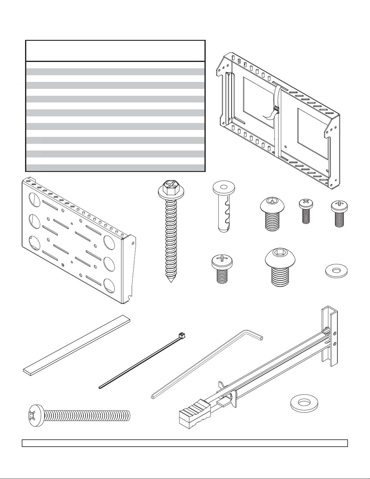
Before you begin, make sure all parts shown are included with your product.
Description Qty. Part #
A
wall plate 1 145-1055
B
tilt plate 1 145-1053
C
#14 x 2.5" wood screw 4 5S1-015-C03
D
concrete anchor 4 590-0097
E
M8 x 15 mm socket pin screw 4 520-1068
F
M4 x 12 mm phillips screw 4 504-9013
G
M5 x 12 mm phillips screw 4 520-1027
H
M6 x 12 mm phillips screw 4 520-1128
I
M10 x 15 mm socket screw 4 520-9262
J
#8 SAE flat washer 4 540-1001
K
3/4" x 3/16" x 10" adhesive strip 2 570-1029
L
cable tie 4 560-9711
M
4 mm allen wrench 1 560-9646
N
1/4 - 20 x 2.5" phillips screw 4 520-9521
O
toggler 4 560-9708
P
1/4" flat washe
r
8 540-9440
Parts List
Parts may appear slightly different than illustrated.
A
C
D
B
E
F
G
J
H
I
K
L
M
O
P
N
3 of 9
ISSUED: 04-06-09 SHEET #:125-9059-3 07-11-11
Page 4

Installation to Double Wood Stud Wall
WARNING
• Installer must verify that the supporting surface will safely support the combined load of the equipment and all
attached hardware and components.
• Tighten wood screws so that wall plate is fi rmly attached, but do not overtighten. Overtightening can damage the
screws, greatly reducing their holding power.
• Never tighten in excess of 80 in. • lb (9 N.M.).
• Make sure that mounting screws are anchored into the center of the stud. The use of an "edge to edge" stud fi nder
is highly recommended.
• Hardware provided is for attachment of mount through standard thickness drywall or plaster into wood studs. Installers are responsible to provide hardware for other types of mounting situations.
Wall plate (A) can be mounted to two studs that are 16" apart. Use a stud fi nder to locate the edges of the studs.
1
Use of an edge-to-edge stud fi nder is highly recommended. Based on their edges, draw a vertical line down
each stud’s center. Place wall plate on wall as a template. Level plate, and mark the center of the four mounting
holes. Make sure that the mounting holes are on the stud centerlines. Drill four 5/32" (4 mm) dia. holes 2-1/2"
(64 mm) deep. Make sure that the wall plate is level, secure it using four #14 x 2.5" wood screws (C) as shown.
Skip to step 2
C
A
STUD
4 of 9
ISSUED: 04-06-09 SHEET #:125-9059-3 07-11-11
Page 5

Installation to Solid Concrete or Cinder Block
WARNING
• When installing Peerless wall mounts on cinder block, verify that you have a minimum of 1-3/8" of actual concrete
thickness in the hole to be used for the concrete anchors. Do not drill into mortar joints! Be sure to mount in a solid
part of the block, generally 1" minimum from the side of the block. Cinder block must meet ASTM C-90 specifi ca-
tions. It is suggested that a standard electric drill on slow setting is used to drill the hole instead of a hammer drill to
avoid breaking out the back of the hole when entering a void or cavity.
• Concrete must be 2000 psi density minimum. Lighter density concrete may not hold concrete anchor.
• Make sure that the supporting surface will safely support the combined load of the equipment and all attached hardware and components.
Make sure that wall plate (A) is level, use it as a
1
template to mark four mounting holes. Drill four 1/4"
(6 mm) dia. holes to a minimum depth of 2.5"
(64 mm). Insert anchors (D) in holes fl ush with wall as
shown in fi gure 1.2. Place wall plate over anchors and
secure with #14 x 2.5" screws (C). Level, then tighten
all fasteners.
Skip to step 2
WARNING
• Tighten screws so that wall plate is fi rmly attached,
but do not overtighten. Overtightening can damage
screws, greatly reducing their holding power.
• Never tighten in excess of 80 in. • lb (9 N.M.).•
Always attach concrete anchors directly to loadbearing concrete.
• Never attach concrete anchors to concrete covered
with plaster, drywall, or other fi nishing material. If
mounting to concrete surfaces covered with a fi nish-
ing surface is unavoidable, the fi nishing surface must
be counterbored as shown below. Be sure concrete
anchors do not pull away from concrete when tightening screws. If plaster/drywall is thicker than 5/8",
custom fasteners must be supplied by installer.
C
fi g. 1.1
D
A
fi g. 1.2
1
solid concrete
cinder block
concrete surface
D
CUTAWAY VIEW
wall
plate
INCORRECT CORRECT
plaster/
dry wall
concrete wall
plate
plaster/
dry wall
concrete
5 of 9
Drill holes and insert anchors (D).
2
Place plate (A) over anchors (D) and secure with screws (C).
A
C
D
3
Tighten all fasteners.
ISSUED: 04-06-09 SHEET #:125-9059-3 07-11-11
Page 6

Installation to Metal Studs
WARNING
• Drywall must be 1/2" or thicker, and metal stud must be 24 gauge or thicker.
• Make sure that the wall will safely support the combined load of the equipment and all attached hardware and
components.
• Make sure that togglers are anchored into the center of the studs. The use of an "edge to edge" stud fi nder is highly
recommended.
Using a stud fi nder, locate and mark the edges of the metal stud used in mounting this product. Use of an edge
1
to edge stud fi nder is highly recommended. Use a level to draw a level, vertical line down the center of the stud.
Level wall plate, and mark the center of the four mounting holes. Make sure that the mounting holes are on the stud
centerlines. Drill four 1/2" holes through drywall and metal studs. NOTE: It may be necessary to drill 5/32"
pilot holes prior to drilling 1/2" holes. Install togglers (O) as shown in fi gure 1.3. Loosely fasten wall plate to wall
using four 1/4-20 x 2-1/2" screws (N) and six 1/4" washers (P) as shown in fi gure 1.4. Level, hold, and then tighten
all screws.
fi g. 1.3
1
O
Pivot end of toggler (O).
drill
1/2"
hole
2
O
Push into hole.
3
O
Rotate toggler (O) clockwise to wedge it
against inside walls of metal stud.
4
fi g. 1.4
O
A
P
N
O
Slide plastic cap forward while pulling back
fi rmly on ring.
5
O
Break off excess.
6 of 9
ISSUED: 04-06-09 SHEET #:125-9059-3 07-11-11
Page 7

Placement of Adhesive Strips
Place adhesive strips (K) on the wall plate (A) in location that will allow the most contact with CPU.
2
Note: Placement of adhesive strips will vary depending on size of CPU as shown in fi gure 2.2
fi g. 2.1
fi g. 2.2
A
Placement of adhesive
strips (K) for smaller CPU's
K
Attach CPU to Wall Plate
NOTE: Safety belt may need to be loosened to attach CPU to wall plate (A).
3
Press CPU against adhesive strips on wall plate and tightly secure safety belt against CPU.
Placement of adhesive
strips (K) for larger CPU's
SAFETY
STRAP
CPU
7 of 9
A
ISSUED: 04-06-09 SHEET #:125-9059-3 07-11-11
Page 8

Attaching Adapter Plate to Screen
Attaching adapter plate to screen with VESA hole
4
pattern:
Choose hole pattern and fasteners shown in detail 2 for
mounting screen with VESA mounting patterns. Hand
thread screws (F, G or H) through washers (J or P) and
adapter plate (B) into screen as shown in fi gure 4.1. Screw
must make at least three full turns into the mounting hole
and fi t snug into place. Securely tighten screws.
WARNING
fi g. 4.1
SCREEN
B
• If screws don't get three complete turns in the
screen inserts or if screws bottom out and bracket
is still not tightly secured, damage may occur to
screen or product may fail.
MOUNTING PATTERNS
VESA® 200 x 100 VESA® 200 x 200VESA® 100 x 100
M4 x 12 mm screws (F) with #8
washers (J) or M5 x 12 mm screws
(G) with 1/4" washers (P)
M4 x 12 mm screws (F) with
washers (J), M5 x 12 mm screws (G)
or M6 x 12 mm screws (H)
with 1/4" washers (P)
F, G
J or P
M5 x 12 mm screws (G) or
M6 x 12 mm screws (H) with
1/4" washers (P)
DETAIL 2
or H
Attaching adapter plate to dedicated adapter plates:
Using the hole pattern shown in detail 3, attach the adapter plate (B) to dedicated adapter plate with four
M10 x 15 mm screws (I) as shown in fi gure 4.2. Tighten screws using 6 mm allen wrench (not included).
fi g. 4.2
DEDICATED
ADAPTER PLATE
MOUNTING PATTERN FOR
DEDICA TED ADAPTER PLATES
B
I
DETAIL 3
8 of 9
ISSUED: 04-06-09 SHEET #:125-9059-3 07-11-11
Page 9

Attaching Adapter Plate to Wall Plate
Thread two M8 x 15 mm screws (E) into bottom holes of wall plate (A) leaving 1/8" space between head of screw
5
and wall plate as shown in fi gure 5.1. Guide hook slots of adapter plate (B) onto screws (E), while supporting
weight of screen, align top holes of wall plate and adapter bracket to the desired tilt angle and secure with two
M8 x 15 mm screws (E). Tighten all screws securely.
fi g. 5.1
10° TILT
5° TILT
NO TILT
fi g. 5.2
A
HOOK
SLOTS
E
B
E
1/8"
BOTH
SIDES
WALL NOT SHOWN FOR CLARITY
E
Accessing CPU
Loosen top two M8 x 15 mm screws (E) 1/4 turn and temporarily remove bottom two M8 x 15 mm screws (E) on
6
adapter plate (A) as shown in fi gure 6.1. Swing screen forward and swing support brackets downward into
adapter plate (B) to brace screen in open position as shown in fi gure 6.2.
fi g. 6.1
LOOSEN 1/4 TURN ON
E
BOTH SIDES
fi g. 6.2
A
WALL STRUCTURE AND SCREEN
NOT SHOWN FOR CLARITY
B
BB
A
E
REMOVE
A
SUPPORT BRACKETS
(BOTH SIDES)
9 of 9
All other brand and product names are trademarks or registered trademarks of their respective owners.
ISSUED: 04-06-09 SHEET #:125-9059-3 07-11-11
© 2011, Peerless Industries, Inc. All rights reserved.
 Loading...