

Page 1
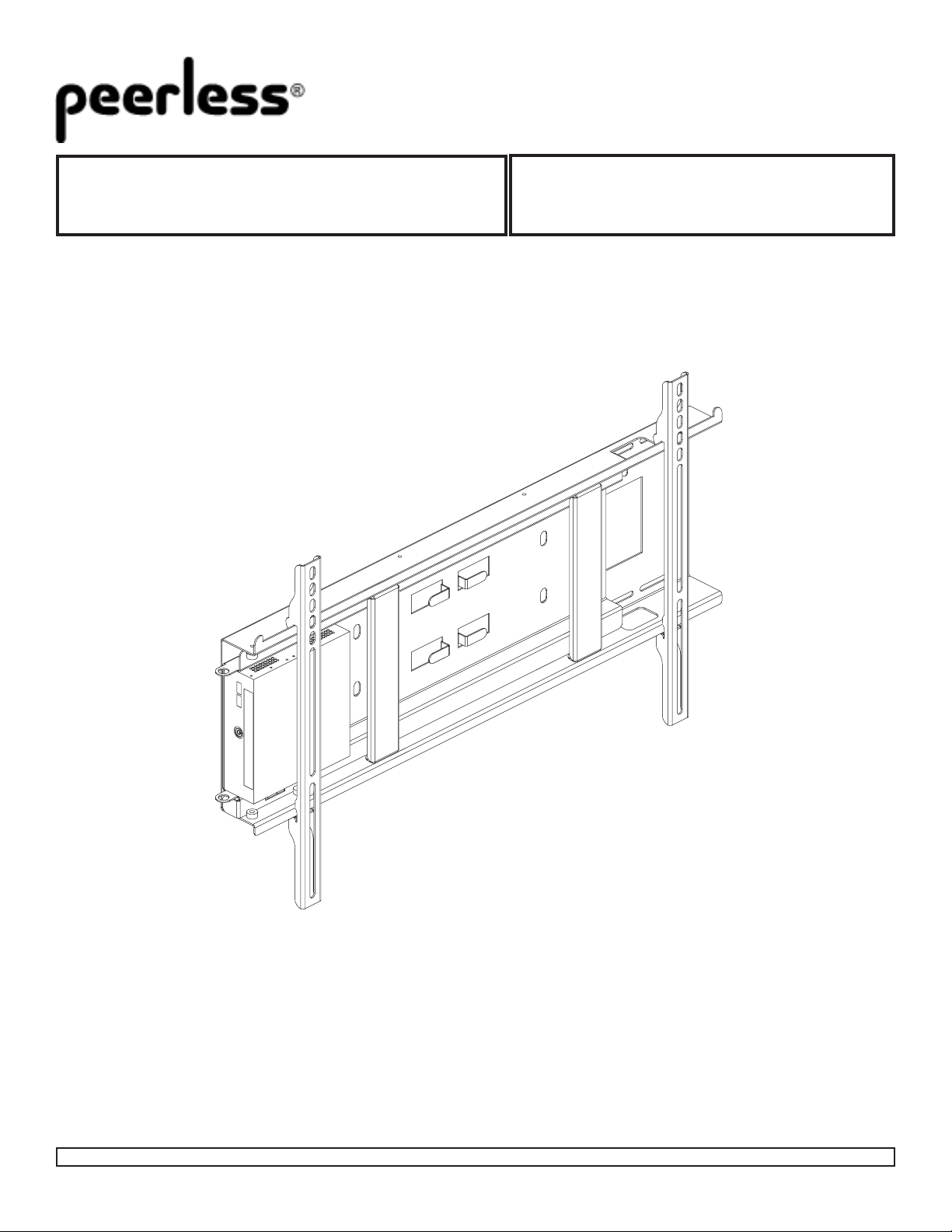
Installation and Assembly:
SLIDE OUT WALL MOUNT
Models: DMU50SM
Visit the Peerless Web Site at www.peerlessmounts.com
Max Load Capacity:125 lb (56.6 kg)
ISSUED: 03-26-09 SHEET #: 125-9060-5 07-26-13
Page 2
Description Qty. Part #
A
wall plate 1
125-1007
B
slide out plate 1
125-1005
C
adapter bracket
2 125-1006
D
M5 x 10 mm socket pin serrated washer head screw 4
510-1126
E
M5 x 16 mm socket pin serrated washer head screw 1
510-1161
F
M5 x 25 mm socket pin serrated washer head screw 2
510-1122
G
4 mm allen wrench
1 560-9646
H
.219 ID x .5 X OD x .5 tall nylon spacer 1
540-1057
I
#14 x 2.5 hex phillips wood screw 4
5S1-015-C03
J
M3 x 8 mm phillips pan screw 4
520-1038
K
#4 flat washer
4 540-1049
L
.219 ID x .5 X OD x .25 tall nylon spacer
4 540-9413
M
3/4 EMT nut 1
560-0049
N
lock and key (not shown)
1 560-0755
O
concrete anchor 4
590-0320
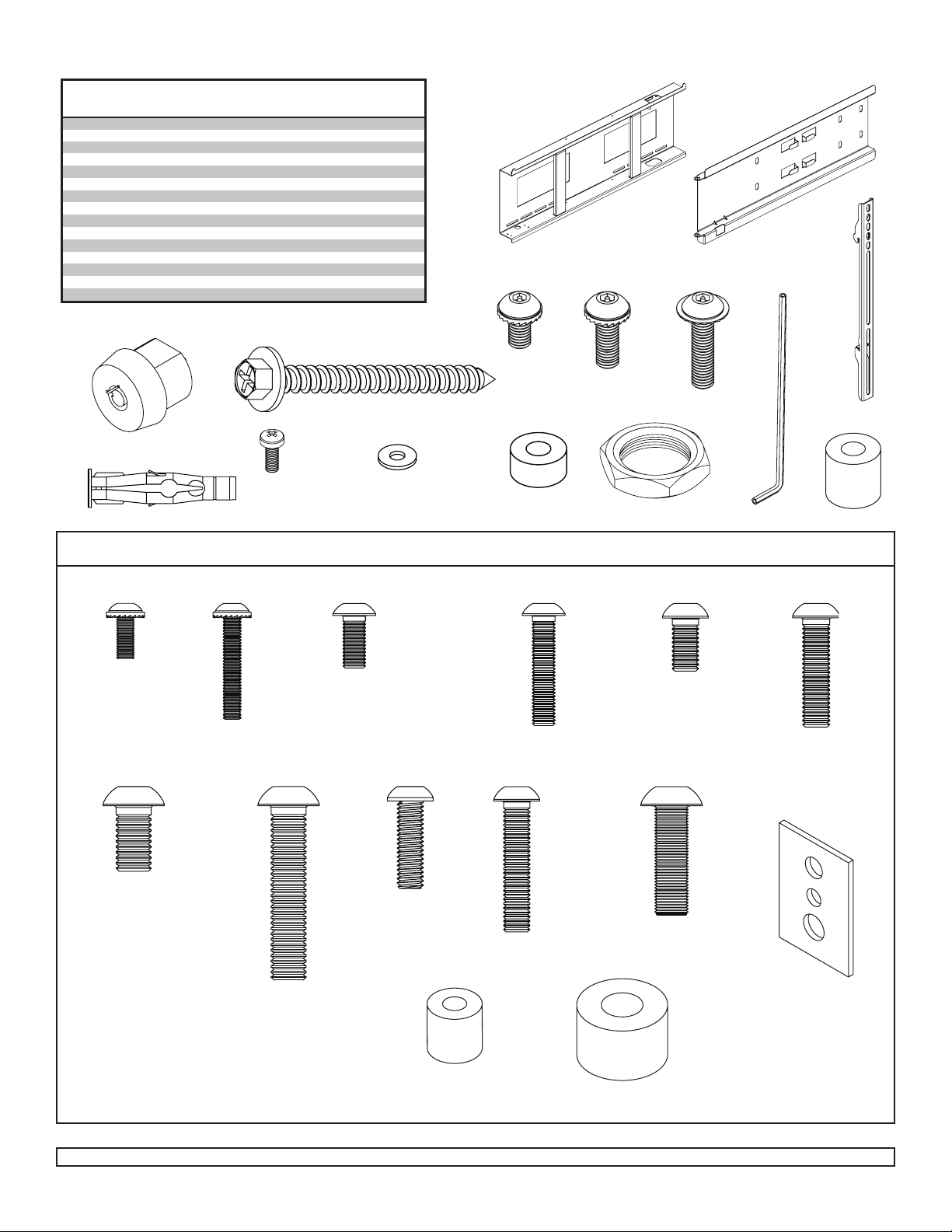
Parts List
IMPORTANT: Read instruction sheet before you start installation and assembly.
Before you start check the parts list to insure all of the parts shown are included.
NOTE: Some parts may appear slightly different than illustrated.
N
I
D
A
E
F
B
C
G
O
J
M
K L
H
Security Adapter Bracket Fasteners
NOTE: The sorted-for-you™ fastener pack included was made specically for your product and may not contain all components.
M4 x 12 mm (6)
(510-1079)
M8 x 15 mm (6)
(520-1068)
M4 x 25 mm (4)
(510-1082)
M8 x 40 mm (4)
(520-1152)
M5 x 12 mm (4)
(520-1064)
M6 x 20 mm (4)
(520-9554)
I.D. .22” (5.6 mm) (4)
M6 x 30 mm (4)
(520-1067)
(540-1057)
M5 x 25 mm (4)
(520-1122)
I.D. .34” (8.6 mm) (4)
M6 x 12 mm (4)
(520-1050)
M6 x 25 mm (4)
(520-1211)
M8 x 25 mm (4)
(520-1101)
multi-washer (6)
(580-1036)
(540-1059)
Visit the Peerless Web Site at www.peerlessmounts.com
ISSUED: 03-26-09 SHEET #: 125-9060-5 07-26-13
Page 3
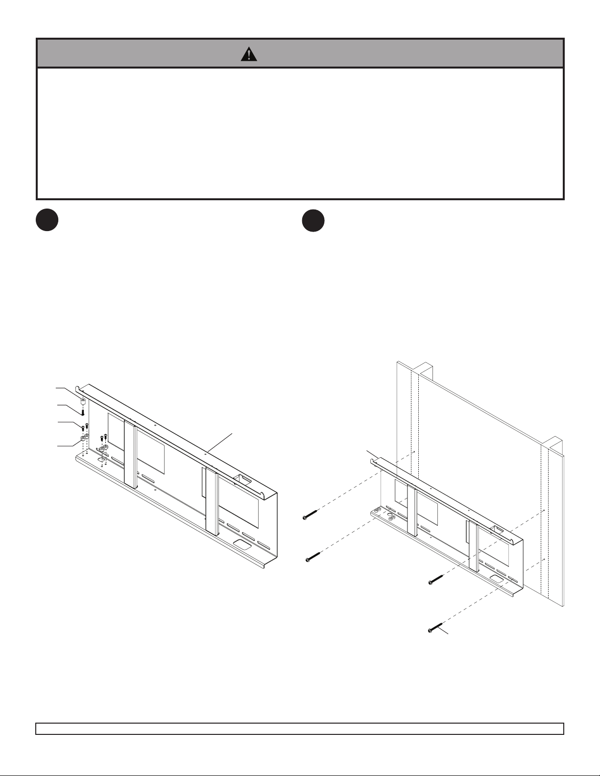
Installation to Wood Stud Walls
WARNING
• Installer must verify that the supporting surface will safely support the combined load of the equipment and all
attached hardware and components.
• Tighten wood screws so that wall plate is rmly attached, but do not overtighten. Overtightening can damage the
screws, greatly reducing their holding power.
• Never tighten in excess of 80 in. • lb (9 N.M.).
• Make sure that mounting screws are anchored into the center of the stud. The use of an “edge to edge” stud nder
is highly recommended.
• Hardware provided is for attachment of mount through standard thickness drywall or plaster into wood studs.
Installers are responsible to provide hardware for other types of mounting situations.
Secure four .219 ID x .5 X OD x .25 tall nylon spacer
1
(L) and four M5 x 10 mm socket pin serrated washer
head screw (D) to bottom of wall plate (A). Secure
one M5 x 16 mm socket pin serrated washer head
screw (E) and one .219 ID x .5 X OD x .5 tall nylon
spacer (H) to top of wall plate as shown below.
H
E
D
A
L
Use a stud nder to locate the edges of the stud.
2
Use of an edge-to-edge stud nder is highly
recommended. Based on its edges, draw a vertical
line down the stud’s center. Place wall plate (A)
on wall as a template. Mark the center of the four
mounting holes. Drill four 5/32” (4 mm) dia. holes
2-1/2” (65 mm) deep. Secure wall plate (A) to wood
stud using four #14 x 2-1/2” wood screws (I) as
shown.
Skip to step 3 on page 5
A
Visit the Peerless Web Site at www.peerlessmounts.com
I
ISSUED: 03-26-09 SHEET #: 125-9060-5 07-26-13
Page 4

Installation to Solid Concrete or Cinder Block
WARNING
• When installing Peerless wall mounts on cinder block, verify that you have a minimum of 1-3/8” of actual concrete
thickness in the hole to be used for the concrete anchors. Do not drill into mortar joints! Be sure to mount in a solid
part of the block, generally 1” minimum from the side of the block. Cinder block must meet ASTM C-90 specications. It is suggested that a standard electric drill on slow setting is used to drill the hole instead of a hammer drill to
avoid breaking out the back of the hole when entering a void or cavity.
• Concrete must be 2000 psi density minimum. Lighter density concrete may not hold concrete anchor.
• Make sure that the supporting surface will safely support the combined load of the equipment and all attached hardware and components.
Make sure that wall plate (A) is level, use it as a
2
template to mark four mounting holes. Drill four
1/4” (6 mm) dia. holes to a minimum depth of
2.5” (64 mm). Insert anchors (O) in holes ush with
wall as shown (right). Place wall plate over anchors
and secure with #14 x 2.5” screws (I). Level, then
tighten all fasteners.
1
concrete
surface
O
WARNING
• Tighten screws so that wall plate is rmly attached,
but do not overtighten. Overtightening can damage
screws, greatly reducing their holding power.
• Never tighten in excess of 80 in. • lb (9 N.M.).
WARNING
• Always attach concrete anchors directly to loadbearing concrete.
• Never attach concrete anchors to concrete covered
with plaster, drywall, or other nishing material. If
mounting to concrete surfaces covered with a nishing surface is unavoidable, the nishing surface must
be counterbored as shown below. Be sure concrete
anchors do not pull away from concrete when tightening screws. If plaster/drywall is thicker than 5/8”,
custom fasteners must be supplied by installer.
INCORRECT
concrete
A
A
CORRECT
concrete
Drill holes and insert anchors (I).
2
A
I
Place plate (A) over anchors (I) and secure with screws (F).
3
Tighten all fasteners.
solid concrete
O
I
O
cinder block
plaster/
dry wall
plaster/
dry wall
CUTAWAY VIEW
Visit the Peerless Web Site at www.peerlessmounts.com
A
ISSUED: 03-26-09 SHEET #: 125-9060-5 07-26-13
Page 5

Lock Installation
Secure lock (N) into wall plate (A) by using parts (provided with lock) and 3/4” EMT nut (M) as shown.
3
Note: Lock will NOT function properly if lock parts are in wrong position.
A
M
N
N
A
Visit the Peerless Web Site at www.peerlessmounts.com
ISSUED: 03-26-09 SHEET #: 125-9060-5 07-26-13
Page 6

Installing Adapter Brackets
WARNING
• Tighten screws so adapter brackets are rmly attached. Do not tighten with excessive force. Overtightening can
cause stress damage to screws, greatly reducing their holding power and possibly causing screw heads to become
detached. Tighten to 40 in. • lb (4.5 N.M.) maximum torque.
• If screws don’t get three complete turns in the screen inserts or if screws bottom out and bracket is still not tightly
secured, damage may occur to screen or product may fail.
To prevent scratching the screen, set a cloth on a at, level surface that will support the weight of the screen. Place
4
screen face side down. If screen has knobs on the back, remove them to allow the adapter brackets to be attached.
Place adapter brackets (C) on back of screen, align to holes, and center on back of screen as shown below. Attach
the adapter brackets to the back of the screen using the appropriate combination of screws, multi-washers, and
spacers as shown in gure 4.1 or 4.2.
NOTE: Top and bottom holes on screen must always be used.
Verify that all holes are properly aligned, and then tighten screws using a phillips screwdriver.
X
MULTI-WASHER
CENTER BRACKETS
C
MEDIUM HOLE FOR M5 SCREWS
SMALL HOLE FOR M4 SCREWS
LARGE HOLE FOR M6 SCREWS
VERTICALLY ON BACK
OF SCREEN
NOTE: “X” dimensions should be equal.
X
Notes:
• The number of fasteners used will vary,
depending upon the type of screen.
• Multi-washers and spacers may not be
used, depending upon the type of screen.
• Use the corresponding hole in the multi-
washer that matches your screw size.
NOTE: For at back screens proceed to step 4-1. For bump-out or recessed back screen skip to step 4-2.
Visit the Peerless Web Site at www.peerlessmounts.com
ISSUED: 03-26-09 SHEET #: 125-9060-5 07-26-13
Page 7

For Flat Back Screen
Refer to Screen Compatibility Chart to determine the proper fastener to use. Visit www.peerlessmounts.com/2
4-1
for a full screen compatibility chart for this mount.
Begin with the shortest length screw, hand thread through multi-washer and adapter bracket (C) into screen as
shown below. Screw must make at least three full turns into the mounting hole and t snug into place. Do not over
tighten. If screw cannot make three full turns into the screen, select a longer length screw from the bafed fastener
pack. Repeat for remaining mounting holes, level brackets and tighten screws.
NOTE: Spacers may not be used, depending upon the type of screen.
g 4.1
SCREEN
MULTI-WASHER
SCREW
ADAPTER BRACKET (C)
If you have any questions, please call Peerless customer care at 1-800-865-2112.
For Bump-out or Recessed Back Screen
Refer to Screen Compatibility Chart to determine the proper fastener to use. Visit www.peerlessmounts.com/2
4-2
for a full screen compatibility chart for this mount.
Begin with longer length screw, hand thread through multi-washer, adapter bracket (C) and spacer in that order
into screen as shown below. Screw must make at least three full turns into the mounting hole and t snug into
place. Do not over tighten. If screw cannot make three full turns into the screen, select a longer length screw from
the bafed fastener pack. Repeat for remaining mounting holes, level brackets and tighten screws.
SCREEN
SCREEN
SPACER
g 4.2
MULTI-WASHER
SCREW
If you have any questions, please call Peerless customer care at 1-800-865-2112.
Visit the Peerless Web Site at www.peerlessmounts.com
ADAPTER BRACKET (C)
ISSUED: 03-26-09 SHEET #: 125-9060-5 07-26-13
Page 8

Mounting and Removing Flat Panel Screen
WARNING
• Always use an assistant or mechanical lifting equipment to safely lift and position the at panel screen.
Hook adapter brackets (C) onto wall plate (A) as
5
shown in g. 5.1. Then slowly swing screen in as
shown. Tighten M5 x 25 mm socket pin serrated
washer head screws (F), using security allen
wrench (G), clockwise at least six times to prevent
screen from being removed as shown in g. 5.1.
Screen can be adjusted horizontally if desired.
NOTE: To lock the screen down, fully tighten M5 x
25 mm socket pin serrated washer head screws (F)
to wall plate as shown in cross section.
To remove screen from mount, loosen M5 x 25 mm
socket pin serrated washer head screws (F) and
swing screen away from mount, and lift screen off of
mount.
• Do not tighten screws with excessive force.
Overtightening can cause damage to mount. Tighten
screws to 40 in. • lb (4.5 N.M.) maximum torque.
CAUTION
C
A
F
g 5.1
g 5.2
Visit the Peerless Web Site at www.peerlessmounts.com
ISSUED: 03-26-09 SHEET #: 125-9060-5 07-26-13
Page 9

Secure media box to slide out bracket (B) using four #4 at washers (K) and four M3 x 8 mm phillips pan screws
6
(J) as shown in g. 6.1. Position the slide out plate (B) into wall plate (A) making sure that the edge of the slide
out plate (B) is inside spacers. Slide plate in until it is stopped by ange in top as shown in g. 6.2. Use nger
holes when sliding slide out bracket (B) in and out of wall plate (A).
Note: once slide out bracket (B) is in place use key (located with lock) to lock. Be sure to keep key in a safe place,
as you will not be able to remove the media box without it.
J
K
FINGER
HOLES
B
Detail 1
MEDIA
BOX
B
FLANGE
g. 6.2
g. 6.1
A
SPACERS
Visit the Peerless Web Site at www.peerlessmounts.com
ISSUED: 03-26-09 SHEET #: 125-9060-5 07-26-13
© 2013 Peerless Industries, Inc. All rights reserved.
All other brand and product names are trademarks or registered trademarks of their respective owners.
Peerless is a registered trademark of Peerless Industries, Inc.
 Loading...