

PEERLESS SERIES DE, DE-03, DE-04, DE-05, DE-06 Installation, Operation & Maintenance Manual
Page 1

DE
Boilers
Installation,
Operation Et
Maintenance
Manual
PEERLESS _
CAST IRON BOILERS
Page 2

4 Sizes 3-6 Sections 70.0 to 165.0 MBH CSA Input
bAFUE ¸¸¸
Natural or LP Gas
Fan Assisted for "Through the Wall" Venting or
Chimney Venting
• Can be Vented into a Lined Masonnj Chimney
• Ideal Where the Chimney is Inadequate or Unavailable
• Uses 3"diameterAL29 4C SS Vent Pipe for 'Through the Wall" or
"Vertical" Venting Applications
Steel Push Nipples
• Provide a Permanent Water Tight Seal Betw_Jen Sections
• Una[['ected by Petroleum and Other Contaminants
Deluxe Insulated Enameled Steel Jacket
• Reduces Boiler Ileal Loss
• Completely Encloses Gas Valve and Bartlel_
Safety Controls
• Flame Roll Out Shirt QffSwitch
• Difj-_.rential Pressure Switch
_)SinarlVt_h_(_ ks a r('gisl(_red Irademark qf Honeywell Corporatioa
• Honeywell Operating Controls
• Honeywell SmartValve ® Intermittent Ignition
• Taco 007 Circulator
• 30 PSI Safety Relief Valve
• Non-Combustible Floor Pan
• Grundfos Circulator
• AL29-4C Stainless Steel Venting Components
• 50 PSI Safety Relief Valve
Ik'cHt'._s l letllt'r Compatiy is pleased to ql]t't otte q[ lhe most compr_zhensive warranty prograrru,; ill
rht; ilKltlslr'tj. All ['_,_'He._s rt!sidential cas! iron !)oil_'rs inchld¢" a.]ull one !lear tvan_lnly. A limited,
l!]_!litllt, u!ol_Yully is plovi(lt!d.lbr the' ('a,sl it,)It s_,cliotls (!1 Pe_'rlits_; r('sidteiIlinl hal lvalel boilers.
l'_'_'tl('xs (lisa plol_idt's (1 lir_lilt'd, Ii'lt _]t'of ti_o¢'¢'_Ittl{l oll lilt, (;(lat iroll .'_('cliorls q[ ils r_'sidt_tltkd _;leolll
!K)Jl(ff%, ["iD(" (ll](I {I'll {]e(JY (_xlelt(]e(J III(IITCIIIIi('S 011 11(11"I5 (ll](t [(l]?dJr ofe l[olll (l{l(liIcl_)l_?. [_ltJ(isu COFISILli
Pt_t'II_'N_; lI_'(Ih'l (_t)lltl)flll!l tol Complt'ft" Itl_lll_llllt] it!J()trtl(ltiO¢l.
PGGRLESS ®
CAST IRON BOILERS
Peerless Heater Company - 231 North Walnut Street * Boyertown. PA 19512-1021 * 610-367-2153 • www.peerless-heater.com
FAB DE 1tO 15102 5M}
Prlrlted irl U S A
Page 3

TABLE OF CONTEN S
USING THIS MANUAL 1
A. INSTALLATION SEQUENCE ............. 1
B. SPECIAL ATTENTION BOXES ........... 1
1. PREINSTALLATION 2
A. ACCESSIBILITY CLEARANCES .......... 2
B. CLEARANCE FROM COMBUSTIBLE
CONSTRUCTION ..................... 2
C. AFR FOR COMBUSTION AND
VENTILATION ....................... 2
D. LIQUEFIED PETROLEUM (LP) GAS ....... 4
E. INSTALLATION SURVEY ............... 4
E PLANNING THE LAYOUT ............... 4
2. BOILER SET.;UP 5
3.
A. BOILER SUPPLY AND RETURN .......... 6
B. SAFETY RELIEF VALVE ................ 7
C. PIPING FOR ZONED SYSTEMS .......... 8
D. EXPANSION TANK .................... 9
E. INDIRECT-FIRED WATER HEATER ........ 9
E FREEZE PROTECTION ................. 9
4. VENTING _ 10
A. GENERAL .......................... 10
B, CHIMNEY VENTING .................. 10
C. DIRECT EXHAUST
HORIZONTAL VENTING- . ............. 11
D. DIRECT EXHAUST
VERTICAL VENTING .................. 13
E. BOILER REMOVAL FROM
COMMON VENTING SYSTEM .......... 14
5. GASPIPING: ; __ " ....... ........
6. ELECTRICAL 17
A. WIRING ........................... 17
B. ZONED SYSTEM WIRING ............. 17
C. CONTROLS ........................ 17
D. SEQUENCE OF OPERATION ........... 18
7, START-UP PR_CE_URES_ _ _._ 2,1
A. COMPLETING THE INSTALLATION ...... 21
B. CONTROL DESCRIPTIONS ............. 24
C. ADJUSTMENT OF GAS PRESSURE
REGULATOR ....................... 24
D. CHECKING BURNER INPUT ............ 24
E. CHECK-OUT PROCEDURE ............. 25
A. SHUT-DOWN CAUSED BY PILOT OUTAGE,
PRESSURE SWITCH OR FLAME ROLL-OUT
SAFETY SHUT-OFF SWITCH ........... 26
B. TROUBLESHOOTING GUIDES .......... 26
C. MEASURING SUCTION PRESSURE ...... 26
A. GENERAL .......................... 30
B. DAILY (WITH BOILER IN USE) .......... 30
C. WEEKLY (WITH BOILER IN USE) ........ 30
D. MONTHLY (WITH BOILER IN USE) ....... 30
E. ANNUALLY (BEFORE START OF HEATING
SEASON) .......................... 31
A. BLOCK!BASE/FLOOR PAN
JACKET/FLUE COLLECTOR ............ 33
B, BASE/BURNERS/MANIFOLD ........... 34
Page 4
r:NilIh_[*.'.lq_*lIqW_,_Ii (*) _,'1l:.J :[olWJ:1h,'_[e.]
Follow the installation instructions provided in this
manuaI in the order shown. The order of these
instructions has been set in order to provide the installer
with a logical sequence of steps that will minimize
potential interferences and maximize safety during
boiler installation.
Throughout this manual you will see special attention
boxes intended to supplement the instructions and make
special notice of potential hazards. These categories
mean, in the judgment of Peerless Heater Company:
Indicates a condition or hazard which will cause
severe personal injury, death or major property
damage.
Indicates a condition or hazard which may cause
severe personal injury, death or major property
damage.
Indicates a condition or hazard which will or can
cause minor personal injury or property damage.
Indicates special attention is needed, but not directly
related to potential personal injury or property
damage.
Page 5
Read carefully, study these instructions before beginning work.
This boiler must be installed by a qualified contractor.
The boiler warranty can be voided if the boiler is not installed, maintained and serviced correctly.
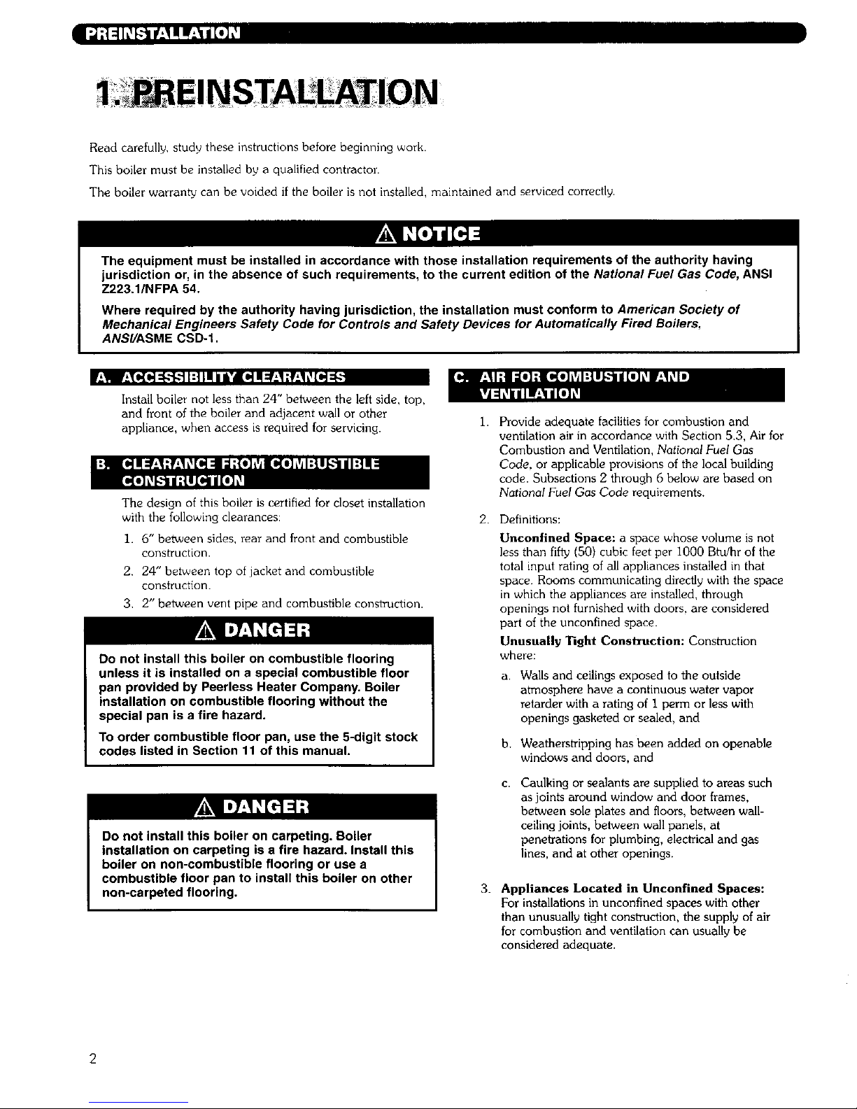
The equipment must be installed in accordance with those installation requirements of the authority having
jurisdiction or, in the absence of such requirements, to the current edition of the National Fuel Gas Code, ANSI
Z223.1/NFPA 54.
Where required by the authority having jurisdiction, the installation must conform to American Society of
Mechanical Engineers Safety Code for Controls and Safety Devices for Automatically Fired Boilers,
ANS//ASME CSD-I.
f__!l l._ll(el:l.'l,.ll:!l! /li'/ [_ I:€_,I:__,1L_[_:(.,.
Install boiler not less than 24" between the left side. top,
and front of the boiler and adjacent wall or other
appliance, when access is required for servicing.
The design of this boiler is certified for closet installation
with the following clearances:
1. 6" between sides, rear and front and combustible
construction.
2. 24" between top of jacket and combustible
construction.
3, 2" between vent pipe and combustible construction.
Do not install this boiler on combustible flooring
unless it is installed on a special combustible floor
pan provided by Peerless Heater Company. Boiler
installation on combustible flooring without the
special pan is a fire hazard.
To order combustible floor pan, use the 5-digit stock
codes listed in Section 11 of this manual.
Do not install this boiler on carpeting. Boiler
installation on carpeting is a fire hazard. Install this
boiler on non-combustible flooring or use a
combustible floor pan to install this boiler on other
non-carpeted flooring.
1.
Provide adequate facilities for combustion and
ventilation air in accordance with Section 5.3, Air for
Combustion and Ventilation, National Fuel Gas
Code, or applicable provisions of the local building
code. Subsections 2 through 6 below are based on
National Fuel Gas Code requirements.
2. Definitions:
Unconfined Space: a space whose volume is not
less than fifty (50) cubic feet per 1000 Btulhr of the
total input rating of all appliances installed in that
space. Rooms communicating directly with the space
in which the appliances are installed, through
openings not furnished with doors, are considered
part of the unconfined space.
Unusually Tight Construction: Construction
where:
a. Walls and ceilings exposed to the outside
atmosphere have a continuous water vapor
retarder with a rating of I perm or less with
openings gasketed or sealed, and
b. Weatherstripping has been added on openable
windows and doors, and
C. Caulking or sealants are supplied to areas such
as joints around window and door frames,
between sole plates and floors, between wall-
ceiling joints, between wall panels, at
penetrations for plumbing, electrical and gas
lines, and at other openings.
3. Appliances Located in Unconfined Spaces:
For installations in unconfined spaceswith other
than unusually tight construction, the supply of air
for combustion and ventilation can usually be
considered adequate.
2
Page 6
4 Unusually Tight Construction:
For equipment located in buildings of unusually tight
construction as defined on the previous page,
provide air for combustion and ventilation using the
methods described in 5a or 5b below.
5. Appliances Located in Confined Spaces:
a. All air from inside the building: Provide two
permanent openings communicating directly with
an additional room or rooms of sufficient volume
so that the combined volume of all spaces meets
the criteria for an unconfined space. Use the total
input of all gas utilization equipment installed in
the combined space in making this
determination.
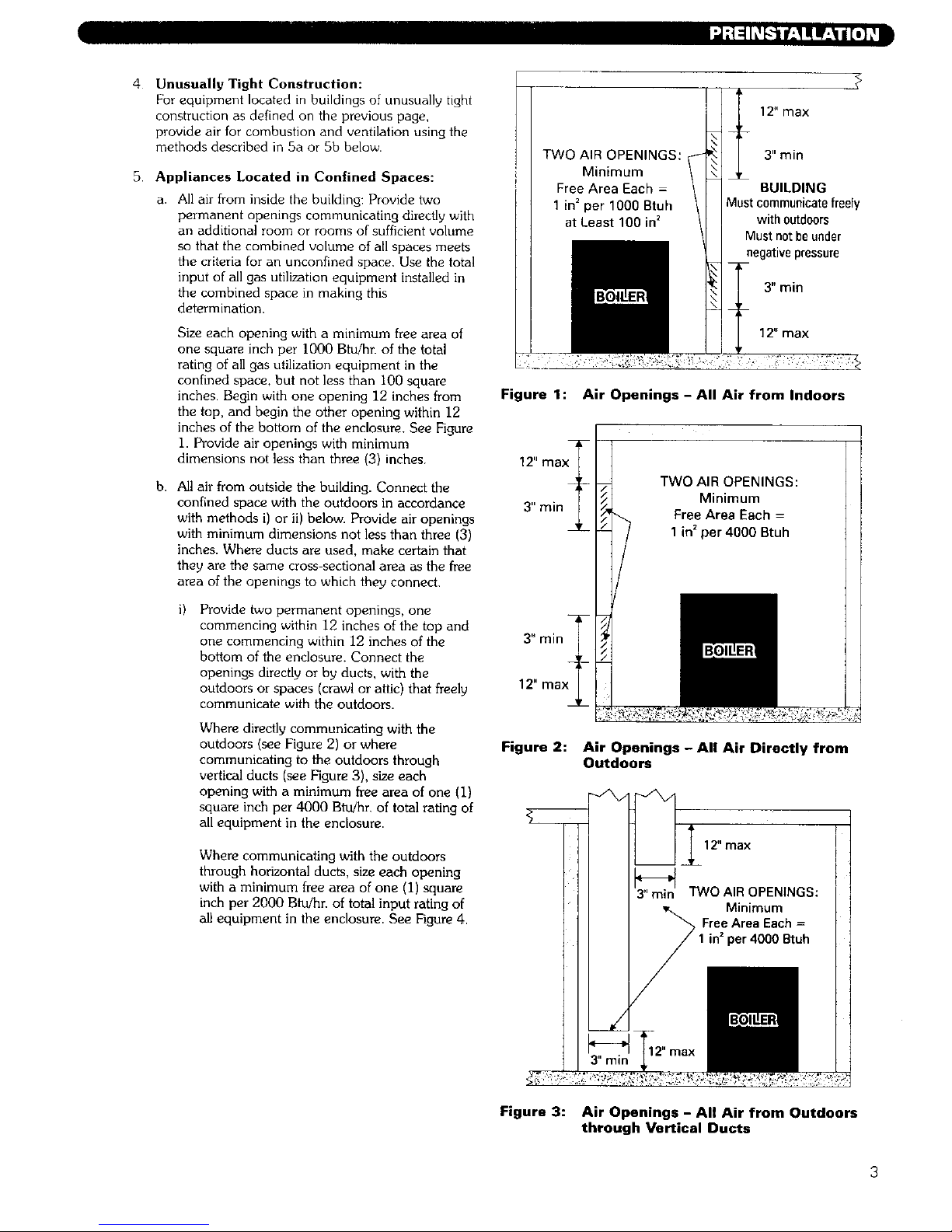
Size each opening with a minimum free area of
one square inch per I000 Btu/hr. of the total
rating of all gas utilization equipment in the
confined space, but not less than I00 square
inches. Begin with one opening 12 inches from
the top, and begin the other opening within 12
inches of the bottom of the enclosure. See Figure
I. Provide air openings with minimum
dimensions not less than three (3) inches.
b. All air from oulside the building. Connect the
confined space with the outdoors in accordance
with methods i) or it) below. Provide air openings
with minimum dimensions not less than three (3)
inches. Where ducts are used, make certain that
they are the same cross-sectional area as the free
area of the openings to which they connect.
Provide two permanent openings, one
commencing within 12 inches of the top and
one commencing within 12 inches of the
bottom of the enclosure. Connect the
openings directly or by ducts, with the
outdoors or spaces (crawl or attic) that freely
communicate with the outdoors.
Where directly communicating with the
outdoors (see Figure 2) or where
communicating to the outdoors through
vertical ducts (see Figure 3), size each
opening with a minimum free area of one (I)
square inch per 4000 Btu!hr, of total rating of
all equipment in the enclosure.
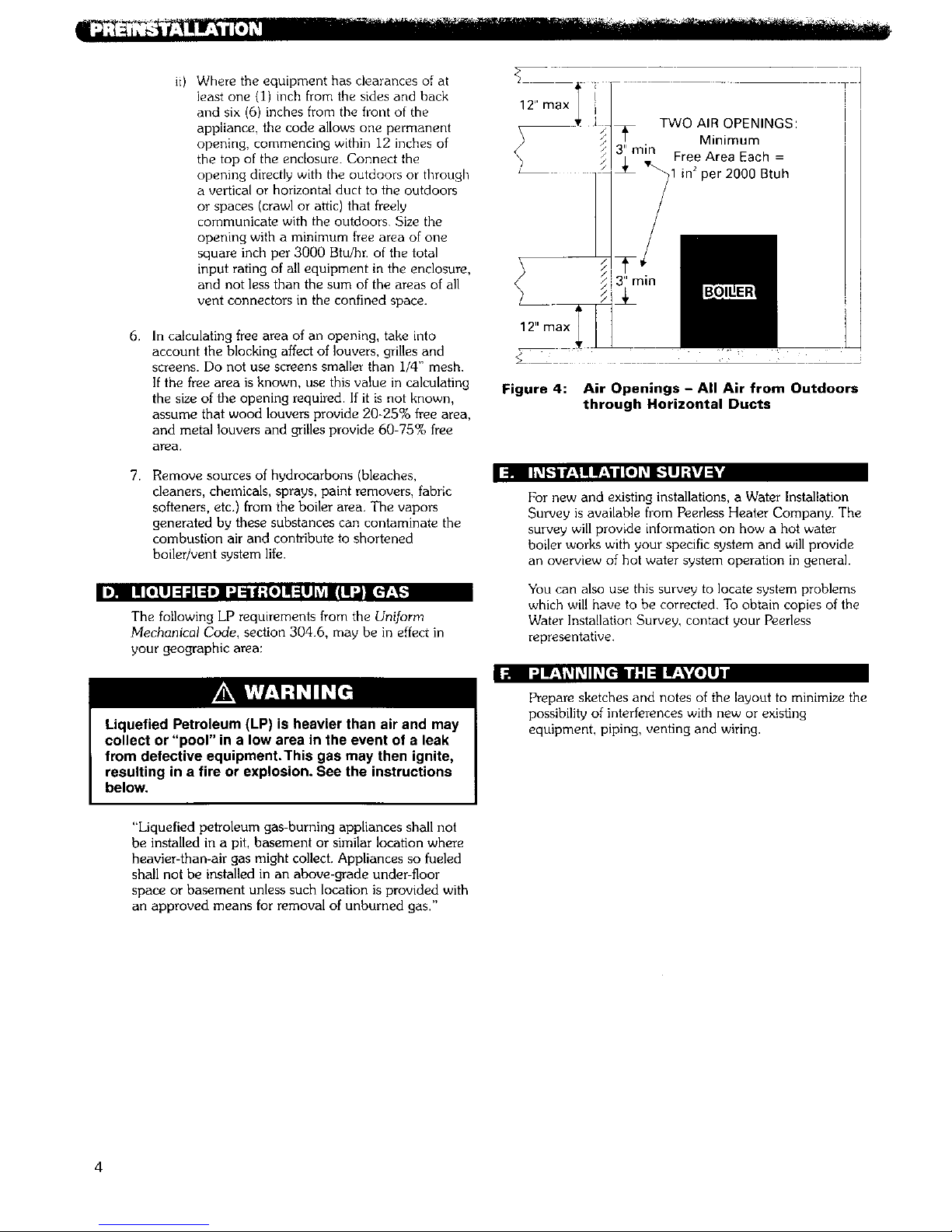
Where communicating with the outdoors
through horizontal ducts, size each opening
with a minimum free area of one (i) square
inch per 2000 Blu/hn of total input rating of
all equipment in the enclosure. See Figure 4.
TWO AIR OPENINGS: _-
Minimum \
Free Area Each = \
1 in2per 1000 Btuh \
at Least 100 in2
t 12" max
3" rain
\
BUILDING
Mastcommunicatefreely
withoutdoors
Must notbeunder
negativepressure
_- 3" rain
12" max
Figure 1: Air Openings - All Air from Indoors
TWO AIR OPENINGS:
Minimum
Free Area Each =
1 in2per 4000 Btuh
Figure 2: Air Openings - All Air Directly from
Outdoors
12" max
Minimum
in _ per 4000 Btuh
Figure 3: Air Openings - All Air from Outdoors
through Vertical Ducts
Page 7
Where the equipment has clearances of at
least one {1) inch from the sides and back
and six (6) inches from the front of the
appliance, the code allows one permanent
opening, commencing within 12 inches of
the top of the enclosure. Connect the
opening directly with the outdoors or through
a vertical or horizontal duct to the outdoors
or spaces (crawl or attic) that freely
communicate with the outdoors Size the
opening with a minimum free area of one
square inch per 3000 Btu/hr. of the total
input rating of all equipment in the enclosure,
and not less than the sum of the areas of all
vent connectors in the confined space.
6,
In calculating free area of an opening, take into
account the blocking affect of louvers, grilles and
screens. Do not use screens smaller than i/4" mesh.
If the free area is known, use this value in calculating
the size of the opening required. If it is not known,
assume that wood louvers provide 20-25% free area,
and metal louvers and grilles provide 60 75% free
area,
I:_ll Ih'_k:-IIw:!I Iz'l / tel [_L"ll I ;kvl:l '
7,
Remove sources of hydrocarbons (bleaches,
cleaners, chemicals, sprays, paint removers, fabric
softeners, etc.) from the boiler area. The vapors
generated by these substances can contaminate the
combustion air and contribute to shortened
boiler/vent system life.
I D_ ! [*Ill :i ;i1:1w] :J:ii| ;{*] Ill:llJ_V_HI _._l[_-'_
The following LP requirements from the Uniform
Mechanical Code, section 304.6, may be in effect in
your geographic area:
12" max
TWO AIR OPENINGS:
Minimum
Free Area Each =
in2per 2000 Btuh
Figure 4: Air Openings - All Air from Outdoors
through Horizontal Ducts
For new and existing installations, a Water Installation
Survey is available from Peerless Heater Company. The
survey will provide information on how a hot water
boiler works with your specific system and will provide
an overview of hot water system operation in general.
You can also use this survey to locate system problems
which will have to be corrected. To obtain copies of the
Water Installation Survey, contact your Peerless
representative.
I:1 I "JI_'l L_h_l h_[rill i" 1:11If'-Vl*lll
Liquefied Petroleum (LP) is heavier than air and may
collect or "pool" in a low area in the event of a leak
from defective equipment.This gas may then ignite,
resulting in a fire or explosion. See the instructions
below.
Prepare sketches and notes of the layout to minimize the
possibility of interferences with new or existing
equipment, piping, venting and wiring.
"Liquefied petroleum gas-burning appliances shall not
be installed in a pit, basement or similar location where
heavier-than-air gas might collect. Appliances so fueled
shall not be installed in an above-grade under-floor
space or basement unless such location is provided with
an approved means for removal of unburned gas."
4
Page 8

1 Provide a sound, leveI foundation Locate boiler as
near to the chimney or outside wall as possible and
centralized with respect to the heating system
2. Locate boiler in front of installation position before
removing crate.
3. If using combustible floor pan, position pan on
foundation or flooring.
4. Separate the wood shipping pallet from the boiler
base by removing two (2) hold-down bolts at each
end of the boiler base.
5. Move boiler into final position. If using combustible
floor pan, install boiler on pan as outlined in the
instructions included with the pan.
Page 9
3. WATER PIPING AND
L"ll I:[e]ll:l;i [--[IJ'];JIk'dl h_'li_l=] .'|:l/IJ;]_,_
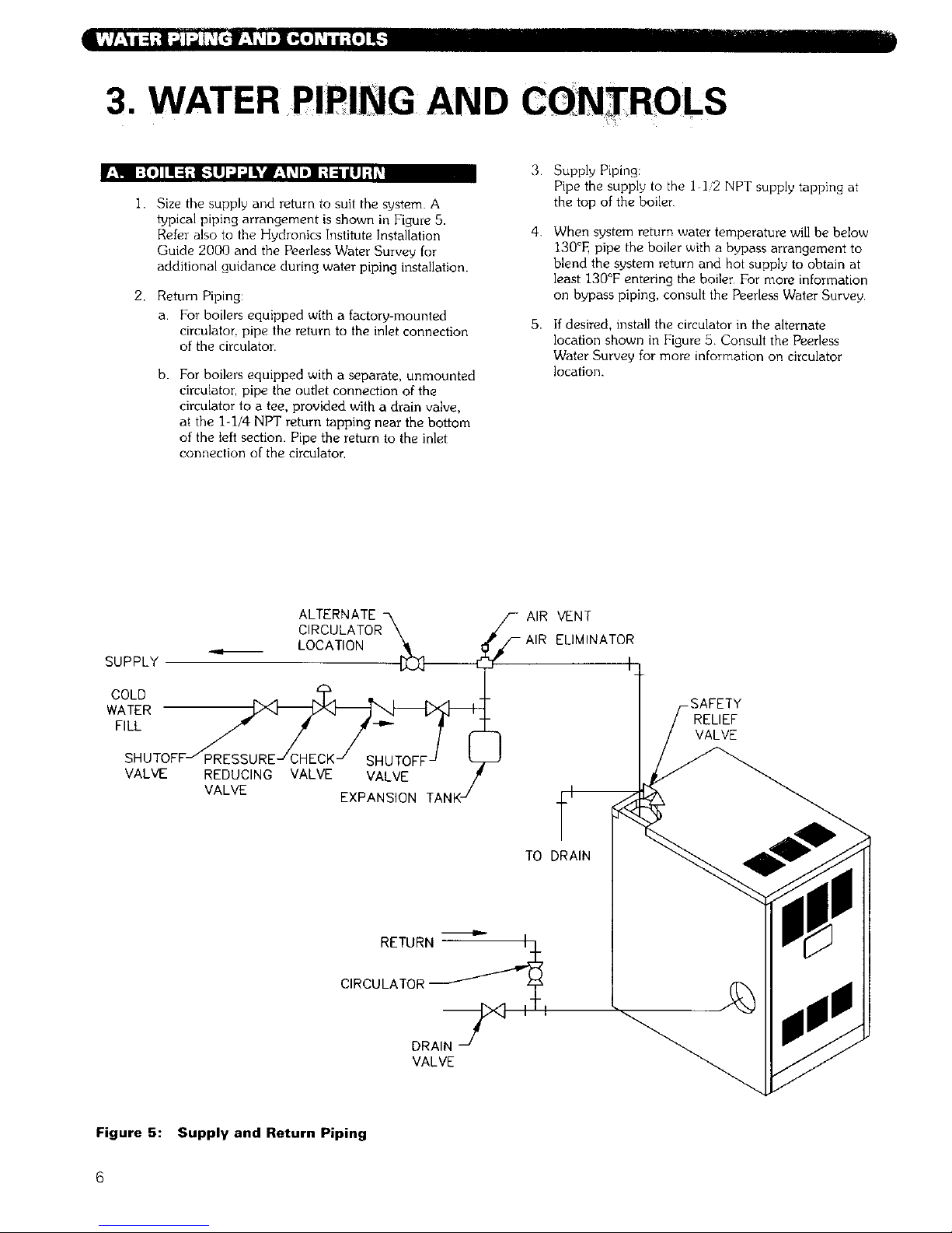
I. Size the supply and return to suit the system. A
typical piping arrangement is shown in Figure 5.
R4er also to the Hydronics Institute Installation
Guide 2000 and the Peerless Water Survey for
additional guidance during water piping installation.
2. Return Piping:
a. For boilers equipped with a factory-mounted
circulator, pipe the return to the inlet connection
of the circulator.
3.
b. For boilers equipped with a separate, unmounted
circulator, pipe the outlet connection of the
circulator to a tee, provided with a drain valve,
at the 1-1/4 NPT return tapping near the bottom
of the left section. Pipe the return to the inlet
connection of the circulator,
4.
5,
Supply Piping:
Pipe the supply to the I ]2 NPT supply tapping at
the top of the boiler
When system return water temperature will be below
130°E pipe the boiler with a bypass arrangement to
blend the system return and hot supply to obtain at
least 130°F entering the boiler For more information
on bypass piping, consult the Peerless Water Survey.
If desired, install the circulator in the alternate
location shown in Figure 5 Consult the Peerless
Water Survey for more information on circulator
location.
SUPPLY
ALTERNATE
CIRCULATOR\
LOCATION
COLD _ .4 N_:_.4 _ , ,.
WATER _
F,LL/- / /-.- ;
SHUTOFFJ PRESSUREJ CHECK J SHUTOFF J
VALVE REDUCING VALVE VALVE
VALVE EXPANSION TANKJ
_- AIR VENT
-AIR ELIMINATOR
RELIEF
VALVE
TO DRAIN
RETURN_/.L_
CIRCULATOR_ y
DRAI:--_ X] III
VALVE
Figure 5: Supply and Return Piping
6
Page 10
6.
7.
8.
9.
install this boiler so that the gas ignition system
components are protected from water (dripping,
spraying, etc.) during appliance operation and
service (circulator replacement, condensate trap,
control replacements, etc.).
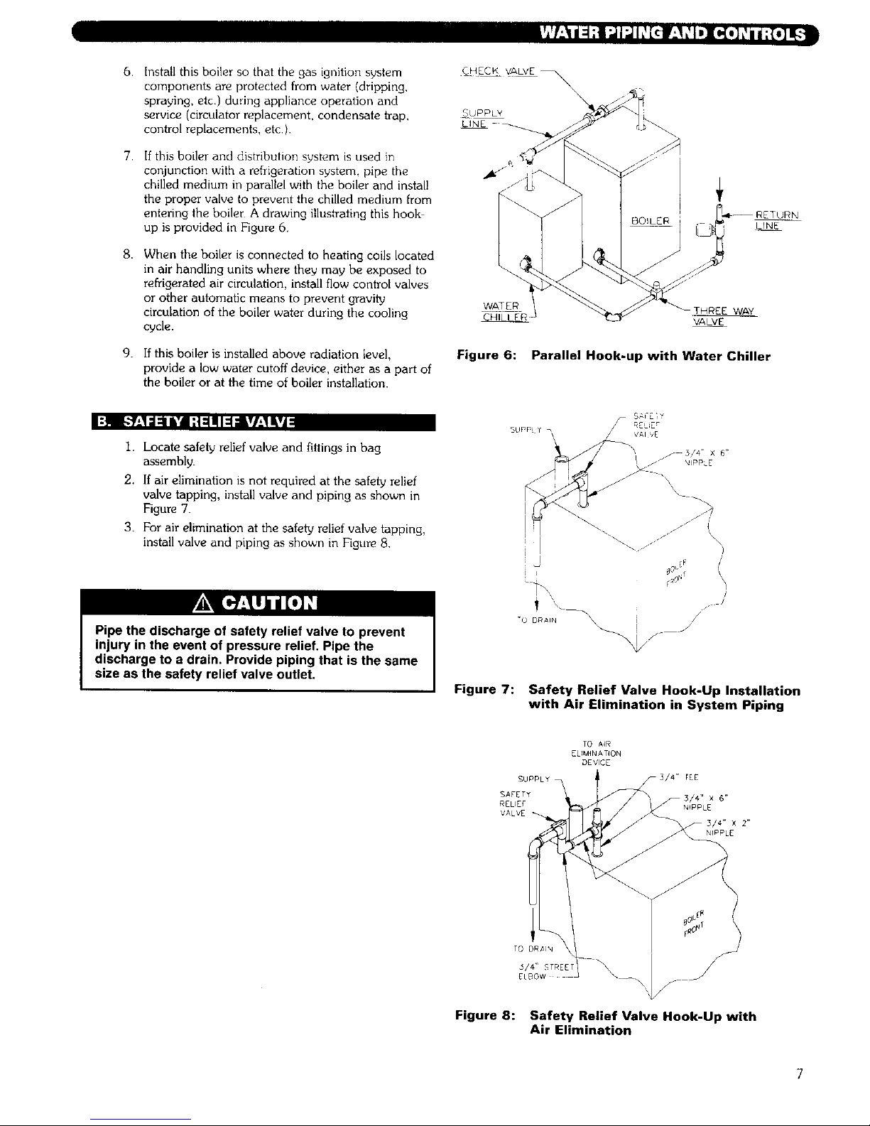
If this boiler and distribution system is used in
conjunction with a refrigeration system, pipe the
chilled medium in parallel with the boiler and install
the proper valve to prevent the chilled medium from
entering the boiler A drawing illustrating this hook
up is provided in Figure 6.
When the boiler is connected to heating coils located
in air handling units where they may be exposed to
refrigerated air circulation, install flow control valves
or other automatic means to prevent gravity
circulation of the boiler water during the cooling
cycle.
If this boiler is installed above radiation level,
provide a low water cutoff device, either as a part of
the boiler or at the time of boiler installation.
CHEEK VALVE _\
\
SUPPLY
LINE
LINE
WATER
[HREE WAY
VALVE
Figure 6: Parallel Hook-up with Water Chiller
I:_II R_,1:1=11&'dI;t :1111I=1;I lVl,_l&vA
1. Locate safety relief valve and fittings in bag
assembly.
2. If air elimination is not required at the safety relief
valve tapping, install valve and piping as shown in
Figure 71
3. For air elimination at the safety relief valve tapping,
install valve and piping as shown in Figure 8.
Pipe the discharge of safety relief valve to prevent
injury in the event of pressure relief. Pipe the
discharge to a drain. Provide piping that is the same
size as the safety relief valve outlet.
I
/./// \\
\
/
/
/
/
Figure 7: Safety Relief Valve Hook-Up Installation
with Air Elimination in System Piping
TO A4R
ELIMINATION
DEVICE
SUPPLY_ F3/4" tEE
SAFETY _3/4" X 6"
RELIE£ NIPPLE
VALVE
TO DRaiN
5/4" _TREET
ELBOW
Figure 8: Safety Relief Valve Hook-Up with
Air Elimination
Page 11
[o.]NI']l;,ll_[e'li_[_];t,,(o]_l_w]_._k'_J=hVJ_
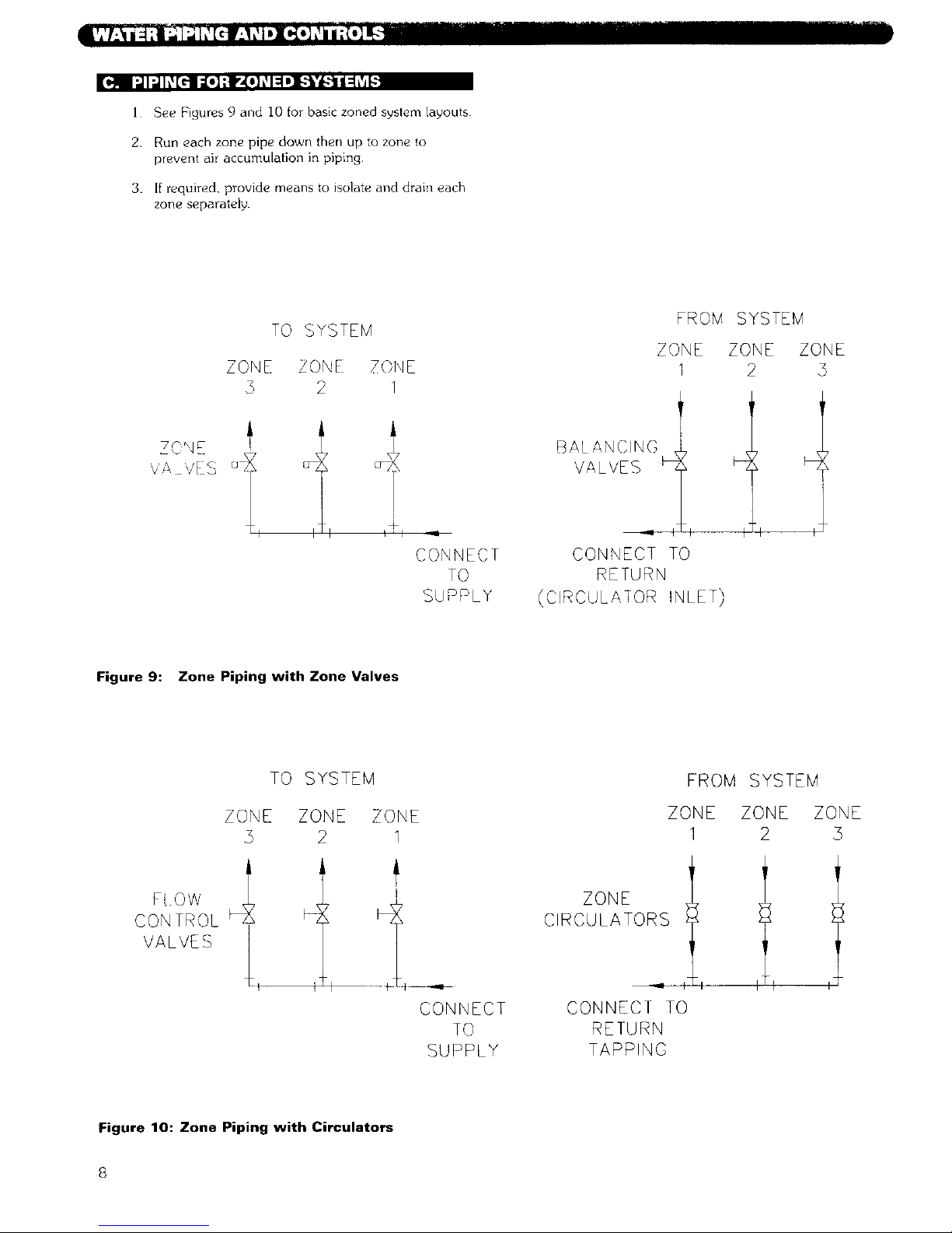
i See Figures 9 and I0 for basic zoned system layouts
2. Run each zone pipe down then up to zone to
prevent air accumulation in piping.
3. If required, provide means to isolate and drain each
zone separately.
TO SYSTEM
ZONE /O'qE
3 2 I
FROM SYSTEM
ZONE ZONE ZONE
1 2 5
Z S N E
'/A ,/E S °S
I
_h
CONNECT
TO
SUPPLY
BALANCING
VALVES
CONNECT TO
RETURN
(CIRCULAIOR INLET)
z
Figure 9: Zone Piping with Zone Valves
TO SYSTEM
ZONE ZONE ZONE
2 1
FROM SYSTEM
ZONE ZONE ZONE
1 2 3
CONTROL
VALVES
L
I
CONNECT
TO
SUPPLY
ZONE
CIRCULATORS
CONNECT TO
RETURN
TAPPING
Figure 10: Zone Piping with Circulators
8
Page 12
IlI I:).'4:1._IL'I_ [*] L'II _±Ib._I:
I'_ :t _ :_',4:l :J.*{._ i :_taj/ [.] k
Consult the tank manufacturer's instructions for
specific information relating to tank installation. Size
the expansion tank for the required system volume
and capacity See Table 10 in Section 10 for boiler
water capacity
2.
Expansion tanks are available with built-in fillvalves
and check valves for reducing supply water pressure
and maintaining minimum system pressure. Check
the design features of the tank and provide valves as
necessary.
Refer back to Figure 5 for typical expansion tank piping.
=lq h_l*] I:i::[,_l t_= I ;{ :ID]i_i_l_*_li :_;l I-"I:r_,'11:I:
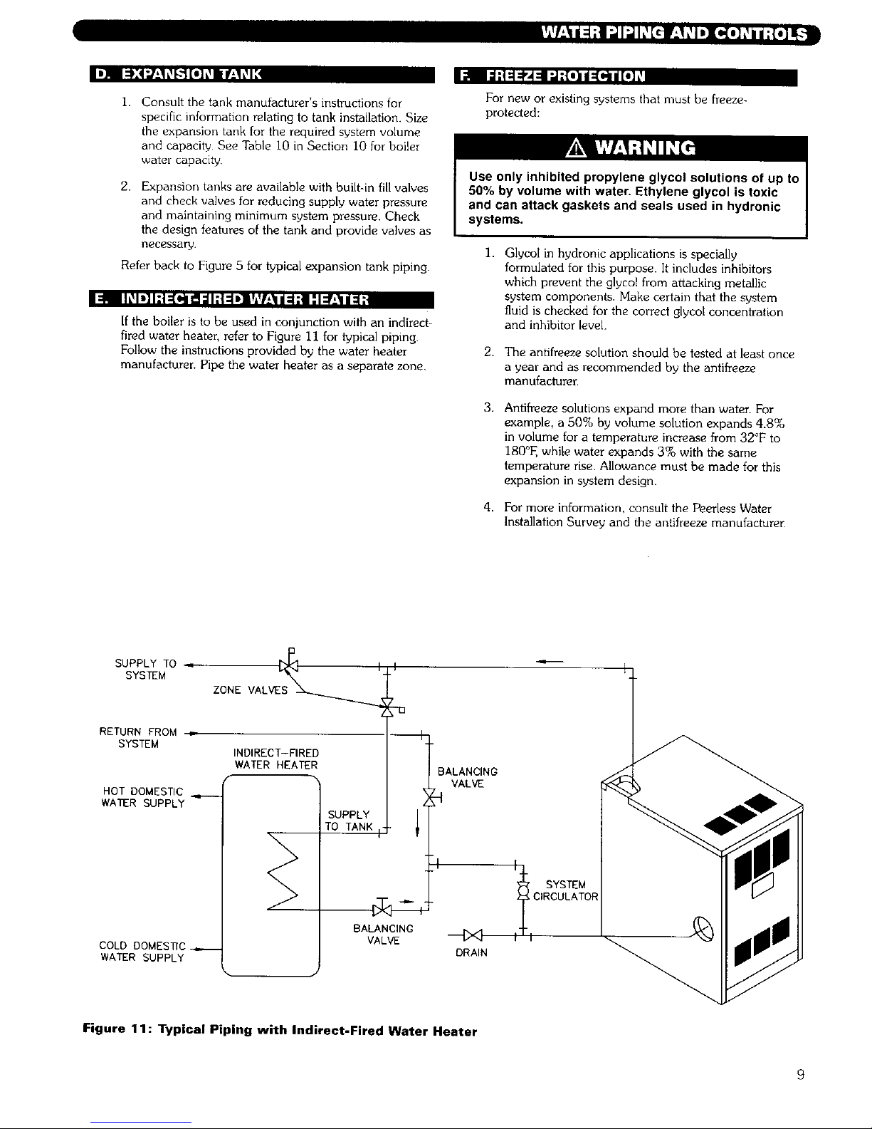
If the boiler is to be used in conjunction with an indirect-
fired water heater, refer to Figure 11 for typical piping.
Follow the instructions provided by the water heater
manufacturer. Pipe the water heater as a separate zone.
For new or existing systems that must be freeze-
protected:
Use only inhibited propylene glycol solutions of up to
50% by volume with water. Ethylene glycol is toxic
and can attack gaskets and seals used in hydronic
systems.
1.
Glycol in hydronic applications is specially
formulated for this purpose. It includes inhibitors
which prevent the glycol from attacking metallic
system components. Make certain that the system
fluid is checked for the correct glycol concentration
and inhibitor level.
2. The antifreeze solution should be tested at least once
a year and as recommended by the antifreeze
manufacturer.
3,
4.
Antifreeze solutions expand more than water. For
example, a 50% by volume solution expands 4.8%
in volume for a temperature increase from 32°F to
180°E while water expands 3% with the same
temperature rise. Allowance must be made for this
expansion in system design.
For more information, consult the Peerless Water
Installation Survey and the antifreeze manufacturer.
SUPPLY TO .
SYSTEM
RETURN FROM •
SYSTEM
HOT DOMESTIC ,.,___
WATER SUPPLY
COLD DOMES_C_
WATER SUPPLY
ZONE VALVE_
INDIRECT-FIRED
WATER HEATER
L
SUPPLY 1
TO TANK
BALANCING
VALVE
BALANCING
VALVE
DRAIN
17_ SYSTEM
i_1 CIRCULATOR
Figure 11: Typical Piping with Indirect-Fired Water Heater
Page 13

..kvi::I_iilT[_
-._ _ii. _: ./" :i
r±1 [€_:IL_I:I;Ir.'_
i.
2.
3.
Instal] vent system in accordance with Part 7, Venting
of Equipment. National Fuel Gas Code, ANSI
Z223.1/NFPA 54 or applicable provisions of the local
building codes
Do not connect vent connectors serving appliances
vented by natural draft into any portion of
mechanical draft systems operating under positive
pressure.
Refer to the following venting options to determine
which method is applicable.
I;]q ["]" IhvdL11::k'dkv4::1_/ i h_[_
If venting into a masonry chimney; chimney must be
lined with a fire clay tile liner or corrosion resistant metal
liner. Type B vent may also be used as a lining system or
as a stand alone chimney vent.
2.
3,
4.
5.
The vent system, when installed per the following
instructions, will operate with a negative pressure
(draft).
Horizontal portions of the venting system shall slope
upward at least I/4" per lineal foot between boiler
and chimney. The vent pipe shall be supported to
prevent sagging; using metal strapping or equivalent
means at no more than 4 ft. intervals.
Locate fan adapter, silicone, hardware and fan
adapter gasket in boiler miscellaneous parts box and
attach to blower outlet flange. Refer to Fig. 12 for
details.
Apply 1/4" bead of silicone around fan adapter and
slip increaser over the fan adapter. Refer to Table I
for increaser and chimney sizes. Increaser to be
provided by installer.
Single wall vent pipe should be furnished between
increaser and chimney. If the vent connector shall be
located in or pass through a cold area, the vent
connector shall be type B material.
Table 1: Increaser b Chimney Size
Vent Size
Boiler Model Increaser Size Diameter Chimney Size
DE-03 3" to 4" 4" 4" x 15
DE 04 3" to 5 5" 5" x 15
DE-05 3" to 5" 5" 5" x 15'
DE-06 3" to 5" 5" 5" x 15'
SLOPE UP 1/4"
PER FOOT_
I
SLOPE UP 1/4"
JACKETPANELS_ PER FOOT
ADAPTER
FAN _'f
ADAP_R GASKET _ "- INCREASER
1/4-20 NUT SILICONE
at WASHERSJ
MASONRY
CHIMNEY
Figure 12: Chimney Venting
-/
• • °
,., .,
• %
, . ,
a.
10
Page 14

Flue gases will condense as they exit the vent
termination. This condensate can freeze on exterior
building surfaces which may cause discoloration of
these surfaces.
1.
2.
3.
This vent system will operate with a positive pressure
in the vent pipe. Follow vent pipe manufacturers
instructions for proper assembly of vent pipe and
fittings.
Refer to Table 2 for minimum and maximum vent
length allowed.
Maintain a minimum 2" clearance between vent pipe
and combustible construction.
4.
When installing vent pipe through a combustible
wall, pipe must pass through a metal wall thimble;
maintaining a 2" clearance between vent pipe and
thimble.
5.
Determine vent terminal location.
a. Vent terminal shall be located at least 3 feet
above any forced air inlet located within 10 feet.
b.
Vent terminal shall be located at least 4 feet
below, 4 feet horizontally from, or i foot above
any door, window, or gravity air inlet into any
building.
c. Vent terminal shall be located at least I foot
above ground level or normal snow lines.
d. Vent terminal shall not be located over public
walkways where condensate could create a
nuisance or hazard.
e. When adjacent to a public walkway, vent
terminal shall be at least 7 feet above grade.
f. Vent terminal shall be located at least 4 feet
horizontally from electric meters, gas meters,
regulators and relief equipment.
g. Vent terminal should not be located directly
under roof overhangs to prevent icicles from
forming.
Table 2: Equivalent Vent Length
Boiler Model
DE 03
DE-04
DE 05
DE-06
*Equivalent Length of 3" diameter
Stainless Steel Vent Pipe
Minimum Vent Length Maximum Vent Length
2-1/2 feet 50 feet
2 1/2 feet 50 feet
2-1/2 feet 45 feet
2-1/2 feet 45 feet
6 Vent Pipe Assembly:
a. Horizontal portions of the vent pipe shall slope
down not less than I/4" per foot from the boiler
to the vent termination elbow. If this horizontal
run is pitched toward boiler, provide a horizontal
drain tee as per instructions in section D. Direct
Exhaust; Vertical Venting, of this manual
b.
The horizontal portions of the vent pipe shall be
supported to prevent sagging, by metal strapping
or equivalent means, located at no greater than 4
ft. intervals.
C.
d.
e.
g.
h.
Type vent material approved is AL29-4C, 3 inch
diameter stainless steel; manufactured by Heat-
Fab ® (Saf-T-Vent); Z-Flex ® (Z-Vent); ProTech
(FasNSeal'"); Flex-L (StaR-34).
Attach the fan adapter to blower outlet flange
using gasket and 1/4"-20 nuts and washers,
(parts located in miscellaneous parts box).
Refer to Figure 13 that lists special vent adapters
for connection to boiler fan adapter. These
special adapters are not supplied with boiler.
Attach vent pipe adapter to boiler fan adapter by
applying a 1/4" bead of high temperature silicone
around diameter of fan adapter and slip vent
pipe adapter over the fan adapter. Fill in any
voids with silicone and smooth out with
moistened finger on fiat tool.
If using Z-Flex ® pipe, slide vent pipe over the first
2-1/2" of the fan adapter and secure joint
connection with the Z:Flex ® looking bands
making sure that locking band has contact with
fan adapter at boiler end and vent pipe.
Attach remaining pipe and fittings per
manufacturer's vent instructions. Use only the
silicone recommended by the vent pipe
manufacturer.
i. The only approved vent termination is a 3" 90 °
elbow. Refer to Figure 14.
*Maximum Vent Length to be reduced by 5 feet
for each 90 elbow added that is manufactured by
Z-Flex ®, Heat-Fab ® and Protech.
*Maximum Vent Length to be reduced by 7-1/2
feet for each 90 elbow added that is
manufactured by Flex-L
The outside vent terminal (90 Elbow) is not
included in Equivalent Vent Length.
11
Page 15

Z-FLEX
Z-VENT
I-PIPE, MALE
END
HEAT-FAB
SAF-T VENT
PIPE,
MALE END
PROTECH
FASNSEAL
VENT PIPE,
MALE END
FLEX-L
STAR-34
VENT PIPE,
MALE END
S Z-FLEX _HEAT-FAB _ PROTECH
Z-VENT SAF-T VENT l FASNSEAL f
LOCKING 7501AMTK FSA-PSC/DE-3
SAND VENT ADAPTER VENT ADAPTER
SVSLBX05
!/4" BEAD
SILICONE 7
PEERLESS
FAN ADAPTER
I/4" BEAD 1/4" BEAD
n<
SILICONE •
L PEERLESS L_ PEERLESS
FAN ADAPTER FAN ADAPTER
FLEX L
STAR-54
SRAPPA5
VENT ADAPTER
1/4" BEAD
SILICONE 7
L PEERLESS
FAN ADAPTER
Figure 13: Vent Pipe Adapters
JACKET PANI
FAN
FAN ADAPTER
I/4-20 NUTS
& WASHERS
m_ _ COMBUSTIBLE
EXTERIOR WALL
WALL THIMBLE
SLOPE DOWN
2 MIN.
I/4" PER FOOT \ '_/_ [-CLEARANCE
? O.EL OW
VENT TERMINATION
_-8"
- FAN
ADAPTER
NT PIPE
ADAPTER
(SEE VENT PIPE
ADAPTER LIS]]NG)
- SILICONE
5" DIA.
VENT PIPE
Figure 14: Direct Exhaust; Sidewall Venting
12
Page 16

Iml m]I:t;:[O.]ltil _.'4 -"r_"lm_"']ti kVA=1;_lti[e,]r_,'WIvd =lk_IItih._[€"ll
1.
2.
3.
4,
This vent system will operate with a positive pxessure
in the vent pipe. follow vent pipe manufacturer's
instructions for proper assembly of vent pipe and
fittings.
Refer to Table 2 for minimum and maximum vent
length allowed.
Maintain a minimum 2" clearance between vent pipe
and combustible construction.
Follow instructions under section C. DIRECT
EXHAUST; HORIZONTAL VENTING items 6b
through 6h in this manual.
5
6
7.
Horizontal portions of the vent pipe shall slope up
not less than 1/4"' per foot from the boiler to the
vertical vent
Provide a horizontal drain tee in the horizontal vent
run. Use silicone drain hose with a 3" diameter loop
trap with a water seal Pipe to drain per local codes.
Refer to vent pipe manufacturer's instructions under
vertical venting section for recommendation for
penetration through floors and roofs.
8. Vent must terminate 12" above expected snow lines.
JACKET PANELS_
FAN
FAN ADAPTER GASKET
1/4-20 NUTS
& WASHERS
2" MIN.
CLEARANCE
FLOOR D
SLOPE UP 1/4".
PER FOOT
HORIZONTAL
FAN DRAIN TEE]
ADAPTER
!
(SEE VENT PIPE
ADAPTER LISTING)
SILICONE
-- ATTACH VENT
MANUFACTURERS
LISTED RAIN CAP
ASHING
3" DIA.
VENT PIPE
_- FIRESTOP
SILICONE HOSE
DRAIN TRAP
(FORM 3" DIA, LOOP)
Figure 15: Direct Exhaust Vertical Venting
13
Page 17

At the time of removal of an existing boiler, follow these
steps with each appliance remaining connected to the
common venting system placed in operation, while the
other appliances remaining connected to the common
venting system are not in operation:
a. Seal any unused openings in the common venting
system.
b,
Visually inspect the venting system for proper size
and horizontal pitch and determine there is no
blockage or restriction, leakage, corrosion and other
deficiencies which could cause an unsafe condition.
C+
Insofar as is practical, close all building doors and
windows and all doors between the space in which
the appliances remaining connected to the common
venting system are located and other spaces of the
building. Turn on any clothes dryers and any
appliance not connected to common venting system.
Turn on any exhaust fans, such as range hoods and
bathroom exhausts, so they will operate at maximum
speed, Do not operate a summer exhaust fan. Close
fireplace dampers.
d.
e.
g.
Place in operation the appliance being inspected.
Follow the lighting instructions Adjust thermostat so
appliance will operate continuously.
Test for spillage at the draft hood relief opening after
5 minutes of main burner operation Use the flame
of a match or candle, or smoke from a cigarette.
cigar, or pipe.
After it has been determined that each appliance
remaining connected to the common venting system
properly vents when tested as outlined above, return
doors, windows, exhaust fans. fireplace dampers and
any other gas-burning appliance to their previous
conditions of use.
Any improper operation of the common venting
system should be corrected so that the installation
conforms with the National Fuel Gas Code. When
resizing any portion of the common venting system.
the common venting system should be resized to
approach minimum size as determined using the
appropriate tables located in the chapter "Sizing of
Category I Venting Systems," in the current edition
of the National Fuel Gas Code.
14
Page 18

I. Sizeandinstallthegassupplypipingproperlyin
ordertoprovideasupplyofgassufficienttomeet
themaximumdemandwithoutunduelossof
pressure between the meter and the boiler.
2. Determine the volume of gas to be provided to the
boiler in cubic feet per hour. To obtain this value,
divide the Btu per hour rating (on the boiler rating
plate) by the heating value of the gas in Btu per
cubic feet. Obtain the heating value of the gas from
the gas supplien As an alternative, use Table 3 or 4
on the next page to obtain the volume of gas to be
provided to the boiler.
3. Use the value obtained above as the basis for piping
sizing. Size the gas piping in accordance with Table
5. Consult the National Fuel Gas Code for other
sizing options.
4. Locate the drop pipe adjacent to, but not in front of
the boiler.
5. Install a sediment trap. See Figure 16. Locate a tee
in the drop pipe at same elevation as the gas inlet
connection to the boilen Extend the drop pipe to a
pipe cap.
6. Install a ground joint union ahead of the gas control
assembly to permit servicing of the control. Some
local codes require an additional service valve when
using the combination gas controls. If your code
requires such a valve, a suggested location is shown
in Figure 16.
Use a pipe joint sealing compound that is resistant to
the action of liquefied petroleum gas. A non-resistant
compound may lose sealing ability in the presence of
this gas, resulting in a gas leak and fire or explosion
potential.
7. Check piping for leaks.
Use an approved gas detector, a non-corrosive leak
detection fluid or other leak detection method. If
leaks are found, turn off all gas flow and repair as
necessa_
I
t
J
i
s Rv C_E
-"-VALVE
.------ dACKET
G.J. UNION
/ SEDIMENT TRAP
/FLOOR LINE
Figure 16: Gas Connection to Boiler
8. Disconnect the boiler and its individual shut-off valve
from the gas supply piping system during any
pressure testing of that system at test pressure in
excess of I/2 psig (3.5 kPa).
Do not subject the gas valve to more than 1/2 psi
pressure. Doing so may damage the valve.
Isolate the boiler from the gas supply piping system
by closing its individuM service valve during any
pressure testing of the gas supply piping system at
test pressure equal to or less than I/2 psig (3,5 kPa).
9. Minimum permissible supply pressure for purposes of
input adjustment (Inches Water Column):
Natural Gas 5.0"
LP Gas 11.0"
Maximum permissible supply pressure to the boiler
(Inches Water Column):
Natural Gas 13.5"
LP Gas 13.5"
When checking for leaks, do not use matches,
candles, open flames or other methods that provide a
source of ignition.This can ignite a gas leak,
resulting in fire or explosion.
15
Page 19

Table 3: Natural Gas
Model Input
(Cubic Ft/Hr)
DE-03 70
DE-04 105
DE 05 140
DE-06 165
Based on I000 BtulCubic Ft
Table 4: LP Gas
Model Input
(Cubic Ft!Hr)
DE-03 28
DE 04 42
DE-05 56
DE-06 66
Based on 2500 Btu/Cubic Ft.
Table 5: Pipe Capacity
Capacity of pipe of different diameters and lengths in cu, ft. per
hour with pressure drop of 0.3 in. and specific gravity of 0.60.
No allowance for an ordinary number of fittings is required.
Pipe a/4_ 1" 11/4" 11/2_
Length
Feet Pipe Pipe Pipe Pipe
10 278 520 1,050 1,600
20 190 350 730 1,100
30 152 285 590 890
40 130 245 500 760
50 115 215 440 670
60 105 195 400 610
Multipliers to be used with the above table when the
specific gravity of the gas is other than 0.60:
Specific Gravity . . .0.5 0.55 0.60 0.65 0.70
Multiplier ........ I.I0 1.04 1,00 0.962 0.926
16
Page 20

Install all electrical wiring in accordance with the National Electrical Code and local requirements.
This unit when installed must be electrically grounded in accordance with the requirements of the authority
having jurisdiction or, in the absence of such requirements, with the current edition of the National Electrical
Code, ANSI/NFPA 70.
h_! i_=_il;]lk_[_
1. SeeFigure 17 forlocation of wiring and controls.
Use Figure 18 to connect the boiler to a power
supply and to connect components to the boiler.
2. Connect the boiler by a separate, permanently live
electrical supply line with a fused switch.
3. Adjust the thermostat heat anticipator to 0.2 Amp.
I;]ii Ir_[e]k_l:=lD]i_"¥*d[-:tll:l_vi|r_li;,llL'
1) _LL _RIN_ _U_T ¢O_pL_ _ APPU^_CE O3OE_ O_DINANC[_ _O REGULAI_ON_
2) I_ ,_Ny O: _E O_qQNAL _£ A_ SUPPLIEO V_ _ _PPUANC£ _$T BE
RE_L_QEO. IT _U_T e_ REPLACED _ Va_ _S _OW_
(_OT}
R_L_Y
¢_L
HI_ W
C_ _ LI_IT
I_NII TM FLAME
_ esR_lttD
-- _20V _IN_ TUBIN¢)
.... 24V _N¢
Figure 18: Wiring and Connection Diagram
I _l/.'-] :[o]l J:1_[H :l[o] :lo]':,1:1;_:_1d[_]_
1. Thermostat calls for heal energizes R8285 Control
Relay (CR).
2. R8285 Con_ol Rela_ (CR) energizes circulator.
3. Limit senses boiler water temperature. PreventS
boiler operation until water temperature falls
approximately 15°F below the cut-out temperature.
4. Limit energizes Fan and R4222 Isolation Relay (IR).
5. Negative pressure induced by [an switches Pressure
Switch, continuing power through closed R4222
contacts (IR-I) and flame roll-out switch.
6. Gas valve energizes.
a. Igniter on.
b. Pilot gas on, igniting pilot.
7. Pilot flame detected.
a. Igniter off.
b. Main gas on, igniting main burners.
Note: If pilot flame is not detected within 30 seconds,
the igniter is turned off for 30 seconds, and then turned
back on. If the pilot is not detected within 30 seconds,
the igniter and pilot gas are turned off for 5 minutes.
The sequence then resumes at Step 6a.
8. Call for heat ends.
a. Pilot and main gas off, extinguishing pilot and
main burners.
b. Fan and circulator off.
18
Page 22

I=1al=[o,]i_,_T_li
START
TRIAL
FOR
IGNITION
L
MAIN
BURNER
OPERATION
t APPLY 24 VAC I
TO APPLIANCE
LTHERM°STATI
CALLS FOR HEAT
I FLAME SIGNAL
DETECTED_ NO
I INTERNAL CHECK OKAY? t NO
_YES
I • PILOT VALVE OPENS I• IGNITER POWERED
PILOTLIGHTSAND FLAME NO
IS SENSED DURING A_[TRIAL FOR IGNITION?
YES
• IGNITER OFF ]• MAIN VALVE OPENS
I
• WAIT FOR FLAME SIGNAL
TO DISAPPEAR
• PILOT VALVE/IGNITER
REMAIN OFF
]
• PILOT VALVE CLOSES
• IGNITER OFF
[
END
_r
i FLAME SIGNAL LOST? _-_
_NO
i THER"OSTATCALLFORIHEATENDS
I • MAIN AND PILOT VALVES CLOSE
• MAIN AND PILOT VALVES CLOSE
FLAME LOST MORE THAN
FIVE TIMES IN ONE
CALL FOR HEAT?
J 1
/_ IGNITER WILL TURN OFF ABOUT 30 SECONDS INTO THE TRIAL FOR IGNITION.
IF THE PILOT FLAME HAS NOT LIT, IT WILL TURN BACK ON FOR THE RNAL
30 SECONDS OF THE 90 SECOND TRIAL FOR IGNITION. THE PILOT VALVE
WILL BE ENERGIZED DURING THE ENTIRE TRIAL FOR IGNITION. THIS IS
NORMAL OPERATION FOR THIS GAS IGNITION SYSTEM.
I IVE-MINUTE RETRY
DELAY
Figure 19: Ignition System Operating Sequence
19
Page 23

© ©
I
I
I
..... LOW VOLTAGE
--. LINE VOLTAGE
NOT_
WIRING MUST COMPLy WITH ApFFICAB__ _
COD_S • ORDINANCE5, AN0 REGULATtO_
Figure 20: Zone Wiring with Zone Valves
120V- _OHZ
TO MAIN
OISCONN£CT
f f
d_
I
I
Z
TRANSFORMER
..... LOW VOLTAGE
-- LIN[ VOLTAG f.
ALt. WIllING k_JST ¢OUFLy WITH APPLICA_.E
COOES • OROTNANCIE S. ANO R£GULATION_.
Figure 21: Zone Wiring with Circulators
2O
Page 24

r,_1 [Ke]_VJl'Jl!:lllll_[€_ illl,'l:l Ih_-'-]lV'_1111r'__l/[e]_
i. Confirm that all water, gas and electricity are
turned off.
2. Inspect the boiler combustion chamber for foreign
objects and remove if present.
3. Check physical condition of burners and pilot• Make
certain that there are no unusual bends or
perforations in the burners or pilot. Replace
components if necessary.
4. Verify that water piping, venting, gas piping and
electrical wiring and components are installed
properly. Refer back to previous sections of these
instructions as well as equipment manufacturer's
instructions as necessary.
5. Fill the boiler and system with water, making certain
to vent all air from all points in the system. To check
water level in the system, open and close each vent
in the system. Water should exit from each vent
when it is opened.
6. The pressure reducing valve on the fill line will
typically allow the system to be filled and pressurized
to 12 psi. Consult the valve and expansion tank
manufacturer for more specific information.
7. Check joints and fittings throughout the system for
leaks. If leaks are found, drain the system and repair
as required.
8. Connect a manometer to the gas valve inlet pressure
tap. See figure 23.
9. Confirm that the gas supply pressure to the boiler is
above the minimum and below the maximum values
for the gas being used. See the end of Section 5 for
these values• If a supply pressure check is required•
isolate the boiler and gas valve before performing
the pressure check. If the supply pressure is too high
or too low, contact the gas supplier
10. Turn on electricity and gas to boiler.
11. Light the boiler by following the Lighting/Operating
Instructions label mounted to the jacket panel. The
initial ignition may require several tries as the piping
is purged of air.
12. Use the sequence descriptions in Figures 18 and 19
in Section 6 (Electrical) to follow light-off and
shutdown sequences and to assist in diagnosing
problems. If the boiler does not function properly,
consult Section 8, Troubleshooting.
13. The gas manifold and control assembly are made of
gas-tight, completely factory assembled and installed
components of the base assembly• See Figure 22
and 23.
21
Page 25

STEEL
A÷-I / BURNER
_ ORiFtCE
_ '_ MANIFOLD
A_ _-TEST TAPPING
VALVE
PILOT
PII OT TUBING
SECTION A A
Figure 22: Gas Valve, Manifold and Burner Assembly - intermittent Ignition
INLET
PRESSURE
TAP --
INLET
GAS PRESSURE REGULA!OR
ADJUSTMENT SCREW
(UNDER CAP SCREW)
F OUTLET PRsSSURE TAp
\ --J 0
I_ _OUTLET
\ LLIj%II IL
CONNECTION (UNDER CAP SCREW)
(STANDING
PILOT ONLY)
NOTE: LOCATPONS ARE SIMILAR FOR STANDING
PILOT AND INTERMITTENT IGNITION VALVES
Figure 23: Valve Tapping and Adjustment Screw Locations
22
Page 26

---- b ' iI " "_ e • , ....
FOR YOUR SAFETY READ BEFORE OPERATING
A.
I WARNING: If you do not follow these instructions exactly, a fire or explosion may result I
I
causing property damage, personal injury, or loss of life.
I
This appliance is equipped with an ignition device • If you cannot reach your gas supplier, call the fire
which automatically lights the pilot. Do not try to
light the pilot by hand. department.
g. BEFORE OPERATING smell all around the
appliance area for gas. Be sure to smell next to the
floor because some gas is heavier than air and will
settle on the floor,
WHAT TO DO OF YOU SMELL GAS
• Do not try to light any appliance.
• Do not touch any electric switch;
do not use any phone in your building.
• Immediately call your gas supplier from
a neighbor's phone. Follow the gas
supplier's instructions.
C.
Use only your hand to slide the gas control switch
Never use tools. If the switch will not slide by hand,
don't try to repair it, call a qualified service
technician. Force or attempted repair may result in a
fire or explosion.
g.
Do not use this appliance if any part has been under
water. Immediately call a qualified service technician
to inspect the appliance and to replace any part of
the control system and any gas control which has
been under water.
OPERATING INSTRUCTIONS
1. STOP! Read the safety information above on this
label.
2. Set the thermostat to the lowest setting.
3. Turn off all electric power to the appliance.
4. This appliance is equipped with an ignition device
which automatically lights the pilot. Do not try to
light the pilot by hand.
_GAS CONTROL
SWITCH
OUTLET _11 _11 INLET
5.
6.
Ifthe gas valve is not visible, remove control access
panel.
Ifthe gas control switch is not in the "OFF" position,
slide the switch to "OFF".
7. Wait five (5) minutes to clear out any gas. If you
then smell gas, STOP! Follow "B" in the safety
information above this label If you don't smell gas,
go to the next step.
8, Slide the gas control switch to "ON".
9. Replace control access panel, if applicable.
10. Turn on all electric power to the appliance.
11. Set the thermostat to desired setting.
12. If the appliance will not operate, follow the
instructions "To Turn Off Gas To Appliance" and call
your service technician or gas supplier.
1,
2.
3.
TO TURN OFF GAS TO APPLIANCE
Set the thermostat to lowest setting. 4. Slide the gas control switch to "OFF".
Turn off all electric power to the appliance if service 5. Replace control access panel, if applicable.
is to be performed.
If the gas valve is not visible, remove the control
access panel, sv95011sv96018318
Figure 24: Operating Instructions
23
Page 27

:II [a'[O]L'_ilI-'{O]IID]=[',."[O"]-'II_II[O]L'IF+-
See Figure 17 in Section 6 (Electrical) for locations of
these devices.
I.
FLAME ROLL-OUT SAFETY SHUT-OFF SWITCH
(FLAME ROLL OUT SWITCH) A thermally
activated switch located between the first burner
from the left and the manifold bracket. The flame
roll-out safety shut+off switch will sense excessive
temperature caused by continued flame roll-out and
shut down main burner gas. This is a non-recycling
switch that must be replaced once it has been
activated and the cause of the roll-out eliminated.
2.
DJ [q:l=[q[4h_[ct I:ieJ;t_l=l;_ ll++'_l',,,,tlj
3.
4,
PRESSURE SWITCH A pressure sensing device
that is located in the jacket vestibule. This control
senses a suction pressure when fan is energized on a
call for heat. Switch contacts close allowing control
circuit to energize ignition system.
LIMIT (AQUASTAT) A thermally activated,
manually adjustable switch located on the left side of
the boiler, towards the top and rear. The temperature
sensing element is placed in the supply and will shut
down main burner gas if the supply water exceeds
the preset temperature limit. This is a recycling
switch that will automatically reset when the supply
water falls below the preset temperature.
LOW WATER CUT-OFF (FOR GRAVITY SYSTEMS
OR HOT WATER BOILERS INSTALLED ABOVE
RADIATION LEVEL) - A level-sensing device (float
or probe) located in supply piping near the boiler. If
water level in the system drops below the control's
position, it will shut down main burner gas. The
control will automatically reset once the water level
rises above its position.
2.
3.
4.
To adjust gas pressure, turn adiusfing screw of gas
pressure regulator counterclockwise to decrease
pressure, clockwise to increase pressure. Refer to
Figure 23 for location of gas pressure regulaton
Replace the cap screw when adjustment is complete
In no case should the final manifold pressure vary
more than +0+3 inches water column flora the
above specified pressures. Any necessary major
changes in the flow should be made by changing the
size of the burner orifice spuds.
When adjustment is complete, turn off boiler, gas
flow and electricity to boiler. Remove manometer
connection from valve and plug tapping with plug
provided. Turn utilities back on and resume
checkout.
I. Refer to rating label mounted on the jacket top panel
to obtain the rated BTU per hour input. In no case
shall the input to the boiler exceed the value shown
on the rating label.
2. Check input by use of the following formula
(Peerless suggests reading meter for 2 Cu.Ft.):
3.
BTU/Hr. Input-3600 x F x H
T
3600 - Seconds per hour
F - Cubic Feet of Gas Registered on Meter
H Heat Value of Gas in BTU/Cubic Feet
T - Time in Seconds the Meter is Read
As an alternative, use Table 6+ Use the heating value
provided by gas supplier. Use a stopwatch to record
the time it takes for 2 cubic feet of gas to pass
through the meter. Read across and down to
determine rate.
1. Connect a manometer to 1/8 N,R'E tapping on gas
manifold, set manifold pressure as follows for various
gases.
a+ Natural Gas .......... 3.5" Water Column
b. LP Gas ............ 10.0" Water Column
24
Page 28

Table 6: Meter Conversion - Natural Gas
Burner inputs in Btu/hr for various meter timings and
heat values. (Tables based on 2 cubic feet of gas through
meter).
Time that Heat Value of Gas
meter is (Btu!cubic foot)
read (sec) 1000
25 288000
30 240000
35 205714
40 180000
45 160000
50 144000
55 130909
60 120000
65 110769
70 102857
75 96000
80 90000
85 84706
90 80000
95 75789
100 72000
105 68571
110 65455
115 62609
120 60000
125 57600
1025 1050
295200 302400
246000 252000
210857 216000
184500 189000
164000 168000
147600 151200
134182 137455
123000 126000
113538 116308
105429 108000
98400 100800
92250 94500
86824 88941
82000 84000
77684 79579
73800 75600
70286 72000
67091 68727
64174 65739
61500 63000
59040 60480
I=1! [_:l:(q:fIIlll/I:J;{ole4::lIlllH
1. After starting the boiler, be certain all controls are
working properly. Check to be sure that the limit will
shut off the boiler in the event of excessive water
temperature, This can be done by lowering the limit
setting until the main burners shut down. When
proper limit function is confirmed, return the dial to
its previous setting.
2. To check operation of the ignition system safety
shut-off features:
a. Turn gas supply off.
b. Set thermostat or controller above room
temperature to call for heat. Watch for igniter
glow at pilot burner.
c. Igniter will continue to glow for 30 seconds, de
energize for 30 seconds, then re-energize and
glow for another 30 seconds. It will then de
energize for 5 minutes before restarting the
sequence.
d Turn gas supply on.
e. Reset the boiler and control by following
Operating Instructions.
f. Observe boiler operation through one complete
cycle.
3.
4.
5.
6.
7.
8.
Low Water Cut-Off (if used) - Consult the
manufacturer's instructions for the low water cut off
operational check procedure.
Check the system to make sure there are no leaks or
overfilling problems which might cause excessive
make up water to be added. Make-up water causes
liming in the boiler and brings in oxygen. Oxygen
can cause severe damage to the boiler though
oxygen corrosion pitting.
Check the expansion tank and automatic fill valve (if
used) to confirm that they are operating correctly. If
either of these components causes high pressure in
the system, the boiler relief valve will weep or open,
allowing fresh water to enter the system.
Do not allow the system controls to subject the boiler
to excessively low water temperatures, which would
cause condensation of flue gases and corrosion of
the boiler. Operate the boiler at a temperature above
130°E Adjust the boiler limit as required to maintain
boiler temperature above this level.
Check the general condition of the system including
piping support, joints, etc. Check cleanliness of the
radiators, baseboard units and/or convectors. Clean
them to the extent possible. If radiators do not heat
evenly, vent any remaining air from them.
Review operation and User's Information Manual
with end-user.
9. Complete the Warranty Card and submit it to
Peerless Heater Company.
10. Hang the Installation, Operation and Maintenance
Manual and User's Information Manual in an
accessible position near the boiler.
25
Page 29

In the event of a shut-down caused by a pilot outage,
action of the pressure switch or flame roll-out safely
shut-off switch effecting a shut-down of the main
burners:
a. Refer to the Operating Instructions in Figure 24 to
properly turn off the gas to the boiler
b. Turn off all electric power to the boiler.
c. Call a qualified heating service organization or local
gas company and have the cause of the shut-down
investigated and corrected.
d. Refer to Operating Instructions to
re-start boiler.
I:]! b|:TeliJ;]E::_']-'[ele_ldlL_[_fl [€-lille]:_
Use Table 8 to assist in determining causes and
providing corrective actions to boiler problems. Refer
also to Figure 26 to troubleshoot the Intermittent Ignition
System Control. These guides must be used only by
qualified service technicians. These individuals must
follow al! applicable codes and regulations in repair of
any boiler problems.
[Ill IL'_I:F*__-'tiI;HL_[Cl_."tele,i/[e]_ I;J;I:_.'_.'tUJ;t
Refer to Table 7 for fan suction pressure required to
energize control circuit. Measure fan suction pressure as
shown in Figure 25. Note that as boiler operates, suction
pressure will decrease. Measure after 15 minutes of
boiler operation.
When servicing or replacing items that communicate
with the boiler water, be certain that:
• There is no pressure on the boiler.
• The boiler is not hot.
• The power is off.
When servicing the gas valve or pilot, be certain that:
• The gas is off.
• The electricity is off.
Do not use this appliance if any part has been under
water. Improper or dangerous operation may result.
Immediately call a qualified service technician to
inspect the boiler and to replace any part of the
control system and any gas control which has been
under water.
Label all wires prior to disconnection when servicing
controls. Wiring errors can cause improper and
dangerous operation. Verify proper operation after
servicing.
Should overheating occur or the gas supply fail to
shut off, do not turn off or disconnect the electrical
supply to the pump.This may aggravate the problem
and increase the likelihood of boiler damage. Instead,
shut off the gas supply at a location external to the
appliance.
Table 7: Fan Suction Pressure
Boiler Model Suction Pressure
I (In. w.c)
DE-03 1.78
DE 04 1.56
DE-05 1.56
DE-06 1.35
26
Page 30

TO PRESSURE TAP
FITTING CLOSEST TO
FLUE COLLECTOR
I/8" SILICONE
LOW NEG.
PRESSURE
TAP-
1/8" TEST
-HI NEG.
PRESSURE TAP
TO PRESSURE
TAP FITTING
CLOSEST TO FAN
1/8" TEST TEE
1/8" SILICONE
TUBING
1/8" TEST
TUBING
PRESSURE SWITCH
INCLINED MANOMETER
0-2" W.C.
MINIMUM SUCTION PRESSURE:
SEE TABLE 7
Figure 25: Procedure For Measuring Fan Suction Pressure
27
Page 31

Table 8: Boiler Troubleshooting Guide (Burners Functioning)
Burners not functioning
Burners will not shut
down
Flashback or burning
at orifice spuds
Delayed ignition.
Condensation at boiler
vent connector/fan•
See Figure 26
i Defi,cflve gas valve
2. Short circuit.
1. Manifold gas pressure too low.
2 [mproperly sized/drilled orifice spuds.
3 Leaking gas valve.
4. Burrs on orifice
5. Low supply gas pressure,
1 Insufficient pilot flame.
2. Pilot burner/orifice clogged.
3. Overfiring,
4. Misaligned burners or pilot
1. Vent pipe not sloped towards vent terminal•
See Figure 26
i Use Figure 26 to troubleshoot intermittent
ignition gas valve Replace if necessary.
2 Check and correct wiring
] Adjust to proper pressure
2 Install correct spuds.
3. Replace valve.
4. Remove burrs.
5. Contact gas supplier if natural gas Adjust
regulator if LP gas.
1 Increase pilot gas flow.
2, Clean pilot burner and orifice
3. Reduce rate to input on rating label•
i 4. Realign burners or pilot
i
i
I. Install condensate _'ap per vent manufacturer's
instructions.
2. Slope vent pipe towards vent terminal.
Boiler not heating i
properly, i
i
Fumes or gas odors
1. Underfiring.
2 Limit set too low.
3. Air in system.
4. Circulator malfunctioning.
5. Circulation system clogged
6 Incorrect thermostat heat anticipator setting.
1, Increase rate to input on rating label.
2. Reset limit to higher setting.
3. Vent air from all points in system,
4. Check circulator, replace if necessary.
5. Shut down and cool boiler, drain and flush
system•
6. Adjust heat anticipator.
I Leaks in gas piping or fittings,
2. Leaks in gas service line or meter
3. Obstructed chimney.
4. Obstructed flueways or vent.
5. Draft problem in boiler room.
6. Overfiring.
I Locate and repair or replace
2. Shut down boiler and notiO gas provider.
3. Check, repair and!or clean chimney.
4. Clean flueways or vent and remove obstructions.
5. Check air supply, ventilation and venting system•
7. Reduce rate to input on rating label•
28
Page 32

t_
h_
P.
m
o
0
O"
3"
in
o
o
_Q
.=.
Q.
0
_t
Z
o
PF
"n
o
=.
DO BURNERS
FUNCTION?
NO
BOESIGNm_R WARM YES
DP AND GL_V RED?
(INTERMffTENT_
Is FAN RUNNING?
NO
_f
SEE TABLE 8 ]
1) CHECK FOR 24VAC AT PRESSURE
SWITCH ',NO" TERMINAL TO GROUND.
IF NO VOLTAGE, CHECK FOR:
. BLOCKED OR CRACKED SUCTION
TUBING.
. FAN NOT GENERATING ADEQUATE
SUCTION PRESSURE.
• DEFE_rlVE PRESSURE SWITCH.
2) CHECK FOR 2/VAC AT p4222 RELAy
BLUE WIPES TO GROUND:
- IF NO VOLTAGE AT EITHER BL WIRES.
CHECK FOR BROKEN/LOOSE WIRE.
. IF NO VOLTAGE AT ONL¥ ONE BL WlRE.
CHECK FOR 120VAC BETWEEN R4222
RELAy BLACK AND WHITE W1RES. IF
SO. RELAy IS DEFECTIVE.
3) CHECK FOR 24VAC AT FLAME ROLL*OUT
BW1TCH, IF SWITCH IS BLOWN. CORRECT
CAUSE OF ROLL*OUT BEFORE
REPLACING SWITCH.
FOR NEATI • TURN OFF GAS SUPPLY
• ASSURE GAS VALVE SWITCH IS
IN "ON" pOSITION
• DISCONNECT SYSTEM CONTROL
HARNESS
• SET THERMOSTAT TO CALL
S CNEC'ORPRDPORVOLTAGE0NECK
AT CONTROL HARNESS {SEE INSET • LINE VOLTAGE pOWER
A)* VOLTAGE SHOULD BE 24V * LOW VOLTAGE TRANSFORMER
BETWEEN THERMOSTAT AND • LIMIT CONTROLLER
24V COMMON, AND 24V BETWEEN • THERMOSTAT
24V COMMON AND 24V HOT. •WIRING
YES
UNPLUG pILOT BURNER CABLE.
I IGN_'rER WARMS UP AND _ MEASURE VOLTAGE AT GAS VALVE
GLOWS RED HSI ELEMENT OUTPUT (SEE INSET B)
24V NOMINAL
+ YES
] IREPLACEGNOE PLAMERODASSSMBL¥1
RECONNECT PILOT BURN[R CABLE
1[ YES
l _'ORRECT
THERMOSTAT
pI_BLEM
JUMPERTHERMOSTAT NO_ REpLACELIMITCONTROL
AT CONNECTIONS CHEC K FOR 120VAC HIGH LIMIT CONTRO L.IF
"G" AND "y" ON R8285. pOWER ATONETERMINAL BUT NOTBOTH,
DOES BOILER RUN?
•CHECK FOR 24VAC AT PRESSURE SWITCH
J TERMINALS "C" AND "N C" TO GROUND:
OlF VOLTAGE AT "N C" BUT NOT 'C",
PRESSURE swFrcH IS STUCK IN
RUNNING POSITED N. CHECK FOR BLOCKED
AIR TUBE. IF OKAy, REPLACE pRESSURE
S'01_TCH,
elF NO VOLTAGE AT EITHER PRESSURE
SWITCH TERMINAL "C" OR "NO _ TO
GROUND, CHECK FOR 120VAC INCOMING
pOWER INSIDE JUNCTION BOX, IF PROPER
INCOMING POWER, REPLACE R8285.
YES
L
I • TURN ON GAS SUPPLY
• piLOT BURNER LIGHTS
YES
L
IMANV'LVEOPEN AND
MAIN BURNER UGHTS
I YES
L SYSTEM iS OKAY l
INSET A
END VIEW OF
24 VOLT CO NTROL
TA HARNESS
THERMOS T CONNECTOR
VOLTS
24 VOLT V T
COMMO 24 GL
VOLTS HOT
CHECK FOR DAMAGED OR MISSING
TERMINALS IN CONNECTOR
INSET B
• CHECK THAT PILOT GAS IS FLOWING.
WAIT TO ASSURE PILOT GAS TUBING
IS PURGED.
_ YES
• MEASURE VOLTAGE BETWEEN 24V
HOT AND 24v COMMON LEADS TO GAS
VALVE. MUST MEASURE AT LEAST
19+_ VAG WITH IGNITER pOWERED.
SEE INSET A TO IDENTIFY PROPER
LEAD. THIS CHECK MUST BE DONE
WITH THE GAS VALVE CONNECTED
AND IGNITER pOWERED.
_ YES
REPLACE GAS VALVE ]
lREDONNECTP'LOTBDROOR1CABLE
REPLACE IGNITER/FLAME ROD ASSEMBLY I
REPLACEIGNITER/FLAME ROD ASSEMBLY J
• CHECK 1"HAT PILOT FLAME MAKES _1 iOGOOD CONTACT WITH PILOT BURNER
CYCLE THER STAT OFF AND _ACK ON I
FLAME ROD
• CHECK FOR GOOD ELECTRICAL
CONNECTION THROUGH THE PILOT
TOO,NG I I I
• IF BOTH OF THE ABOVE ARE GOOD, IF MAIN BURNERS DO NOT LIGHT,
REPLACE iGNITER/FLAME ROD REPLACE GAS VALVE
ASSEMBLY.
Page 33

I.
2.
3.
4.
Disconnect this boiler from the gas supply piping
during any pressure testing of the gas system.
Check pipes adjacent to cold walls or in unheated
spaces. Insulate and tape them if necessary to be
sure they can't freeze up. Keeping the water moving
at all times will reduce the likelihood of freezing. See
Section 3 for antifreeze instructions.
If there is considerable foreign matter in the boiler
water, the boiler should be shut down and allowed to
cool, then drained and thoroughly flushed out. Use
the drain valve at the bottom of the return
connection to drain the boilen Pipe the drain cock to
a suitable drain or containment device if antifreeze is
used. Flush the system to remove remaining matter.
If there is evidence that hard scale has formed on the
internal surfaces, the boiler should be cleaned by
chemical means as prescribed by a qualified water
treatment specialist.
There must not be signs of continuous wetness at the
chimney. If signs of continuous wetness are
observed, a qualified service agency must be
consulted to modify the vent configuration to prevent
the formation of condensate.
I:m Iw7-_11k'd YA_l//-'ll:(o]ll_;lll_lLll-:'t:
Daily boiler observation can be performed by the owner.
If any potential problems are found, a qualified installer
or service technician/agency must be notified.
I.
Remove any combustible materials, gasoline and
other flammable liquids and substances that generate
flammable vapors from the area where the boiler is
contained. Make certain that the boiler area has
ample air for combustion and ventilation and that
there are no obstructions to the free flow of air to
and from the boiler.
2.
3.
Observe general boiler conditions (unusual noises,
vibrations, etc.)
Observe operating temperature and pressure on the
combination gauge located on the left side of the
boiler. Boiler pressure should never be higher than
5 psi below the rating shown on the safety relief
valve (25 psig maximum for a 30 psig rating, 46 psig
maximum for a 50 psig rating). The valve rating can
be found on the top of the safety relief valve (see
Figure 5 for location of the safety relief valve). Boiler
temperature should never be higher than 250 ° E
4. Check for water leaks in boiler and system piping.
5. Smell around the appliance area for gas. If you smell
gas. follow the procedure listed in the Operating
Instructions in Section 7.
[*fllYjvj :1:1_qk'm|IivJi |: l :[o] I 1:1:g h_gl_:
1. Flush float type low-water cut off (if used) to remove
sediment from the float bowl as stated in the
manufacturer's instructions.
I J]lliVA[o] _/ /: Ik'4Lvl_J/ i: I :To]II1:1;g IL_l I_1 _
I. Check boiler room floor drains for proper
functioning.
2. Check function of the safety relief valve (monthly
unless specified otherwise by manufacturer) by
performing the following test:
a. Check valve piping to determine that it is
properly installed and supported.
b. Check boiler operating temperature and pressure.
c. Lift the try lever on the safety relief valve to the
full open position and hold it for at least five
seconds or until clean water is discharged.
d.
Release the try lever and allow the valve to close
If the valve leaks, operate the lever two or three
times to clear the valve seat of foreign mattel. It
may take some time to determine if the valve has
shut completely.
e. If the valve continues to leak, it must be replaced
before the boiler is returned to operation.
f. Check that operating pressure and temperature
have returned to normal.
g. Check again to confirm that valve has closed
completely and is not leaking.
3. Test low-water cut-off (if used) as described by the
manufacturer.
4. Test limit as described in Section 7E, "Check-Out
Procedure."
5. Test function of gas safety shut-off features as
described by gas valve and ignition control
manufacturer.
30
Page 34

When servicing or replacing components, be
absolutely certain that the following conditions are
met:
• Water, gas and electricity are off.
• The boiler is at room temperature.
• There is no pressure in the boiler.
I. Check flueways and burners for cleanliness and clean
if necessary. Use the following procedure if cleaning
is required:
a. Refer to the Operating Instructions in Figures 24
to properly turn off the gas to the boiler.
b. Turn off all electrical power to the boiler.
c. Remove burners and brush gas outlet ports
lightly using a soft bristle brush.
d. Remove the vent pipe from fan adapter, top
jacket panel, flue collector/fan assembly and flue
baffles.
e.
f.
g.
Brush flueways with wire brush.
To the extent possible, inspect inside of vent pipe
for obstructions. Remove or replace as necessary.
Re-install baffles. When replacing the flue
collector/fan assembly, be certain that the blanket
seal between the flue collector and top section
makes a tight seal to prevent leakage of the
products of combustion.
h. Re-install the top jacket panel and vent pipe.
i. Re-install burners.
Figure 27: intermittent Pilot and Main
Burner Flame
PILOT
LAMES
2. inspect entire venting system for corrosion, support
and joint integrity. Repair as necessary, inspect vent
termination for any obstruction that may hinder
proper venting.
3. Check the pilot and main burner flame. See Figure
27. The pilot should provide a steady flame
enveloping 3/8" to 1/2" of the flame sensor. If
required, adjust the pilot as stated in the gas valve
manufacturer's instructions. The main burner flame
inner cone should be approximately 1-1/2" high and
should have a very sharp, blue color characteristic.
31
Page 35

_._'_ro]l!:1_1Fi]]]_]_4_[-'][o]_[-"] [_ h!.'_ III_Irt-']
15 11/16"
/
SUPPLY J
TEMPERA_JRE
PRESSURE
GAUGE_
LIMIT j
CIRCULATOR
FLOOR
Figure 28: Boiler Views
_ 5/_6"-- I [_
3 7/16"_ ,¢1 I--_-- AIR ELIMINATION
i 24 I I 6"
,,D-
fGAS INLET
__Z'23,.__L
_26 5/8"_
RIGHT
Table 9: Series DE Boiler Dimensions
Boiler Jacket
Mode] Width i Depth Top to Floor
Number 'W' ! "B .... C"
4
DE-03 121/2" 26%" : 31%"
- DE-04 15"%" " 26_/*" !
31%"
DE-0g J 19'/," _ 26%" ! 31%"
DE-06 I 22%'; j 26%" _ 31%"
Rear of Jacket Hoor to d] of Vent Diameter
to c/] of Vent Vent Size
"D.... E.... F"
20¼d" 24_¼d" 3"
20¼d' j 24]Nd ' 3"
20¼d' 24_¼a " 3"
20¼d' i 24_¼_" 3"
Table 10: Series DE Boiler Ratings
i
I DOE I Net I=B=R
Boiler i Heating Ratings
Model I Input Capacity i Water
Number MBH MBH 3 i MBHII2
o 0 170 I
,o8 1
DE_i40_ ll6 1
_--06 r 165 i36
Spark Ignition Water
Seasonal Efficiency Content
(AFUE) 3 (Gal)
50 82. I 4.72
76 82.0 6[00
I01 82.0 7.28
118 820 856
1 Net I=B-R water ratings based on an allowance of 1 15
2 Consult factory before selecting a boiler for installations having unusual piping and pickup
requirements, such as intermgtent system operation, extensive piping systems, etc.
3 Heating Capacity and Annual Fuel Utilization Efficiency IAFUE) ratings are based on U.S.
Government test. Before purchasing this appliance, read important information about its estimated
annual enelgaj consumptions or _'nergy efficient 9 rating that is available from your retailal_
32
Page 36

11, _PAIR PARTS
REPAIR PARTS
SERIES DE GAS BOILER
Repair parts are available from your installer or by contacting Peerless Heater Company,
Boyertown, PA 19512-1021. Use the figures and tables on pages 33-35 to assist in
ordering parts.
Note: Remember to include boiler model number and serial number when ordering parts.
Figure 29: Block/Base/Floor PanlJacket/IFlue Collector
33
Page 37

Figure 30: Base/Burners/Manifold
Page 38

Table 11: Repair Parts
Block Assembly
Base Assembly
91279 91280 [ 91281 91282
91518 91883 91897 91909
3 Observation Cover Door
4 Base Blanket Seal
Specify length
5 Combustible Floor Pan Assembly
6 Steel Burner w/Pilot Clip 1 Per Boiler
Steel Burner
7 Gas Manifold
8 Orifice Spud, #48
Orifice Spud, #49
Specify Quantity
Natural Gas 0 2000 ft elevation (specify qty) *
Natural Gas 0-2000 ft elevation (spedfy qty.)*
Orifice Spud, #56
LP Gas 0-2000 ft elevation (specify qty)*
9 Flame Rollout Safety Shut Off Switch
10 Flue Collector/Fan Mount
11 Flue Baffle - 8" I per flue (specify qty)
12 Flue Collector Blanket Seal Specify length
13 Fan Gasket
14 Fan Adapter Gasket
15 Fan Adapter
16 Jacket Assembl_
51771 51771 ! 51771 51771
50867 50867!50867 50867
9070090701] 9070290703
51539 51539151539 51539
51537!51537 837 51537
5097850979_09;0! 50981
50984 50894 50894
' 50895
50899 50899 50899 50899
51587 51587 51587 51587
90195 90196 90197 90198
51584 51584 51584 51584
50866 50866 50866 50866
50204 50204 50204 50204
50203 50203 50203 50203
90199 90199 90199 _ 90199
90244 90245 90246 90247
17 Fan
Honeywell SV9501M2700 Gas Valve Natural Gas
Honeywell SV950IM2064 Gas Valve LP Gas
Honeywell SV9601M4167 Gas Valve Natural Gas
Honeywell SV9601M4225 Gas Valve LP Gas
Honeywell Q3480B1025 Pilot Natural Gas
50212 50212 50212 50212
51682 51682 51682
51691, 51691 51691
51683
51692
51684 51684 ' 51684 51684
Honeywell Q3480Bi058 piiot LP Gas 50205 - 50205 5020_ 50205
Honeywell L4080Bi253 Limit 50210 i5021_ 5021050210
Honeywell R8285D1026 Fan Relay 50567_50567 5056? " 50567
Center
Tridelta FS6214A-2484 Pressure _0_2000 Ft. Elevation _ 50214
Switch
Tridefia FS6214A-3163 Pressure 0-2000 Ft. Elevation* 50215 50215
Switch I
Tr;del a FS6214A 3164 Pressure
t - 0 2000 Ft. Elevation* l 50216
Switch
Honeywell Relay R4222AIO01 . 51960 51960 [ 51960 i 51960
Safety Relief Valve 30 PSI 50501
C onbraco I 0_.08-05 I 50501 50501 50501
Safety Relief Valve 50 PSI Watts #350:'. : 99950 99950 999_ _!
TemperaturePressoreGauge 5i774 Si774 Si774 5i 74
* For elevations over 2000 feet above sea level, contact Peerless Heater Company
35
Page 39

Series DE
Gas
Boilers
Installation,
Operation b
Maintenance
Manual
TO THE INSTALLER:
This manual is the property of the owner and must
be affixed near the boiler for future reference.
TO THE OWNER:
This boiler should be inspected annually by a
Qualified Service Agency.
HI Division ASME
of gama
PEERLESS"
CAST IRON BOILERS
PEERLESS HEATER COMPANY
231 NORTH WALNUT STREET ° 8OYERTOWN, PA19512-1021 • PHONE 610-367-2153
www.peerless-heater.com
THE PREFERRED HEATING CHOICE
©2002 Peerless Heater Company DE8022 R3 (10/02-2M)
Printed in U.S.A
 Loading...