

Page 1
Installation and Assembly - Support Column's
for Flat Panel Pedestal Mounts
IMPORT ANT! Read entire instruction sheet before you start installation and assembly .
PARTS LIST
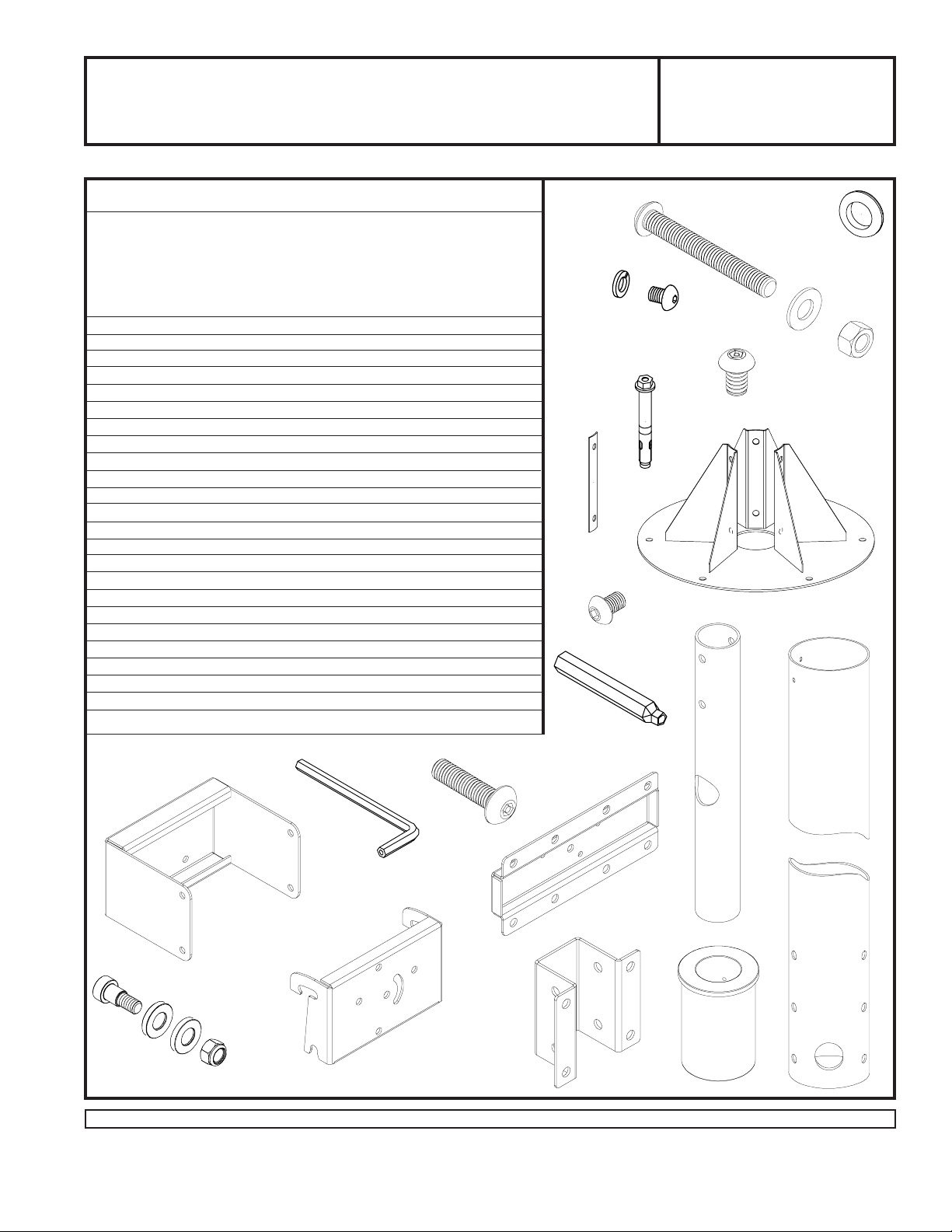
Parts List
PART # QTY. DESCRIPTION
A 200-1106 1 support column (model COL 510P only)
200-1107 (model COL 610P only)
200-1108 (model COL 710P only)
200-1109 (model COL 810P only)
B 120-0041 1 base plate
C 1390-472 3 fastener plate
D 5S1-M10-A20 6 M10-1.5 x 20 mm socket head screw
E 540-9424 6 lock washer
F 540-9407 14 flat washer
G 530-9401 2 rubber grommet
H 5M9-381-H03 6 concrete expansion anchor
I 560-9646 1 4 mm security allen wrench
J 200-1096 1 tilt bracket
K 200-1095 1 tube support
L 200-1094 1 adapter mount
M 200-1093 1 swivel bracket
N 200-1517 1 neck tube
O 590-1111 1 column bushing
P 520-9263 16 M10 x 1.5 x 15 mm penta pin screw
Q 530-9310 2 3/8 x 16 nylock nut
R 520-1015 2 3/8 x 16 x 3" socket screw bolt
T 520-1065 2 M5 x .8 x 20 mm socket pin screw
U 520-9260 1 M10 penta pin tool
V 520-9525 3 M8 x 1.25 x 12 mm socket head screw
W 530-9306 1 5/16-18 nylock nut
X 500-1082 1 5/16-18 x 3/8 shoulder bolt screw
Y 540-9454 2 3/8 x 3/4 x 1/8 flat washer
Some parts may appear slightly different than illustrated.
E
C
V
U
Models:COL 510P, COL 610P,
COL 710P, COL 810P
R
G
D
P
H
B
F
Q
A
T
I
L
N
J
X
YW
Before you start make sure all parts listed are included with your product.
Visit the Peerless Web Site at www.peerlessindustries.com For customer service call 1-800-729-0307 or 708-865-8870.
M
1 of 6
K
ISSUED: 11-24-99 SHEET #: 200-9192-2 07-23-04
O
Page 2
WARNING
• Flat panel weight is restricted to a maximum of 150 lb
(68 kg). Interfacing flat panel into electrical system at
installation site must conform to local electrical codes
governing such installations and be done by a qualified
electrician / electrical contractor.
• Installer must verify that mounting surface will safely
support the combined weight of all attached equipment
and hardware.
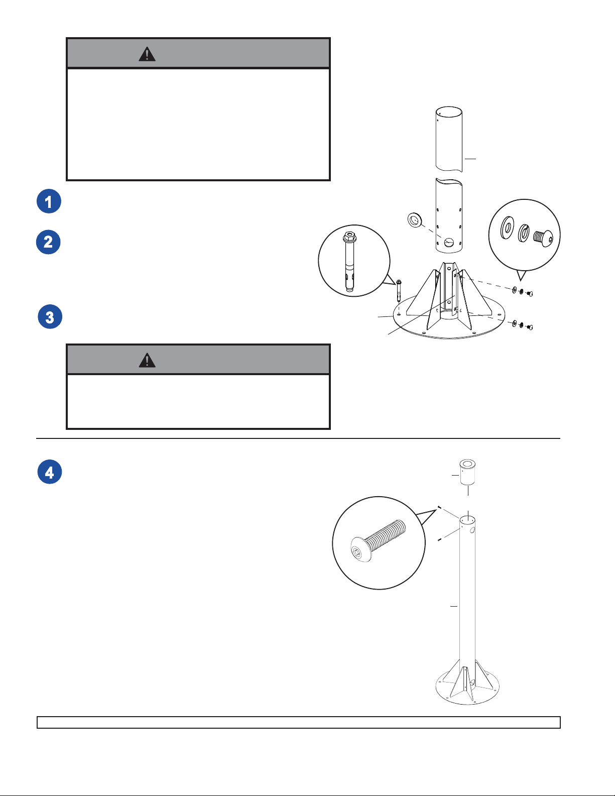
Insert rubber grommet (G) into hole in bottom of support
column (A).
At all three support legs attach support column (A) to base
plate (B) using fastener plates (C), M10-1.5 x 20 mm
socket head screws (D), lock washers (E), and flat
washers (F). Note: Leave screws slightly loose until all are
attached, then tighten all screws securely.
Attach base plate (B) to concrete floor. Use six Rawl-Bolt
concrete expansion anchors (H). Drill 3/8" dia. holes to a
minimum depth of 2".
H
B
C
G
A
F
E
D
WARNING
• For attachment to concrete floor only! All six concrete
expansion anchors must be used.
• Tighten to 420 IN • LB (47.6 N.M.) torque.
Attach column bushing (O) to support column (A) using two
screws (T). The screws control swivel action, so do not
tighten until product is fully assembled and flat panel is in
viewing position.
O
T
A
2 of 6
Visit the Peerless Web Site at www.peerlessindustries.com For customer service call 1-800-729-0307 or 708-865-8870.
ISSUED: 11-24-99 SHEET #: 200-9192-2 07-23-04
Page 3

Attach tilt bracket (J) to tube support (K)
with four screws (P) using penta pin
tool (U).
Insert four screws and washers (P & F)
into tilt bracket (J). Do not fully tighten.
Leave 1/4" of exposed thread between
tilt bracket (J) and washers (F).
K
P
J
1/4" EXPOSED
THREAD
F
P
Attach tube support (K) to neck
tube (N) using two screw bolts
(R), nuts (Q), and washers (F)
as shown. Insert rubber
grommet (G) into neck tube (N).
R
F
K
F
Q
N
G
3 of 6
Visit the Peerless Web Site at www.peerlessindustries.com For customer service call 1-800-729-0307 or 708-865-8870.
ISSUED: 11-24-99 SHEET #: 200-9192-2 07-23-04
Page 4

Attach adapter mount (L) to adapter bracket (purchased separately and may
appear different than illustrated) with eight screws (P) shown right. Attach
swivel bracket (M) to adapter mount (L) using shoulder bolt (X), washers (Y),
and nut (W) as shown below.
FOR HORIZONTAL MOUNT: secure with three screws (V) shown below left.
FOR VERTICAL MOUNT: secure with three screws (V) shown below right.
W
Y
ADAPTER
BRACKET
L
P
Y
L
M
X
SLOT
V
V
4 of 6
Visit the Peerless Web Site at www.peerlessindustries.com For customer service call 1-800-729-0307 or 708-865-8870.
ISSUED: 11-24-99 SHEET #: 200-9192-2 07-23-04
Page 5

Hook swivel bracket (M) onto tilt bracket (J). Adjust tilt
(0° to 15°) and tighten screws (P) using penta pin
tool (U).
Adjust swivel and tighten two screws (T) securing
neck tube (N).
360° SWIVEL
ADAPTER BRACKET AND FLAT
PANEL MAY APPEAR SLIGHTLY
DIFFERENT THAN ILLUSTRATED.
M
P
J
N
T
5 of 6
Visit the Peerless Web Site at www.peerlessindustries.com For customer service call 1-800-729-0307 or 708-865-8870.
ISSUED: 11-24-99 SHEET #: 200-9192-2 07-23-04
Page 6

OPTIONAL: To rotate flat panel 90° without detaching
swivel bracket (M), follow detail one through detail three.
REMOVE TWO
SCREWS (V).
LOOSEN
SCREW (V).
DETAIL 1
ROTATE MONITOR
90° AND TIGHTEN
SCREW (V).
M
DETAIL 2
DETAIL 3
INSERT AND
TIGHTEN TWO
SCREWS (V).
6 of 6
Visit the Peerless Web Site at www.peerlessindustries.com For customer service call 1-800-729-0307 or 708-865-8870.
© 2004 Peerless Industries, Inc. All rights reserved.
Peerless is a registered trademark of Peerless Industries, Inc.
All other brand and product names are trademarks or registered trademarks of their respective owners.
ISSUED: 11-24-99 SHEET #: 200-9192-2 07-23-04
 Loading...