

Installation & Assembly -
r
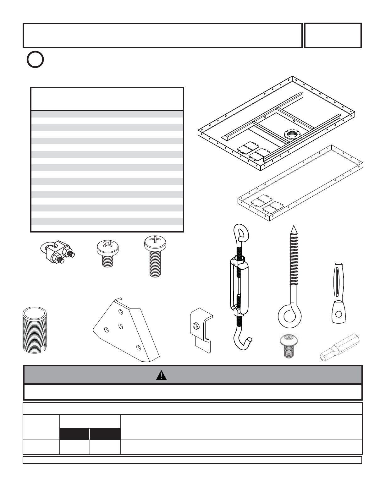
Two Piece Suspended Ceiling Plate
for Jumbo Mounts
Model: CMJ453
This product is intended for use with UL
U
©
Max. Load Capacity : 250 lb (113.4 kg)
Listed products and must be installed by a
qualifi ed professional installer.
L
USC
Parts List
Description Qty. Part #
ceiling tray
A
filler tray
A1
10 mm long phillips screw
B
20 mm long phillips screw
C
hanger bracket
D
hanger bracket clamp
E
turnbuckle
F
20' (6.1 m) tie wire (not shown)
G
safety cable (not shown)
H
safety cable clamp
J
eye bolt
K
concrete anchor 5 580-0005
L
M 1/4"-20 x 3/8" screws (not shown) 4 520-2015
N 1/4"-20 nuts (not shown) 4 530-9302
O allen wrench (not shown) 1 560-9706
P flush mount tube 1 1446-014S
Q M5 x 10 mm penta pin screw 1 505-9010
R M5 x 1" penta pin drive
1 128-2185
1 128-2207
8 520-9401
4 520-9402
4 1452-278
4 1452-279
4 560-9620
1 1450-522
1 1450-517
2 1450-518
5
1 520-9249
This Suspended Ceiling Plate is intended for use only to support Jumbo
Mount TV Brackets or other products as specifi ed by Peerless. Combine only as specifi ed (see specifi cations on page 3).
A
580-0006
A1
J
B
C
K
F
L
D
E
P
Q
R
WARNING
• Weight of TV or screen shall not exceed maximum load capacity.
TWO PIECE SUSPENDED CEILING PLATE FOR JUMBO MOUNTS - SPECIFICATIONS
Model
Number
CMJ453
Visit the Peerless Web Site at www.peerlessindustries.com For customer service call 1-800-729-0307 or 708-865-8870.
© 2005 Peerless Industries, Inc. All rights reserved.
Peerless is a registered trademark of Peerless Industries, Inc.
All other brand and product names are trademarks or registered trademarks of their respective owners.
Max. Load Capacity
Concrete
250 lb
(113.4 kg) (113.4 kg)
Wood
250 lb
Compatible Jumbo Mount Models
JM2630, JM2640, JM2640D, JM2650, JM2650D, JM2655, JM2660, JM2665, JM2670, JM2675
1 of 5
ISSUED: 5-24-99 SHEET NO: 128-9102-6 05-06-10
IMPORTANT PRE-ASSEMBLY INFORMATION:
Ceiling Trays (A), and (A1) are designed to fi t within a 24" (610 mm) x 24" (610 mm) section of a conventional sus-
pended ceiling system. Ceiling runners (see DETAIL 1, page 4) should have a "T" cross section and a minimum
height of 1.5" (38 mm). In cases where 24" (610 mm) x 48" (1219 mm) ceiling tiles are used, cut one tile in half and
add another 24" (610 mm) ceiling runner in order to make a 24" (610 mm) x 24" (610 mm) section.
For certain installations it may be best to install ceiling anchors (step 4) before installing the ceiling tray (step 3).
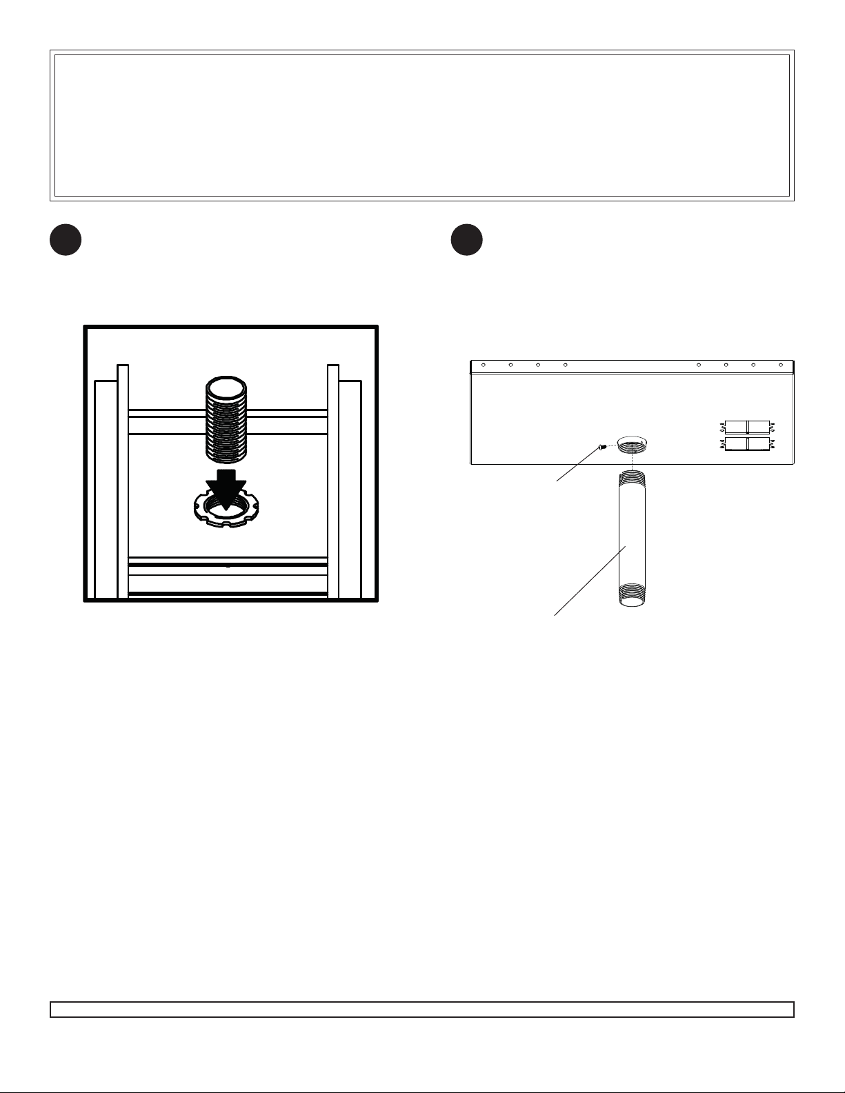
For FLUSH MOUNT TUBE Installation: From
1 2
the top, thread the Flush Mount Tube (P) through
retaining collar in Ceiling Tray (A).
Skip to step 3.
P
A
For EXTENSION COLUMN Installation: From
the bottom up, thread extension column (not
included) up through retaining collar in adjustable
collar mount plate. Align notch in extension column with hole in collar and fasten using M5 x 10
mm penta pin screw (Q) with M5 penta pin driver
(R) as shown below.
A
Q
1 1/2" EXTENSION COLUMN
(SOLD SEPARATELY)
(UL LISTED EXT OR AEC SERIES)
2 of 5
Visit the Peerless Web Site at www.peerlessindustries.com For customer service call 1-800-729-0307 or 708-865-8870.
ISSUED: 5-24-99 SHEET NO: 128-9102-6 05-06-10
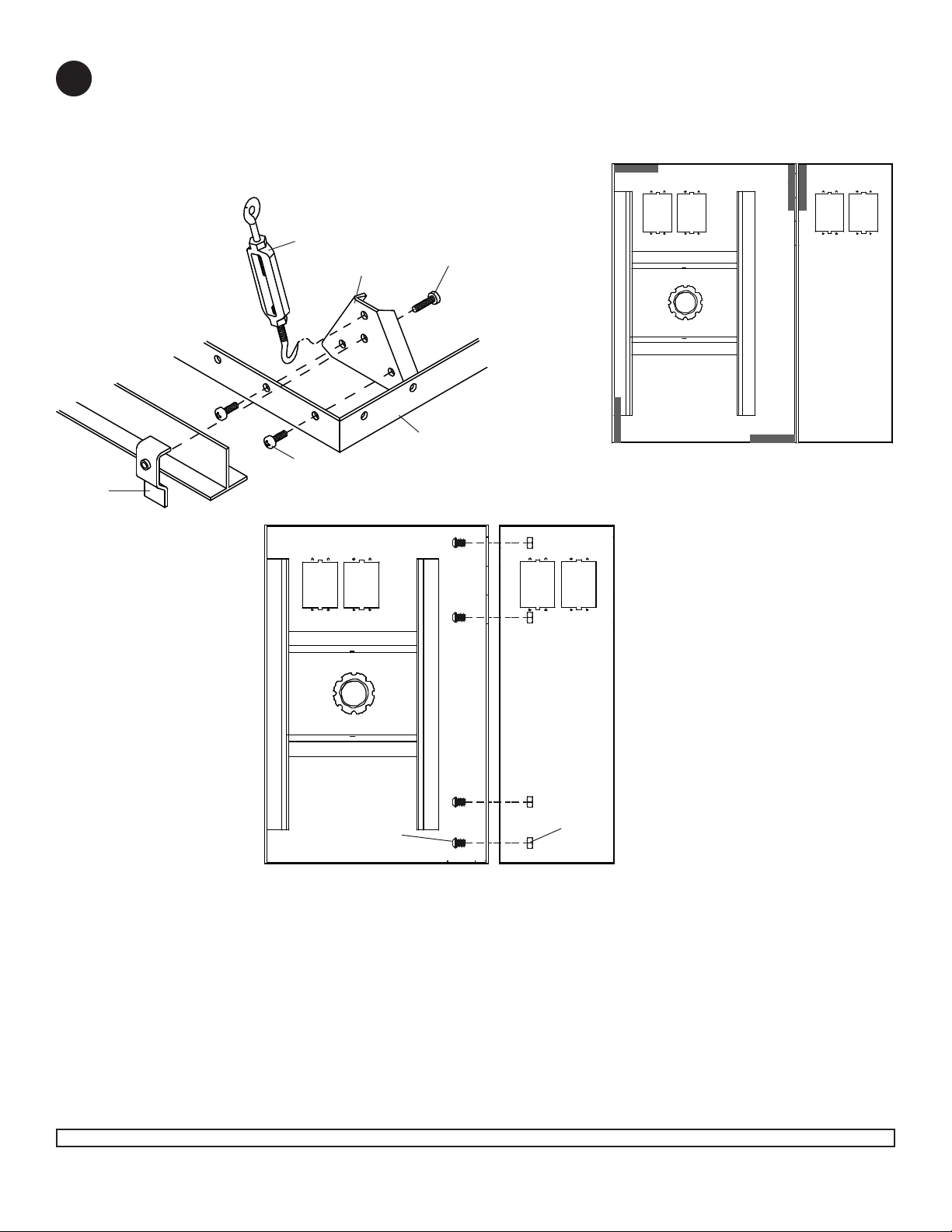
Attach four Hanger Brackets (D) to four corners of Ceiling Tray (A) using 10 mm long phillips screws (B). Place
3
Ceiling Tray (A) into 24" (610 mm) x 24" (610 mm) opening in ceiling (in place of a ceiling tile) with retaining collar
to center, right, or left. Place Filler Tray (A1) into gap. Attach Ceiling Tray (A) to Filler Tray (A1) using four bolts
(M) and nuts (N). Clamp Ceiling Tray (A) to Ceiling Runners using Hanger Bracket Clamps (E) and 20mm long
phillips screws (C). Hook Turnbuckles (F) into Hanger Brackets (D). Hook one Turnbuckle through (A1) and (A)
where indicated by black rectangle.
Ceiling Runner
E
B
F
D
C
AA1
A
TOP VIEW - CEILING TRAY
Black rectangles show correct
positions for Hanger brackets.
M
3 of 5
Visit the Peerless Web Site at www.peerlessindustries.com For customer service call 1-800-729-0307 or 708-865-8870.
N
ISSUED: 5-24-99 SHEET NO: 128-9102-6 05-06-10

Cut tie wire (G) into four pieces of equal length. Insert wires through ends of turnbuckles. Twist each wire around
4
itself at least four times.
Drill holes for four ceiling anchors (see "Various Anchoring Methods"). Position the holes so that when the tie
wires (G) are attached and taut will angle out at 15
retaining collar in ceiling tray.
Pull tie wires tight and attach to ends of ceiling anchors (or truss). Again twist each wire around itself at least four
times.
When this step is complete, the weight of the ceiling tray should be supported by the tie wires.
Note: 20' (6.1 m) of tie wire (G) is provided. If space between the true ceiling and suspended ceiling is more than
36" (914 mm), additional wire (12 gauge annealed, steel, black) will be needed. Longer safety cable (H) may also
be needed.
VARIOUS ANCHORING METHODS
O
. Drill a fi fth anchor hole directly above the center of the
Wood Joists or Beams
Drill 5/32" (4 mm) dia
holes 2" (51 mm) deep.
Fully insert eye bolts (K).
Solid Concrete
Drill 1/4" (6 mm) dia. holes 1.5" (38 mm)
deep. Hammer in Concrete Anchor (L) using
Rawl #3250 setting tool or equivalent.
K
WARNING
• Installer must verify that the ceiling will safely
support four times the combined weight of all
attached equipment and hardware.
• Never attach hooks to fi ller tray.
L
Truss Ceiling
No anchor required. After attaching tie wire to turnbuckle
loop upper end around ceiling
truss. Pull tie wire tight and
twist it around itself at least
four times.
GG G G
H
A
Run the safety cable (H) through the remaining
5
ceiling anchor. Pass each end through holes in
ceiling plate reinforcements and join with cable
clamp (J). DO NOT TIGHTEN YET!
Suspended Ceiling Kit installation is now complete. After all components (Jumbo Mount, Extension Column, etc.) and equipment (monitor,
VCR, etc.) have been attached, tension the tie
wires by adjusting turnbuckles (F). Load must
be carried by tie wires - not suspended ceiling runners. Finally, take up the slack in safety
cable (H) leaving it slightly loose. Tighten both
safety cable clamps (J).
Visit the Peerless Web Site at www.peerlessindustries.com For customer service call 1-800-729-0307 or 708-865-8870.
DETAIL 1
Ceiling Runner
Knockout panels are provided for electrical outlet boxes
and antenna leads.
H
J
DETAIL 2
Safety Cable and
Cable Clamp.
4 of 5
All other brand and product names are trademarks or registered trademarks of their respective owners.
ISSUED: 5-24-99 SHEET NO: 128-9102-6 05-06-10
© 2008, Peerless Industries, Inc. All rights reserved.

LIMITED FIVE-YEAR WARRANTY
Peerless Industries, Inc. establishes a warranty period of fi ve years for products manufactured or supplied by Peerless. This period commences from the date of
sale of the product to the original consumer, but will in no case last for more than six years after the date of the product’s manufacture. During the warranty period
such products will be free from defects in material and workmanship, provided they are installed and used in compliance with the instructions established by
Peerless Industries, Inc. Subject to applicable legal requirements, during the warranty period Peerless will repair or replace, or refund the purchase price of, any
Any other warranties prescribed by the law which may apply with respect to such products also are limited in duration to the warranty period specifi ed in this
This warranty does not cover damage caused by (a) service or repairs by the customer or a person who is not authorized for such service or repairs by Peerless
Industries, Inc., (b) the failure to utilize proper packing when returning the product, (c) incorrect installation or the failure to follow Peerless’ instructions or warnings
when installing, using or storing the product, or (d) misuse or accident, in transit or otherwise, including in cases of third party actions and force majeure.
In no event shall Peerless be liable for incidental or consequential damages or damages arising from the theft of any product, whether or not secured by a security
This Limited Five-Year Warranty is in lieu of all other warranties, expressed or implied, and is the sole remedy with respect to product defects. No retailer, dealer,
distributor, installer or other person is authorized to modify or extend this warranty or impose any obligation on Peerless in connection with the sale of any product
This warranty gives specifi c legal rights, and you may also have other rights provided by the national legislation of the country in which you purchased such
such product which fails to conform with this warranty.
Limited Five-Year Warranty.
device which may be included with the product.
manufactured or supplied by Peerless.
product.
www.peerlessmounts.com
© 2008 Peerless Industries, Inc.
5 of 5
Visit the Peerless Web Site at www.peerlessindustries.com For customer service call 1-800-729-0307 or 708-865-8870.
ISSUED: 5-24-99 SHEET NO: 128-9102-6 05-06-10
 Loading...