

Page 1
Installation and Assembly:
A
CC-EXC
A
CC-EXC-S
A
CC-EXC-
W
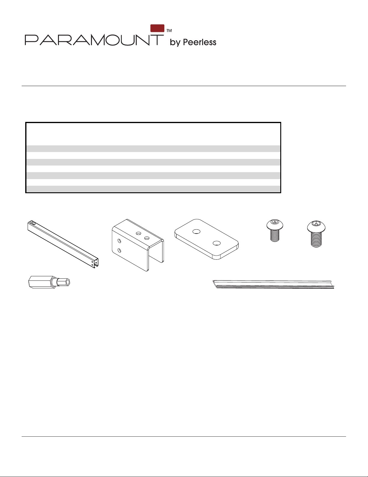
Description Qty Part # Part # Part #
A
inner channel 1 055-1769 055-4769 055-2769
B extension clamp 1 120-1181 120-4181 120-2181
C cable cover 1
055-1809 055-4809 055-2809
D nut plate 2
120-1182 120-4182 120-2182
E
M6 x 12 mm socket pin screw
2 520-1050 520-2050 520-2050
F M5 x 10 mm socket pin screw 4 520-2063 520-2063 520-2063
G 4 mm security driver 1
560-1133 560-1133 560-1133
Parts List
Paramount™ Projector Ceiling Mount
Models: ACC-EXC, ACC-EXC-S, ACC-EXC-W
WARNING: Not to be used in wall applications.
Before you begin, make sure all parts shown are included with your product.
A
G
Parts may appear slightly different than illustrated.
B
D EF
C
Visit the Peerless Web Site at www.peerlessmounts.com
1 of 2
ISSUED: 06-19-08 SHEET #: 056-9006-1
For customer care call 1-800-865-2112 or 708-865-8870.
Page 2
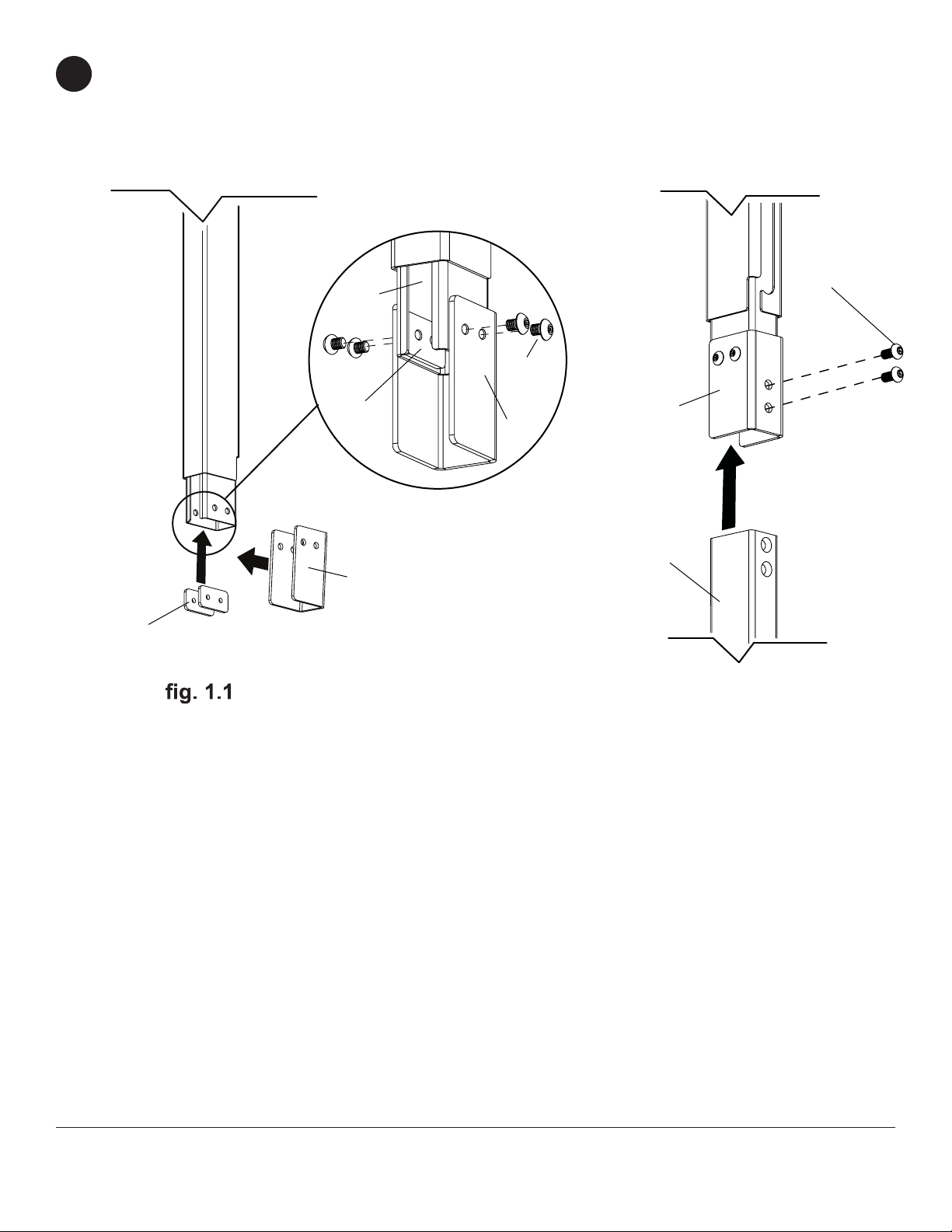
Position two nut plates (D) on each side of inner channel (A) as seen in g. 1.1. detail 1. Slide extension clamp (B)
1
over bottom of inner channel (A), line up holes from nut plate and secure using four M5 x 10 mm screws (F).
Slide second inner channel (A) into extension clamp (B) as seen in g. 1.2. and secure using four M5 x 12 mm
screws (E) as shown in gure 1.2.
D
A
D
DETAIL 1
B
E
F
B
E
A
g. 1.2
Visit the Peerless Web Site at www.peerlessmounts.com
2 of 2
ISSUED: 06-19-08 SHEET #: 056-9006-1
For customer care call 1-800-865-2112 or 708-865-8870.
 Loading...