

Page 1
Installation and Assembly:
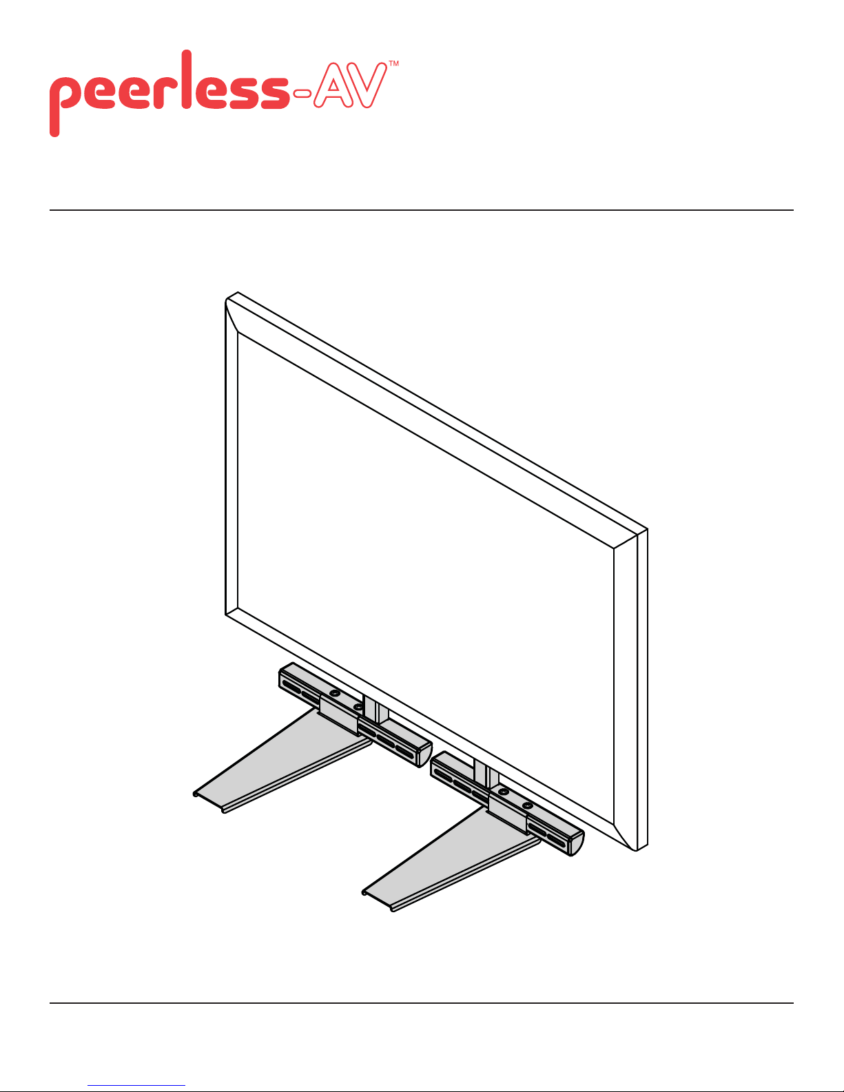
Accessory Shelf for Small Pivot and Articulating Mounts
Model: ACC955
2300 White Oak Circle • Aurora, Il 60502 • (800) 865-2112 • Fax: (800) 359-6500 • www.peerlessmounts.com
Max Load Capacity: 15 lb (6.8 kg)
ISSUED: 09-26-11 SHEET #: 120-9124-3 03-02-12
Page 2
NOTE: Read entire instruction sheet before you start installation and assembly.
WARNING
• Do not begin to install your Peerless product until you have read and understood the instructions and warnings
contained in this Installation Sheet. If you have any questions regarding any of the instructions or warnings, for US
customers please call Peerless customer care at 1-800-865-2112, for all international customers, please contact
your local distributor.
• This product should only be installed by someone of good mechanical aptitude, has experience with basic building
construction, and fully understands these instructions.
• Make sure that the supporting surface will safely support the combined load of the equipment and all attached
hardware and components.
• Never exceed the Maximum Load Capacity. See page one.
• Always use an assistant or mechanical lifting equipment to safely lift and position equipment.
• Tighten screws fi rmly, but do not overtighten. Overtightening can damage the items, greatly reducing their holding
power.
• This product is intended for indoor use only. Use of this product outdoors could lead to product failure and personal
injury.
Tools Needed for Assembly
• phillips screwdriver
• level
• utiltiy knife
• adjustable wrench
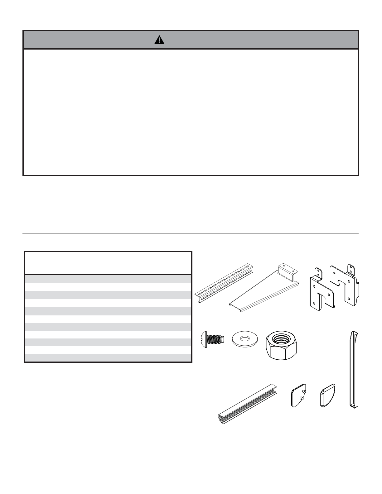
Before you begin, make sure all parts shown are included with your product.
Parts List
Description Qty.
A horizontal bracket 2 125-P1259
B shelf 2 125-P1279
C left mount bracket 1 125-P1262
D right mount bracket 1 125-P1260
E M5 x 16mm self tapping screw 10 520-9515
F washer 14 540-9400
G
nut 4 530-1019
H cover 2 125-1274
I left cap 2 125-1276
J right cap 2 125-1275
K adjustment bracket 2 125-P1261
Parts may appear slightly different than illustrated.
Part #
E F
A
B
G
C
IH J
D
K
2 of 14
ISSUED: 09-26-11 SHEET #: 120-9124-3 03-02-12
Page 3
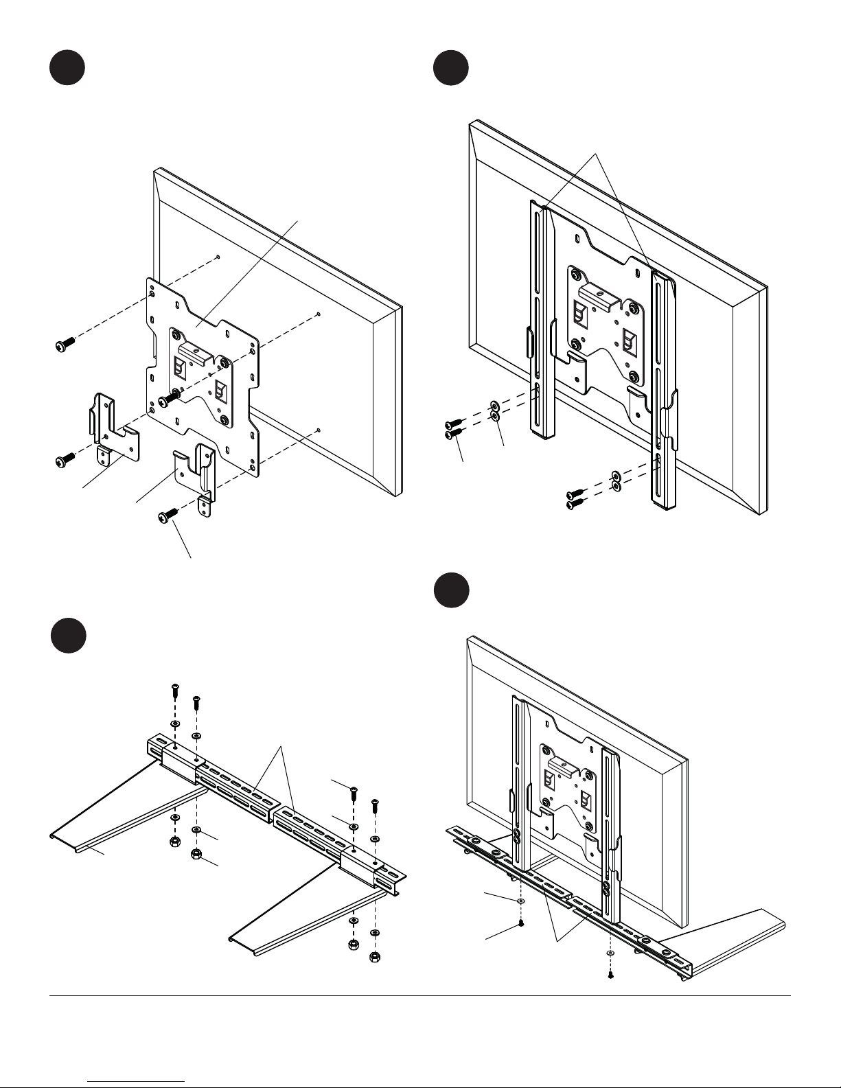
Display must be removed from display mount prior
to installing speaker mount. Attach mount brackets
1
(C, D) to display mount using M4, M5 or M6 screws
provided with your display mount.
NOTE: M8 screws cannot be used with this
accessory. NOTE: See your display mount
instructions for details.
DISPLAY MOUNT
Attach adjustment brackets (K) to mount brackets
(C, D) using four screws (E) and four washers (F).
2
NOTE: Do not fully tighten screws (E) until step 5.
K
C
D
M4, M5, M6 SCREWS
Attach shelves (B) to horizontal brackets (A) using
four screws (E), eight washers (F) and four
3
nuts (G).
A
E
F
F
B
G
F
E
Attach horizontal brackets (A) to adjustment
brackets (K) using two screws (E) and two
4
washers (F).
3 of 14
F
E
A
ISSUED: 09-26-11 SHEET #: 120-9124-3 03-02-12
Page 4
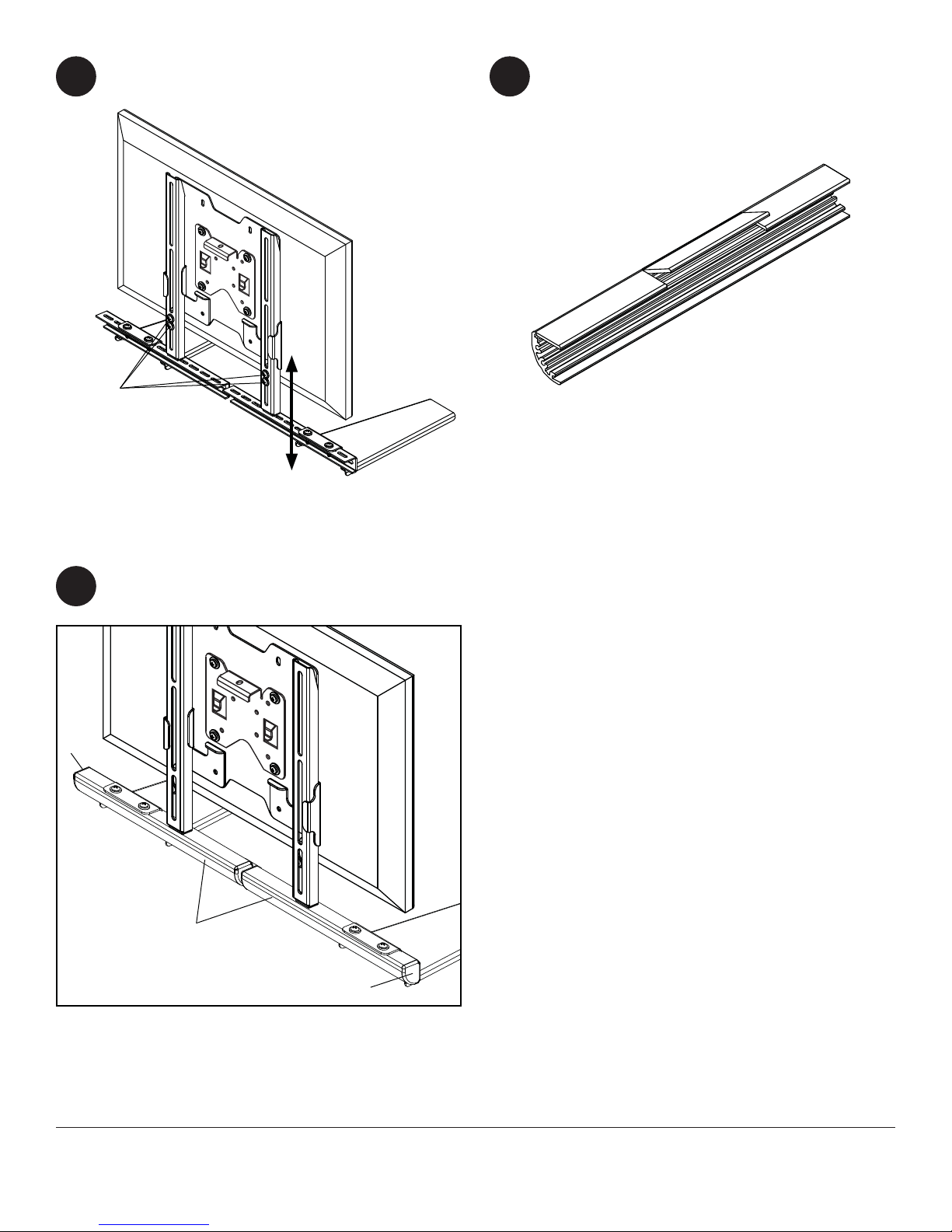
Adjust accessory shelf to desired height then
tighten four screws (E).
5
E
Use a utility knife to cut covers (H) to fi t around
6
adjustment brackets (K) and shelves (B) on
horizontal brackets (A). NOTE: In order to break
the caps apart you may have to bend covers (H)
on the cut marks.
H
Attach covers (H) to horizontal brackets (A). Attach
left cap (I) and right cap (J) to horizontal
7
brackets (A).
I
H
J
4 of 14
All other brand and product names are trademarks or registered trademarks of their respective owners.
ISSUED: 09-26-11 SHEET #: 120-9124-3 03-02-12
© 2012, Peerless Industries, Inc. All rights reserved.
Page 5

Instalación y montaje:
Estante para accesorios
Pivote de la Pequeña y articulación de Montes
Modelos: ACC955
2300 White Oak Circle • Aurora, Il 60502 • (800) 865-2112 • Fax: (800) 359-6500 • www.peerlessmounts.com
Capacidad Máxima de Soportar Carga: 15 lb (6.8 kg)
PUBLICADO: 09-26-11 HOJA #: 120-9124-3 03-02-12
Page 6

Español
NOTA: Lea la hoja de instrucciones completa antes de comenzar la instalación y el ensamblaje.
ADVERTENCIA
• No comience a instalar su producto de Peerless hasta haber leído y entendido las instrucciones y las advertencias
contenidas en la Hoja de Instalación. Si tiene alguna pregunta acerca de cualquiera de las instrucciones o las
advertencias, por favor, llame a Servicio al Cliente de Peerless al 1-800-865-2112 si está en EE. UU. Si es un cliente
internacional, por favor, comuníquese con su distribuidor local.
• Este producto sólo debe ser instalado por una persona que tenga una buena aptitud mecánica, que tenga
experiencia en construcción básica de edifi cios y que entienda estas instrucciones en su totalidad.
• Asegúrese de que la superfi cie de apoyo sostendrá, con seguridad, la carga combinada del equipo y todos los
fi jadores y componentes.
• Nunca sobrepase la capacidad máxima de soportar carga.
• Siempre cuente con la ayuda de un asistente o utilice un equipo mecánico de izar para levantar y colocar el equipo
con más seguridad.
• Apriete los tornillos con fi rmeza, pero no en exceso. Apretarlos en exceso puede dañar los artículos y puede
disminuir signifi cativamente su fuerza de fi jación.
• Este producto está diseñado para uso en interiores solamente. Utilizar este producto en exteriores podría causar
fallas del producto y lesiones a individuos.
Herramientas necesarias para el ensamblaje
• destornillador phillips
• nivel
• cuchillo
• llave ajustable
Vea la página 5.
Antes de comenzar, asegúrese de que su producto incluye todas las piezas ilustradas.
Lista de piezas
o
N.
Descripción Cant.
A soporte horizontal 2 125-P1259
B estante 2 125-P1279
C izquierda soporte de montaje 1 125-P1262
D derecho soporte de montaje 1 125-P1260
E tornillo autorroscante M5 x 16mm 10 520-9515
F arandela 14 540-9400
G
tuerca 4 530-1019
H tapa 2 125-1274
I tapa de la izquierda 2 125-1276
J tapa de la derecha 2 125-1275
K adjustment bracket 2 125-P1261
Algunas partes pueden diferir un poco de las ilustradas.
de pieza
E F
A
B
G
C
IH J
D
K
6 de 14
PUBLICADO: 09-26-11 HOJA #: 120-9124-3 03-02-12
Page 7

La pantalla debe ser retirado de la pantalla de
montaje antes de instalar los altavoces de montaje.
1
Fije soportes de montaje (C, D) para mostrar
montaje utilizando los tornillos M4, M5 o M6
incluidos con el soporte para pantalla. NOTA: M8
tornillos no se puede utilizar con este accesorio.
NOTA: Consulte las instrucciones de montaje de
pantalla para obtener más detalles.
PANTALLA DE MONTAJE
Fije los soportes de ajuste (K) para montaje en
bastidor (C, D) con cuatro tornillos (E) y cuatro
2
arandelas (F). NOTA: No apriete los tornillos (E)
hasta el paso 5.
K
Español
C
D
TORNILLOS M4, M5, M6
Adjuntar los estantes (B) a los soportes de
horizontal (A) con cuarto tornillos (E), ocho
3
arandelas (F) y cuarto tuerca (G).
A
F
B
G
E
F
F
E
Adjuntar los soportes horizontales (A) a los
soportes de ajuste (K) con dos tornillos (E) y dos
4
arandelas (F).
7 de 14
F
E
A
PUBLICADO: 09-26-11 HOJA #: 120-9124-3 03-02-12
Page 8

Ajuste estante para accesorios a la altura deseada
y apretado los cuatro tornillos (E).
5
E
Utilizar un cuchillo para cortar las tapas (H) para
encajar alrededor de los soportes de ajuste (K) y
6
las estantes (B) en los soportes horizontales (A).
NOTA: En el fi n de romper las tapas aparte es
posible que tenga que doblar las tapas (H) en las
marcas de corte.
H
Español
Coloque las tapas (H) a los soportes horizontales
(A). Adjuntar tapa a la izquierda (I) y la tapa
7
derecha (J) en los soportes horizontales (A).
I
H
J
8 de 14
Cualesquiera otras marcas y nombres de productos son marcas comerciales o registradas de sus respectivos dueños.
PUBLICADO: 09-26-11 HOJA #: 120-9124-3 03-02-12
© 2012, Peerless Industries, Inc. Todos los derechos reservados.
Page 9

Installation et assemblage:
Accessoires rack pivot pour les petits et les monts articuler
Modèles: ACC955
2300 White Oak Circle • Aurora, Il 60502 • (800) 865-2112 • Fax: (800) 359-6500 • www.peerlessmounts.com
Capacité de Charge Maximum: 15 lb (6.8 kg)
PUBLIÉ LE: 09-26-11 FEUILLE no: 120-9124-3 03-02-12
Page 10

Français
REMARQUE: lisez entièrement la fi che d’instructions avant de commencer l’installation et l’assemblage.
AVERTISSEMENT
• Ne commencez pas à installer votre produit Peerless avant d’avoir lu et assimilé les instructions et les avertissements
contenus dans cette fi che d’installation. Pour toute question concernant les instructions ou les avertissements,
veuillez appeler le service à la clientèle de Peerless au 1-800-865-2112; tous les clients internationaux sont priés de
contacter leur distributeur local.
• Ce produit doit être installé uniquement par quelqu’un possédant une bonne aptitude à la mécanique, une expérience
de la construction immobilière et ayant bien compris ces instructions.
• Assurez-vous que la surface de support puisse soutenir sans danger la charge totale de l’équipement ainsi que des
pièces et composants qui y sont attachés.
• Ne dépassez jamais la capacité de charge maximum. Reportez-vous à la page 9.
• Pour lever et positionner l’équipement en toute sécurité, faites-vous toujours aider par une autre personne ou utilisez
un dispositif de levage mécanique.
• Serrez fermement les vis, mais sans excès. Un serrage excessif peut endommager les composants et en réduire
considérablement la capacité de support.
• Ce produit est conçu uniquement pour un usage intérieur. L’utilisation de ce produit à l’extérieur peut causer une
défaillance du produit et des blessures corporelles.
Outils nécessaires au montage
• tournevis phillips
• niveau
• couteau
• clé à écrous
Avant de commencer, veillez à ce que toutes les pièces énumérées soient incluses.
Liste des pièces
Description Qté
A support horizontale 2 125-P1259
B étagères 2 125-P1279
C gauche support de montage 1 125-P1262
D droite support de montage 1 125-P1260
E vis autotaraudeuse M5 x 16mm 10 520-9515
F rondelle 14 540-9400
G
écrou 4 530-1019
H couvercle 2 125-1274
I couvercle gauche 2 125-1276
J couvercle right 2 125-1275
K support de réglage 2 125-P1261
Il est possible que les pièces semblent légèrement
différentes de celles illustrées ici.
Référence
des pièces
E F
A
B
G
C
IH J
D
K
10 sur 14
PUBLIÉ LE: 09-26-11 FEUILLE no: 120-9124-3 03-02-12
Page 11

L'écran doit être retiré de l'écran de montage
avant d'installer le mont haut-parleur. Montez
1
parenthèses (C, D) pour affi cher monter en utilisant
les vis M4, M5 ou M6 fournies avec votre monture
d'affi chage. REMARQUE: Vis M8 ne peut pas
être utilisé avec cet accessoire. REMARQUE: Voir
vos instructions de montage d'affi chage pour les
détails.
AFFICHAGE DE MONTAGE
Fixer les supports de réglage (K) pour montage
en rack (C, D) à l'aide de quatre vis (E) et quatre
2
rondelles (F). REMARQUE: Ne serrez pas
complètement les vis (E) jusqu'à l'étape 5.
K
Français
C
D
VIS M4, M5, M6
Fixer étagères (B) à crochets de horizontal (A) à
l'aide de quatre vis (E), huit rondelles (F) et quatre
3
écrou (G).
A
E
F
F
B
G
F
E
Fixer les supports horizontaux (A) pour supports
de réglage (K) à l'aide de deux vis (E) et deux
4
rondelles (F).
11 sur 14
F
E
A
PUBLIÉ LE: 09-26-11 FEUILLE no: 120-9124-3 03-02-12
Page 12

Ajustez le Accessoires rack à la hauteur désirée,
puis serrés quatre vis (E).
5
E
Utiliser un couteau pour couper couvercle (H)
pour s'adapter autour de supports de réglage (K)
6
et des étagères (B) sur des supports horizontaux
(A). NOTE: Afi n de briser les couvercle à part que
vous pourriez avoir à se plier couvercle (H) sur les
marques de coupe.
H
Français
Fixez couvercle (H) à des supports horizontaux
(A). Attacher tapa gauche (I) et le tapa droit (J) sur
7
des supports horizontaux (A).
I
H
J
12 sur 14
Tous les autres noms de marques et de produits sont des marques de commerce ou déposées de leurs propriétaires respectifs.
PUBLIÉ LE: 09-26-11 FEUILLE no: 120-9124-3 03-02-12
© 2012, Peerless Industries, Inc. Tous droits réservés.
Page 13

LIMITED FIVE-YEAR WARRANTY
Peerless Industries, Inc. (“Peerless”) warrants to original end-users of Peerless® products will be free from defects in material and workmanship, under normal
use, for a period of fi ve years from the date of purchase by the original end-user (but in no case longer than six years after the date of the product’s manufacture).
In no event shall the duration of any implied warranty of merchantability or fi tness for a particular purpose be longer than the period of the applicable
express warranty set forth above. Some states do not allow limitations on how long an implied warranty lasts, so the above limitation may not apply to you.
This warranty does not cover damage caused by (a) service or repairs by the customer or a person who is not authorized for such service or repairs by Peerless,
(b) the failure to utilize proper packing when returning the product, (c) incorrect installation or the failure to follow Peerless’ instructions or warnings when installing,
In no event shall Peerless be liable for incidental or consequential damages or damages arising from the theft of any product, whether or not secured
by a security device which may be included with the Peerless® product. Some states do not allow the exclusion or limitation of incidental or consequential
This warranty is in lieu of all other warranties, expressed or implied, and is the sole remedy with respect to product defects. No dealer, distributor, installer or other
person is authorized to modify or extend this Limited Warranty or impose any obligation on Peerless in connection with the sale of any Peerless® product.
At its option, Peerless will repair or replace, or refund the purchase price of, any product which fails to conform with this warranty.
using or storing the product, or (d) misuse or accident, in transit or otherwise, including in cases of third party actions and force majeure.
damages, so the above limitation or exclusion may not apply to you.
This warranty gives specifi c legal rights, and you may also have other rights which vary from state to state.
www.peerlessmounts.com
© 2012 Peerless Industries, Inc.
Español
GARANTÍA LIMITADA DE CINCO AÑOS
Peerless Industries, Inc. (Peerless) les garantiza a los usuarios fi nales originales de los productos Peerless® que los productos Peerless® estarán libres de
defectos de materiales o de manufactura, en condiciones de uso normal, durante un periodo de cinco (5) años a partir de la fecha en la que el usuario fi nal
original compre cualquier producto (pero, en ningún caso, durante un periodo mayor de 6 años después de la fecha de manufactura del producto). Queda a la
La duración de toda garantía implícita de comerciabilidad o de idoneidad para un propósito en particular no sobrepasará en caso alguno el periodo
de vigencia de la garantía explícita correspondiente indica en lo anterior. Algunos Estados no permiten que se establezcan limitaciones en relación con el
Esta garantía no cubre daños causados por (a) trabajos de mantenimiento o de reparación hechos por el cliente o alguna persona que no esté autorizada por
Peerless para realizar dichos trabajos de mantenimiento o de reparación, (b) no empacar el producto como es debido si lo devuelve, (c) hacer una instalación
incorrecta o no seguir las instrucciones o las advertencias de Peerless al instalar, utilizar o guardar el producto o (d) el mal uso o los accidentes, en tránsito o en
Peerless no tendrá responsabilidad en ningún caso de daños y perjuicios incidentales o indirectos o de daños y perjuicios que surjan por el robo de
cualquier producto, ya sea que el mismo esté o no esté asegurado con un dispositivo de seguridad que se haya incluido con el producto de Peerless®.
Algunos Estados no permiten que se excluyan o se establezcan limitaciones en relación con los daños y perjuicios incidentales o indirectos, de manera que es
Esta garantía remplaza toda otra garantía, expresa o implícita, y es el único recurso en lo que respecta a los defectos del producto. Ningún concesionario,
distribuidor, instalador ni ninguna otra persona está autorizada a modifi car o extender esta Garantía Limitada ni a imponer obligación alguna a Peerless en
Esta garantía concede derechos específi cos creados por ley y es posible que usted, además, tenga otros derechos que varían de acuerdo con el Estado donde
discreción de Peerless, reparar, reemplazar o rembolsar el precio de compra de cualquier producto que no cumpla esta garantía.
periodo de duración de una garantía implícita, de manera que es posible que la limitación expuesta en lo anterior no sea pertinente a usted.
otras circunstancias, incluidos los casos relacionados con las acciones de terceros o una fuerza mayor.
posible que la limitación o la exclusión expuesta en lo anterior no sea pertinente a usted.
relación con la venta de cualquier producto de Peerless®.
se encuentre.
www.peerlessmounts.com
13 of 14
© 2012 Peerless Industries, Inc.
ISSUED: 09-26-11 SHEET #: 120-9124-3 03-02-12
Page 14

Français
GARANTIE DE CINQ ANS
Peerless Industries, Inc. (« Peerless ») garantit aux utilisateurs fi naux d’origine des produits PeerlessMD que lesdits produits ne présenteront aucun défaut de
matériau ou de main-d’œuvre, dans la mesure où ils sont utilisés normalement, pendant une période de cinq ans à compter de la date d’achat par l’utilisateur fi nal
d’origine (mais en aucun cas plus de six ans après la date de fabrication du produit). Peerless, à sa discrétion, réparera ou remplacera tout produit non conforme
La durée de toute garantie implicite de qualité commerciale ou d'application à un usage particulier n'excédera en aucun cas la durée de la garantie
applicable expressément stipulée plus haut. Certains états ou provinces n’autorisent pas la limitation de la durée d’une garantie implicite, et la limitation ci-
Cette garantie ne couvre pas les dommages causés par (a) un entretien ou des réparations effectués par l'acheteur ou une personne non autorisée par Peerless
à effectuer un tel entretien ou de telles réparations, (b) un emballage inadéquat lors de l’expédition d’un produit retourné, (c) une installation incorrecte ou le non-
respect des instructions ou mises en garde de Peerless lors de l'installation, l'utilisation ou le rangement du produit, ou (d) une mauvaise utilisation ou un accident
Peerless ne peut en aucun cas être tenu responsable de quelque dommage accessoire ou indirect que ce soit ni de dommages résultant du vol d’un
quelconque produit, que celui-ci ait été ou non protégé par un dispositif de sécurité intégré à un produit PeerlessMD. Certains états ou provinces
n’autorisent pas l'exclusion ou la restriction des dommages accessoires ou indirects, et il est possible que les restrictions ou exclusions ci-dessus ne s'appliquent
Les dispositions de cette garantie remplacent toute autre garantie expresse ou implicite et constituent le seul recours possible en cas de défectuosité d’un
produit. Aucun marchand, distributeur, installateur ou autre personne n’est autorisé à modifi er ou étendre la portée de cette garantie limitée, ni à imposer quelque
Cette garantie offre des droits juridiques particuliers auxquels peuvent s’ajouter d’autres droits, susceptibles de varier d’une province ou d’un état à l’autre.
survenu lors d’un transport ou autrement, y compris l'intervention de tiers et les cas de force majeure.
obligation ce que soit à Peerless en ce qui concerne la vente de tout produit PeerlessMD.
aux termes de cette garantie, ou en remboursera le prix d’achat.
dessus peut donc ne pas vous être applicable.
pas à votre cas.
www.peerlessmounts.com
© 2012 Peerless Industries, Inc.
14 of 14
ISSUED: 09-26-11 SHEET #: 120-9124-3 03-02-12
 Loading...