

Page 1
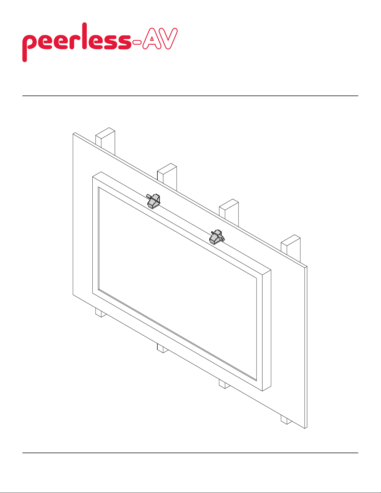
Installation and Assembly:
Above Display Security Lock Accessory
Models: ACC952
2300 White Oak Circle • Aurora, Il 60502 • (800) 865-2112 • Fax: (800) 359-6500 • www.peerlessmounts.com
ISSUED: 04-05-11 SHEET #: 120-9105-1
Page 2

Note: Read entire instruction sheet before you start installation and assembly.
WARNING
• Do not begin to install your Peerless product until you have read and understood the instructions and warnings
contained in this Installation Sheet. If you have any questions regarding any of the instructions or warnings, for US
customers please call Peerless customer care at 1-800-865-2112, for all international customers, please contact
your local distributor.
• This product should only be installed by someone of good mechanical aptitude, has experience with basic building
construction, and fully understands these instructions.
• If mounting to wood wall studs, make sure that mounting screws are anchored into the center of the studs. Use of
an "edge to edge" stud fi nder is highly recommended.
• Tighten screws fi rmly, but do not overtighten. Overtightening can damage the items, greatly reducing their holding
power.
• This product is intended for indoor use only. Use of this product outdoors could lead to product failure and personal
injury.
• This product was designed to be installed on the following wall construction only;
WALL CONSTRUCTION HARDWARE REQUIRED
• Wood Stud Included
• Wood Beam Included
• Solid Concrete Included
• Cinder Block Included
• Brick Contact Qualifi ed Professional
• Other or unsure? Contact Qualifi ed Professional
Tools Needed for Assembly
• stud fi nder ("edge to edge" stud fi nder is recommended)
• drill
• 1/4" (6mm) bits for concrete and cinder block wall
• level
Table of Contents
Parts List.................................................................................................................................................................................3
Installation to Wood Stud Wall ................................................................................................................................................4
Installation to Solid Concrete or Cinder Block ........................................................................................................................5
2 of 20
ISSUED: 04-05-11 SHEET #: 120-9105-1
Page 3
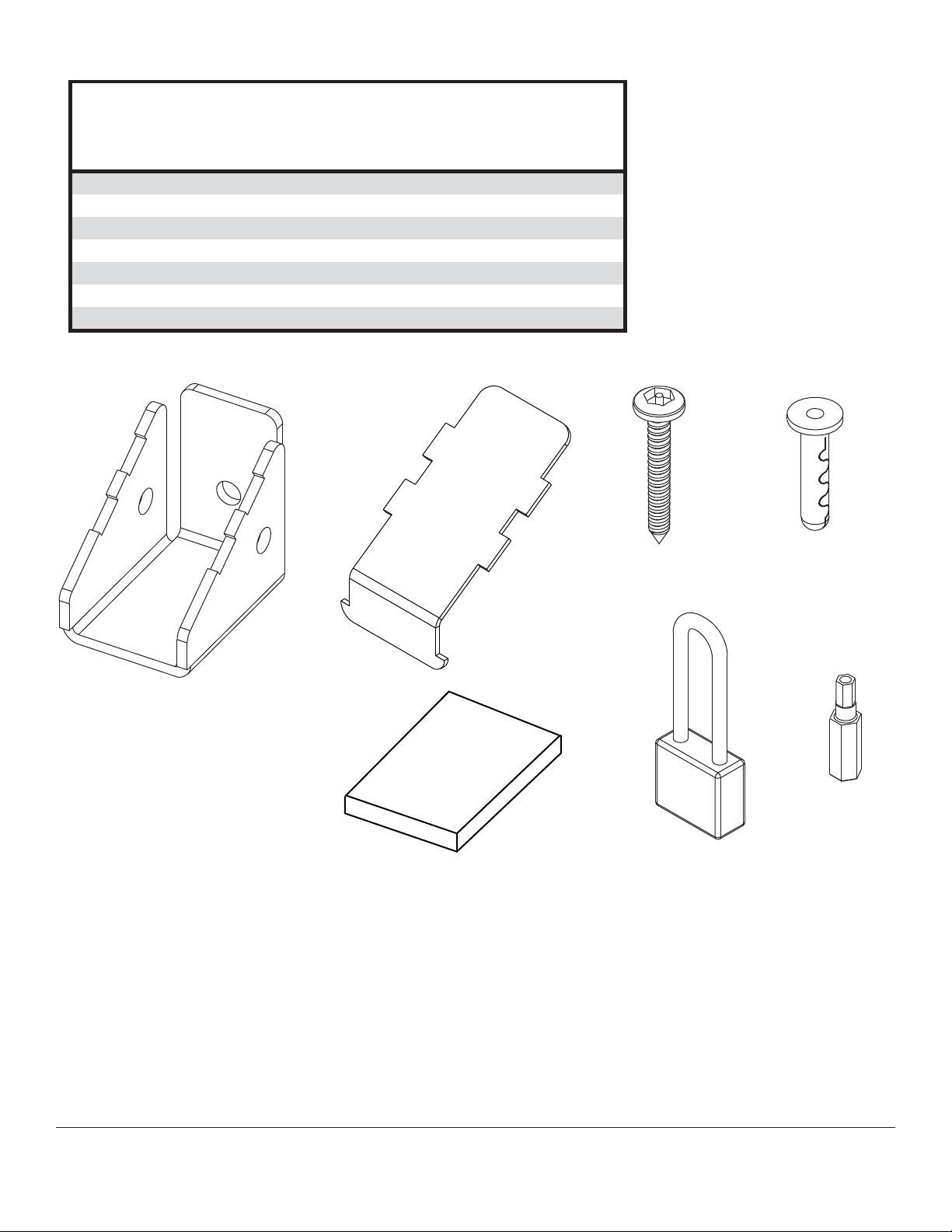
Before you begin, make sure all parts shown are included with your product.
Parts List
Description Qty. Part #
A
wall bracket 2 046-P1227
B
cover bracket 2 046-P1226
C
wood screw 2 520-1092
D
concrete anchor 2 590-0097
E
foam pad 2 570-0050
F
padlock 2 600-0217
G
4mm security driver 1 560-1133
Parts may appear slightly different than illustrated.
AB
C
D
E
3 of 20
F
G
ISSUED: 04-05-11 SHEET #: 120-9105-1
Page 4
Installation to Wood Stud Wall
WARNING
• Tighten wood screws so that wall bracket is fi rmly attached, but do not overtighten. Overtightening can damage the
screws, greatly reducing their holding power.
• Never tighten in excess of 80 in. • lb (9 N.M.).
• Make sure that mounting screws are anchored into the center of the stud. The use of an "edge to edge" stud fi nder
is highly recommended.
• Hardware provided is for attachment of mount through standard thickness drywall or plaster into wood studs.
Installers are responsible to provide hardware for other types of mounting situations.
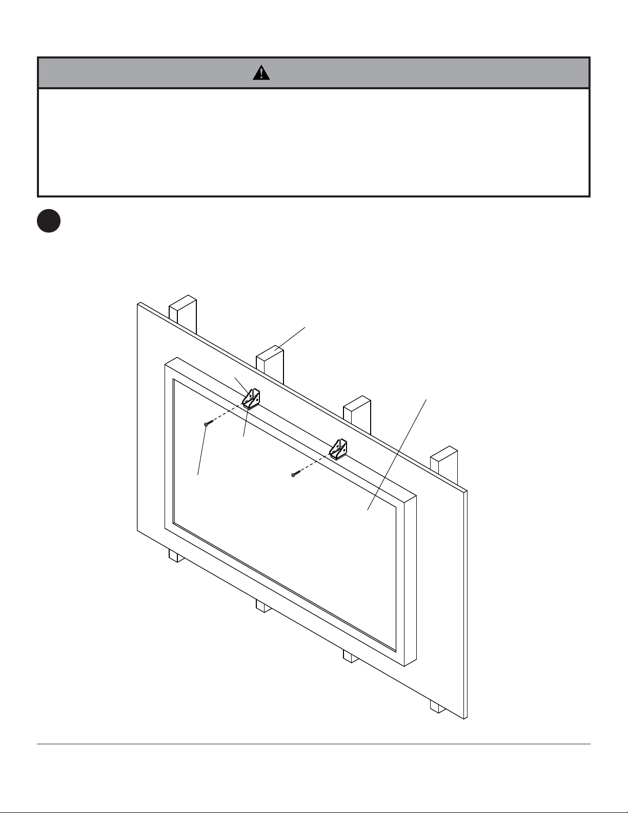
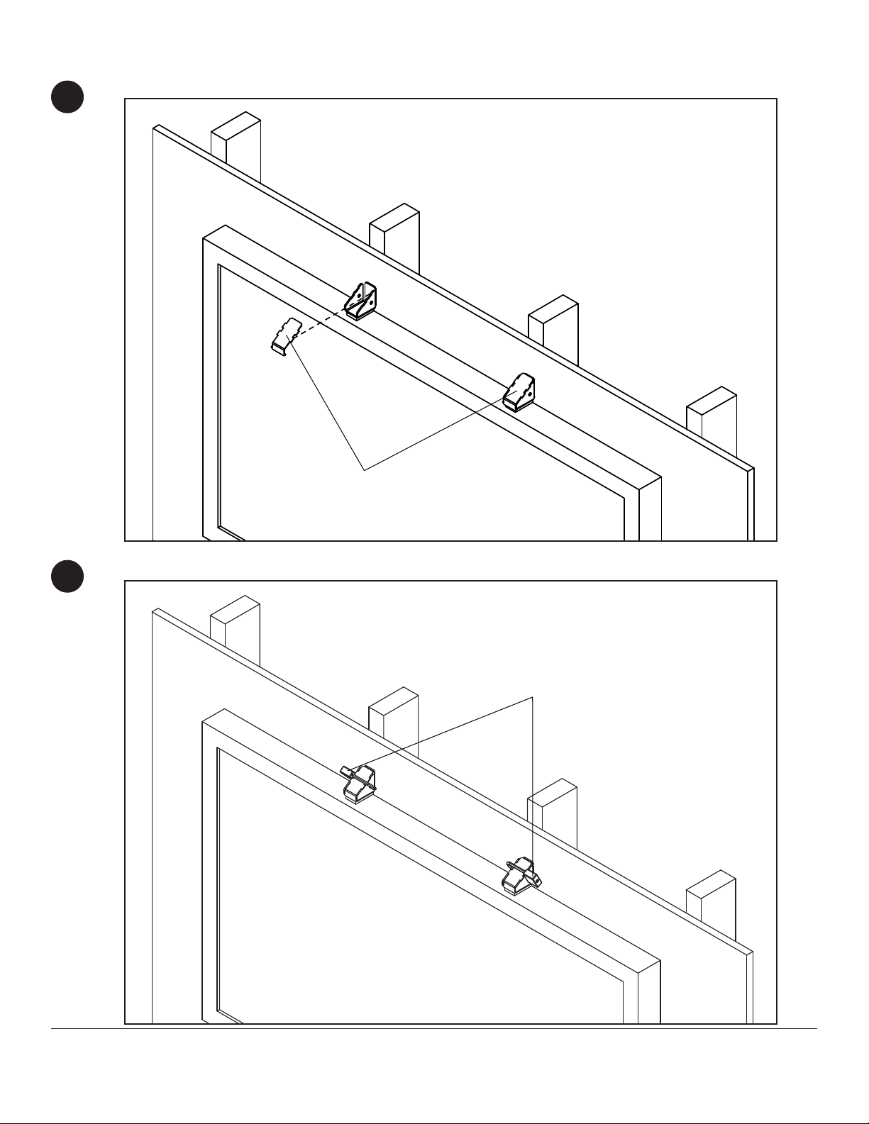
Apply foam pad (E) to bottom of wall bracket (A).
1
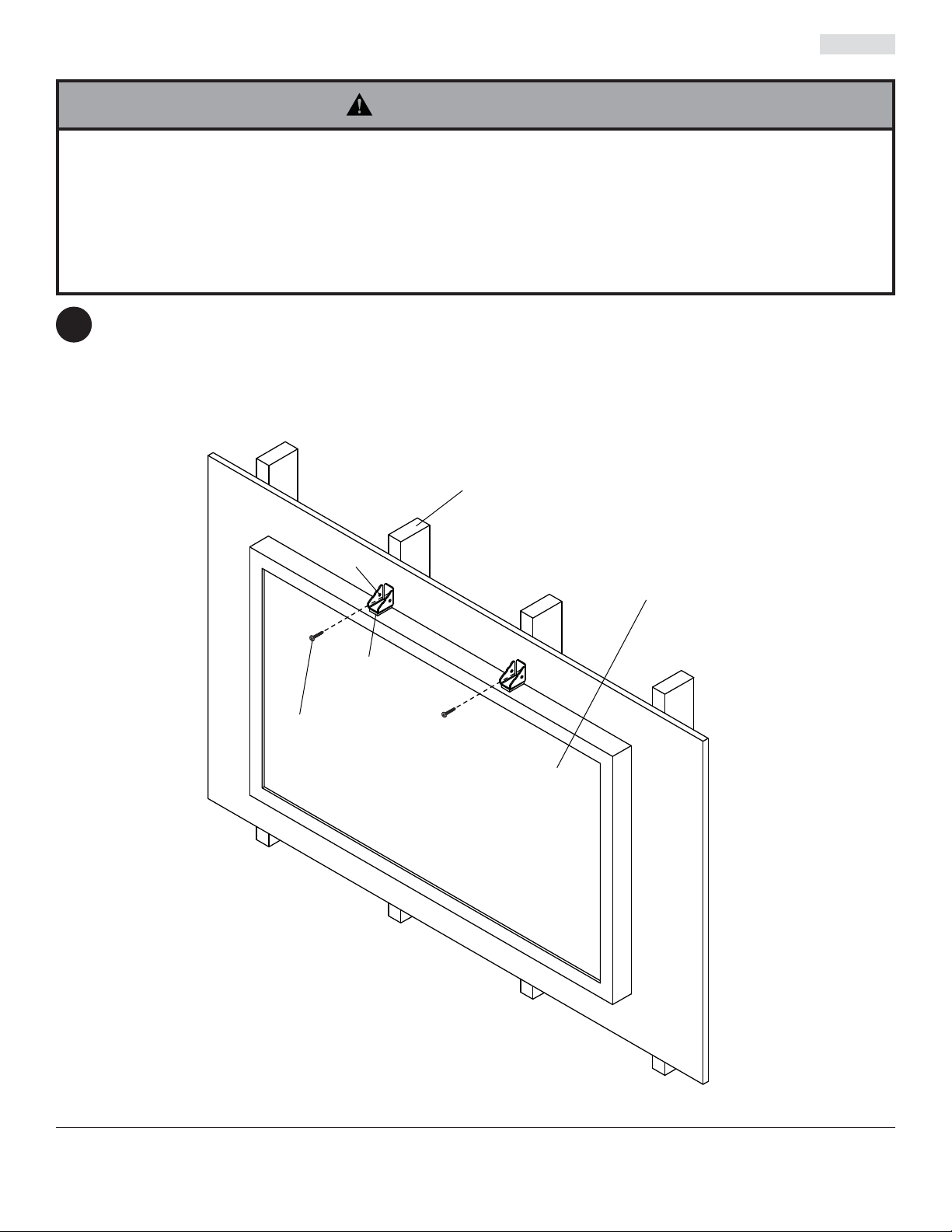
Use a stud fi nder to locate the edges of the stud. Use of an edge-to-edge stud fi nder is highly recommended.
Based on their edges, draw a vertical line down each stud’s center. Place wall bracket (A) on wall as a template,
resting on top of display. Secure wall bracket (A) to wall with security wood screw (C).
WOOD STUD
C
A
DISPLAY
E
4 of 20
ISSUED: 04-05-11 SHEET #: 120-9105-1
Page 5
Installation to Solid Concrete or Cinder Block
WARNING
• When installing Peerless wall mounts on cinder block, verify that you have a minimum of 1-3/8" (35 mm) of actual
concrete thickness in the hole to be used for the concrete anchors. Do not drill into mortar joints! Be sure to mount
in a solid part of the block, generally 1" (25 mm) minimum from the side of the block. Cinder block must meet ASTM
C-90 specifi cations. It is suggested that a standard electric drill on slow setting is used to drill the hole instead of a
hammer drill to avoid breaking out the back of the hole when entering a void or cavity.
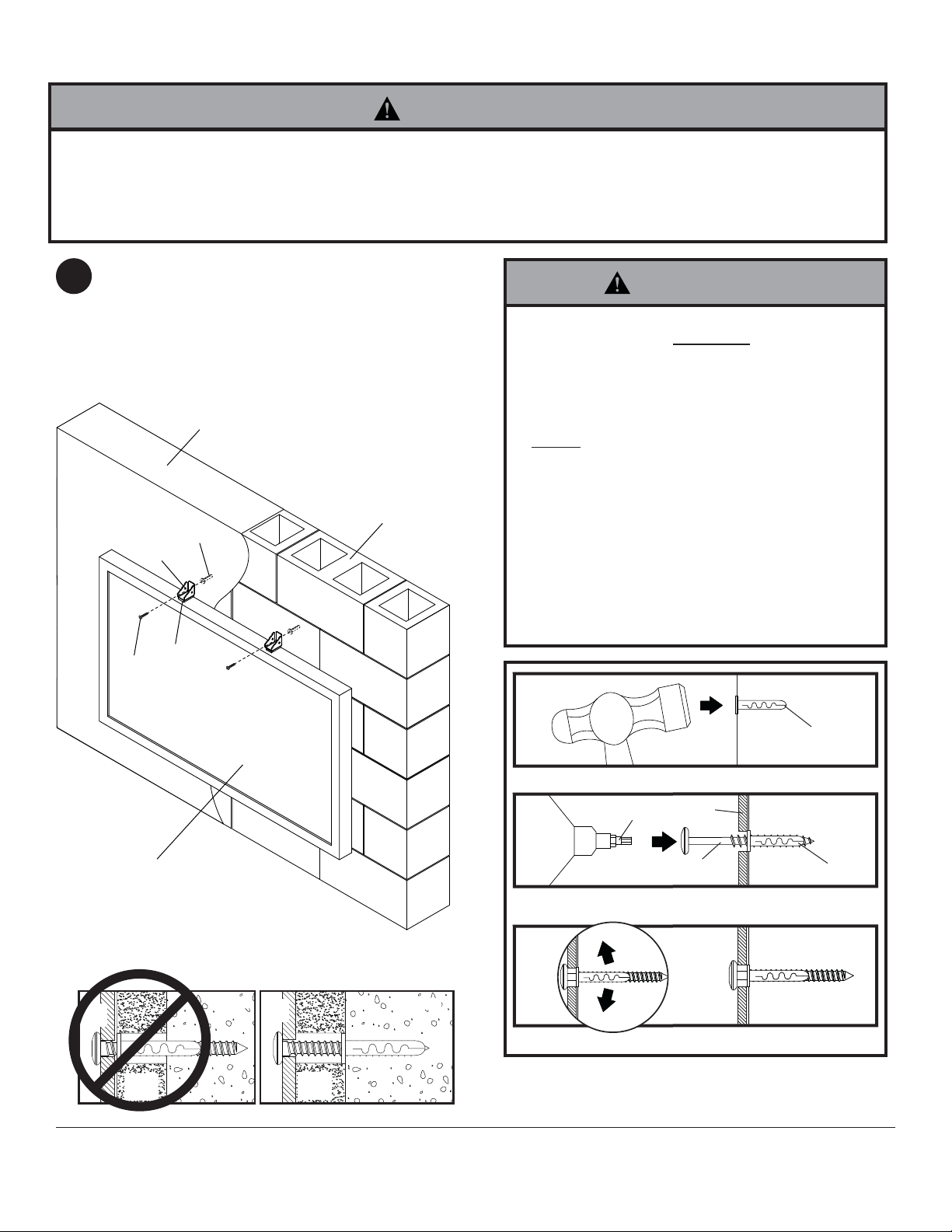
Apply foam pad (E) to bottom of wall bracket (A).
1
Place wall bracket (A) on wall, resting on top of
display, and mark the center of mounting hole. Drill
a 1/4" (6mm) dia. hole to a minimum depth of 2".
Insert alligator anchor (D) into hole. Secure wall
bracket (A) to wall with security wood screw (C).
solid concrete
cinder block
D
A
• Tighten screws so that wall plate is fi rmly
attached, but do not overtighten. Overtightening
can damage screws, greatly reducing their
holding power.
• Never tighten in excess of 80 in. • lb (9 N.M.).
• Always attach concrete expansion anchors
directly to load-bearing concrete.
• Never attach concrete expansion anchors
to concrete covered with plaster, drywall, or
other fi nishing material. If mounting to concrete
surfaces covered with a fi nishing surface is
unavoidable, the fi nishing surface must be
counterbored as shown below. Be sure concrete
anchors do not pull away from concrete when
tightening screws. If plaster/drywall is thicker
than 5/8" (16 mm), custom fasteners must be
supplied by installer.
WARNING
plate
CUTAWAY VIEW
wall
C
display
plaster/
dry wall
E
INCORRECT CORRECT
concrete
wall
plate
plaster/
dry wall
concrete
1
concrete
surface
D
Drill holes and insert anchors (D).
C
A
D
2
Place plate (A) over anchors (D) and secure with screws (C).
G
3
Tighten all fasteners.
5 of 20
ISSUED: 04-05-11 SHEET #: 120-9105-1
Page 6
Place cover bracket (B) onto wall bracket (A).
2
DETAIL 1
B
Lock in place using padlock (F).
3
DETAIL 2
F
6 of 20
ISSUED: 04-05-11 SHEET #: 120-9105-1
Page 7

Instalación y montaje:
Above Display Security Lock Accessory
Modelos: ACC952
2300 White Oak Circle • Aurora, Il 60502 • (800) 865-2112 • Fax: (800) 359-6500 • www.peerlessmounts.com
PUBLICADO: 04-05-11 HOJA #: 120-9105-1
Page 8

Español
NOTA: Lea la hoja de instrucciones completa antes de comenzar la instalación y el ensamblaje.
ADVERTENCIA
• No comience a instalar su producto de Peerless hasta haber leído y entendido las instrucciones y las advertencias
contenidas en la Hoja de Instalación. Si tiene alguna pregunta acerca de cualquiera de las instrucciones o las advertencias, por favor, llame a Servicio al Cliente de Peerless al 1-800-865-2112 si está en EE. UU. Si es un cliente
internacional, por favor, comuníquese con su distribuidor local.
• Este producto sólo debe ser instalado por una persona que tenga una buena aptitud mecánica, que tenga experiencia en construcción básica de edifi cios y que entienda estas instrucciones en su totalidad.
• Si va a instalar el producto en una pared con montantes de madera, asegúrese de que los tornillos de montaje estén
anclados en el centro de los montantes. Se recomienda utilizar un localizador de montantes de "borde a borde".
• Apriete los tornillos con fi rmeza, pero no en exceso. Apretarlos en exceso puede dañar los artículos y puede disminu-
ir signifi cativamente su fuerza de fi jación.
• Este producto está diseñado para uso en interiores solamente. Utilizar este producto en exteriores podría causar fallas del producto y lesiones a individuos.
• Este producto fue diseñado para ser instalado en paredes con la siguiente construcción solamente:
CONSTRUCCIÓN DE LA PARED ACCESORIOS NECESARIOS
• Montante de madera Incluido
• Viga de madera Incluido
• Concreto macizo Incluido
• Bloque de hormigón de escorias Incluido
• Ladrillo Comuníquese con un profesional califi cado
• ¿Otra superfi cie o no está seguro? Comuníquese con un profesional califi cado
Herramientas necesarias para el ensamblaje
• localizador de montantes (se recomienda uno de "borde a borde")
• taladro
• broca de 1/4" (6 mm) para paredes de concreto y de bloque de hormigón de escorias
• nivel
Contenido
Lista de piezas........................................................................................................................................................................9
Instalación en una pared con montantes de madera .......................................................................................................... 10
Instalación en una pared de concreto macizo o de bloques de hormigón de escorias ........................................................11
8 de 20
PUBLICADO: 04-05-11 HOJA #: 120-9105-1
Page 9

Antes de comenzar, asegúrese de que su producto incluye todas las piezas ilustradas.
Lista de piezas
Descripción Cant. N.o de pieza
A
soporte de pared 2 046-P1227
B
cubierta del soporte 2 046-P1226
C
tornillo para madera 2 520-1092
D
anclaje para concreto 2 590-0097
E
almohadilla de espuma 2 570-0050
F
candado 2 600-0217
G
destornillador de seguridad de 4 mm 1 560-1133
Algunas partes pueden diferir un poco de las ilustradas.
AB
C
Español
D
E
9 de 20
F
G
PUBLICADO: 04-05-11 HOJA #: 120-9105-1
Page 10
Español
Instalación en una pared con montantes de madera
ADVERTENCIA
• Apriete los tornillos para madera de tal modo que la placa de apoyo quede fi rmemente sujeta, pero no apriete en
exceso. El apriete excesivo puede dañar los tornillos, reduciendo enormemente su fuerza de fi jación.
• Nunca apriete más de 80 pulg-lb (9 N•m).
• Asegúrese de que los tornillos de montaje queden bien fi jos en el centro del montante. Se recomienda usar un local-
izador de montantes de "borde a borde".
• Los herrajes suministrados son para fi jar el soporte a través de tabique de yeso-cartón o yeso de espesor estándar a
los montantes de madera. Los instaladores son responsables de suministrar los herrajes para otros tipos de situaciones de montaje.
Aplicar almohadilla de espuma (E) a la parte inferior del soporte de pared (A).
1
Utilice un localizador de montantes para localizar los bordes de los montantes. Se recomienda utilizar un
localizador de montantes de "borde a borde". Tomando los bordes como punto de referencia, trace una línea
vertical por el centro de cada montante. Coloque la placa de pared (A) contra la pared para utilizarla como
plantilla. Resto en la parte superior de la desplay. Asegurar el soporte de pared (A) a la pared con la seguridad de
madera tornillo (C).
MONTANTE
C
A
PANTALLA
E
10 de 20
PUBLICADO: 04-05-11 HOJA #: 120-9105-1
Page 11

Instalación en una pared de concreto macizo o de
Español
bloques de hormigón de escorias
ADVERTENCIA
• Cuando instale soportes de pared Peerless en bloques de hormigón de escorias, verifi que que tengan un mínimo de
1-3/8" (35 mm) de superfi cie efectiva de concreto en el agujero que va a utilizar para los anclajes de concreto. ¡No
perfore en las juntas de mortero! Asegúrese de instalar el soporte en una parte sólida del bloque, generalmente a un
mínimo de 1" (25 mm) del costado del bloque. El bloque de hormigón de escorias debe ser de conformidad con las
especifi caciones C-90 de ASTM. Se sugiere taladrar el agujero con un taladro eléctrico normal en velocidad lenta en
vez de un taladro percutor para evitar romper la parte trasera del agujero al entrar en un espacio o cavidad.
Aplicar almohadilla de espuma (E) a la parte inferior
1
del soporte de pared (A). Coloque el soporte
de pared (A) en la pared, descansando en la
parte superior de la pantalla, y marcar el centro
del agujero de montaje. Perforar un agujero de
diámetro de 1/4" (6 mm) a una profundidad mínima
de 2". Inserte los anclajes (D) en los agujeros a ras
con la pared. Asegurar el soporte de pared (A) a la
pared con la seguridad de madera tornillo (C).
concreto macizo
bloque de hormigón
de escorias
D
A
• Apriete los tornillos de tal modo que la placa de apoyo
quede fi rmemente sujeta, pero no los apriete en
exceso. El apriete excesivo puede dañar los tornillos,
reduciendo enormemente su fuerza de fi jación.
• Nunca apriete más de 80 pulg-lb (9 N•m).
• Siempre fi je los anclajes de expansión directamente
al concreto que soporta carga.
• Nunca fi je los anclajes de expansión a una pared
de concreto recubierta con yeso, tabiques de yesocartón u otro material de acabado. Si el montaje a
superfi cies de concreto recubiertas con una superfi cie
de acabado es inevitable, será necesario escariar el
acabado, como se muestra más abajo. Asegúrese de
que los anclajes de concreto no se alejen del concreto
al apretar los tornillos. Si el grosor de la pared de
yeso/tabique de yeso-cartón es mayor que 5/8", el
instalador deberá suministrar fi jaciones especiales.
ADVERTENCIA
PANTALLA
placa
de
pared
VISTA EN CORTE
C
E
INCORRECTO CORRECTO
concreto
yeso / tabique de yeso-cartón
placa
pared
de
concreto
11 de 20
1
Perfore los agujeros y después inserte los anclajes (D).
2
G
A
superfi cie de
concreto
C
Coloque la placa (A) sobre los anclajes (D) y fíjela con
los tornillos (C).
3
Apriete todas las fi jaciones.
PUBLICADO: 04-05-11 HOJA #: 120-9105-1
D
D
Page 12

Coloque la cubierta del soporte (B) en el soporte de pared (A).
2
DETALLE 1
Español
Bloqueo en su lugar con candado (F).
3
B
DETALLE 2
F
12 de 20
PUBLICADO: 04-05-11 HOJA #: 120-9105-1
Page 13

Installation et assemblage:
Above Display Security Lock Accessory
Modèles: ACC952
2300 White Oak Circle • Aurora, Il 60502 • (800) 865-2112 • Fax: (800) 359-6500 • www.peerlessmounts.com
PUBLIÉ LE: 04-05-11 FEUILLE no: 120-9105-1
Page 14

Français
REMARQUE: lisez entièrement la fi che d’instructions avant de commencer l’installation et l’assemblage.
AVERTISSEMENT
• Ne commencez pas à installer votre produit Peerless avant d’avoir lu et assimilé les instructions et les avertissements contenus dans cette fi che d’installation. Pour toute question concernant les instructions ou les avertissements,
veuillez appeler le service à la clientèle de Peerless au 1-800-865-2112; tous les clients internationaux sont priés de
contacter leur distributeur local.
• Ce produit doit être installé uniquement par quelqu’un possédant une bonne aptitude à la mécanique, une expérience
de la construction immobilière et ayant bien compris ces instructions.
• Lors d’une installation sur un mur à montants en bois, assurez-vous que les vis de montage sont ancrées au centre
des montants. L’utilisation d’un localisateur de montants « bord à bord » est fortement recommandée.
• Serrez fermement les vis, mais sans excès. Un serrage excessif peut endommager les composants et en réduire
considérablement la capacité de support.
• Ce produit est conçu uniquement pour un usage intérieur. L’utilisation de ce produit à l’extérieur peut causer une défaillance du produit et des blessures corporelles.
• Ce produit a été conçu uniquement pour une installation sur les types de murs ci-dessous :
TYPE DE MUR PIÈCES DE FIXATION REQUISES
• Montant en bois Incluses
• Poutre en bois Incluses
• Béton plein Incluses
• Bloc de béton de mâchefer Incluses
• Brique Contacter un professionnel qualifi é
• Autre, ou vous n’êtes pas sûr ? Contacter un professionnel qualifi é
Outils nécessaires au montage
• localisateur de montants (un localisateur de montants « bord à bord » est recommandé)
• perceuse
• foret de 1/4 po (6 mm) pour les murs à block de béton
• niveau
Tabla de contenido
Lista de piezas......................................................................................................................................................................15
Installation sur un mur à montants en bois ...........................................................................................................................16
Installation sur du béton plein ou un bloc de béton de mâchefer .........................................................................................17
14 sur 20
PUBLIÉ LE: 04-05-11 FEUILLE no: 120-9105-1
Page 15

Avant de commencer, veillez à ce que toutes les pièces énumérées soient incluses..
Français
Liste des pièces
Description Qté.
A
support mural 2 046-P1227
B
couvercle support 2 046-P1226
C
vis à bois 2 520-1092
D
chevilles d'ancrage pur béton 2 590-0097
E
coussin en mousse 2 570-0050
F
cadenas 2 600-0217
G
embout de sécurité de 4 mm 1 560-1133
Il est possible que les pièces semblent légèrement différentes de celles illustrées ici.
Référence
des pièces
AB
C
D
E
15 sur 20
F
G
PUBLIÉ LE: 04-05-11 FEUILLE no: 120-9105-1
Page 16

Français
Installation sur un mur à montants en bois
AVERTISSEMENT
• Serrez les vis à bois de manière que la plaque murale soit fermement fi xée, mais sans excès. Un serrage excessif
peut endommager les vis et en réduire considérablement le pouvoir de maintien.
• Ne serrez jamais à plus de 9 Nm (80 po-lb).
• Assurez-vous que les vis de montage sont ancrées au centre des montants. L’usage d’un localisateur de montants
« bord à bord » est fortement conseillé.
• La visserie est fournie pour fi xer la monture à travers une cloison sèche ou du plâtre d’épaisseur standard et
dans des montants en bois. Il appartient aux installateurs de fournir la visserie nécessaire pour d’autres types de
situations.
Appliquer coussin en mousse (E) au fond du support mural (A).
1
Utilisez un localisateur de montants pour repérer les bords des montants. L’usage d’un localisateur bord à bord
est fortement conseillé. En fonction de leurs bords, tracez une ligne verticale le long du centre de chaque montant.
Utilisez la plaque murale (A) comme gabarit et placez-la sur le mur. Elle reposer sur le dessus de l'desplay.
Sécuriser le support mural (A) au mur à la sécurité vis à bois (C).
MONTANT
C
A
ÉCRAN
E
16 sur 20
PUBLIÉ LE: 04-05-11 FEUILLE no: 120-9105-1
Page 17

Français
Installation sur du béton plein ou un bloc de béton de mâchefer
AVERTISSEMENT
• Si vous installez des montures murales Peerless sur un bloc de béton de mâchefer, vérifi ez que vous disposez d’une
épaisseur de béton d’au moins 3,4 cm (1 3/8 po) dans le trou destiné aux ancrages de béton. Ne percez pas dans
les joints de mortier ! Veillez à effectuer le montage dans une partie pleine du bloc, généralement à au moins 2,5 cm
(1 po) du côté du bloc. Le bloc de béton de mâchefer doit être conforme aux spécifi cations de l’ASTM C-90. Pour
percer le trou, il est conseillé d’utiliser une perceuse électrique standard sur un réglage bas au lieu d’un marteau
perforateur, afi n d’éviter de briser la partie arrière du trou lorsque vous pénétrez un vide ou une cavité.
Appliquer coussin en mousse (E) au fond du
1
support mural (A). Placez le support mural (A) sur
le mur, se reposant sur le dessus de l'écran, et
marquer le centre du trou de montage. Percez un
trou de diamètre 1/4 po (6mm) à une profondeur
minimale de 2 po. Insérez les chevilles d’ancrage
(D) dans les trous au ras du mur. Sécuriser le
support mural (A) au mur à la sécurité vis à bois
(C).
béton plein
bloc de béton
de mâchefer
D
A
• Serrez les vis de manière que la plaque murale
soit fermement fi xée, mais sans excès. Un serrage
excessif peut endommager les vis et en réduire
considérablement le pouvoir de maintien.
• Ne serrez jamais à plus de 9 Nm (80 po-lb).
• Fixez toujours des ancrages de béton directement sur
du béton porteur.
• Ne fi xez jamais d’ancrages sur du béton recouvert de
plâtre, une cloison sèche ou autre matériau de fi nition.
Si vous ne pouvez pas éviter d’effectuer le montage
sur du béton recouvert d’une surface de fi nition,
celle-ci doit être chambrée, comme indiqué cidessous.
Assurez-vous que les ancrages de béton ne se
séparent pas du béton lorsque vous serrez les vis. Si
l’épaisseur du plâtre / de la cloison sèche dépasse
1,5 cm (5/8 po), des fi xations adaptées devront être
fournies par l’installateur.
AVERTISSEMENT
C
ÉCRAN
plaque
mural
plâtre /
VUE EN COUPE
cloison sèche
E
INCORRECT CORRECT
béton
plaque
mural
plâtre /
cloison sèche
béton
1
Percez des trous et insérez les ancrages (D).
2
G
A
C
Placez la plaque (A) sur les ancrages (D) et fi xez avec
des vis (C).
3
Serrez toutes les fi xations.
surface en
béton
D
D
17 sur 20
PUBLIÉ LE: 04-05-11 FEUILLE no: 120-9105-1
Page 18

Placez le couvercle support (B) sur le support mural (A).
2
Français
DÉTAILLÉ 1
Verrouiller en place en utilisant un cadenas (F).
3
B
DÉTAILLÉ 2
F
18 sur 20
PUBLIÉ LE: 04-05-11 FEUILLE no: 120-9105-1
Page 19

LIMITED FIVE-YEAR WARRANTY
Peerless Industries, Inc. (“Peerless”) warrants to original end-users of Peerless® products will be free from defects in material and workmanship, under normal
use, for a period of fi ve years from the date of purchase by the original end-user (but in no case longer than six years after the date of the product’s manufacture).
In no event shall the duration of any implied warranty of merchantability or fi tness for a particular purpose be longer than the period of the applicable
express warranty set forth above. Some states do not allow limitations on how long an implied warranty lasts, so the above limitation may not apply to you.
This warranty does not cover damage caused by (a) service or repairs by the customer or a person who is not authorized for such service or repairs by Peerless,
(b) the failure to utilize proper packing when returning the product, (c) incorrect installation or the failure to follow Peerless’ instructions or warnings when installing,
In no event shall Peerless be liable for incidental or consequential damages or damages arising from the theft of any product, whether or not secured
by a security device which may be included with the Peerless® product. Some states do not allow the exclusion or limitation of incidental or consequential
This warranty is in lieu of all other warranties, expressed or implied, and is the sole remedy with respect to product defects. No dealer, distributor, installer or other
person is authorized to modify or extend this Limited Warranty or impose any obligation on Peerless in connection with the sale of any Peerless® product.
At its option, Peerless will repair or replace, or refund the purchase price of, any product which fails to conform with this warranty.
using or storing the product, or (d) misuse or accident, in transit or otherwise, including in cases of third party actions and force majeure.
damages, so the above limitation or exclusion may not apply to you.
This warranty gives specifi c legal rights, and you may also have other rights which vary from state to state.
www.peerlessmounts.com
© 2011 Peerless Industries, Inc.
Español
GARANTÍA LIMITADA DE CINCO AÑOS
Peerless Industries, Inc. (Peerless) les garantiza a los usuarios fi nales originales de los productos Peerless® que los productos Peerless® estarán libres de
defectos de materiales o de manufactura, en condiciones de uso normal, durante un periodo de cinco (5) años a partir de la fecha en la que el usuario fi nal
original compre cualquier producto (pero, en ningún caso, durante un periodo mayor de 6 años después de la fecha de manufactura del producto). Queda a la
La duración de toda garantía implícita de comerciabilidad o de idoneidad para un propósito en particular no sobrepasará en caso alguno el periodo
de vigencia de la garantía explícita correspondiente indica en lo anterior. Algunos Estados no permiten que se establezcan limitaciones en relación con el
Esta garantía no cubre daños causados por (a) trabajos de mantenimiento o de reparación hechos por el cliente o alguna persona que no esté autorizada por
Peerless para realizar dichos trabajos de mantenimiento o de reparación, (b) no empacar el producto como es debido si lo devuelve, (c) hacer una instalación
incorrecta o no seguir las instrucciones o las advertencias de Peerless al instalar, utilizar o guardar el producto o (d) el mal uso o los accidentes, en tránsito o en
Peerless no tendrá responsabilidad en ningún caso de daños y perjuicios incidentales o indirectos o de daños y perjuicios que surjan por el robo de
cualquier producto, ya sea que el mismo esté o no esté asegurado con un dispositivo de seguridad que se haya incluido con el producto de Peerless®.
Algunos Estados no permiten que se excluyan o se establezcan limitaciones en relación con los daños y perjuicios incidentales o indirectos, de manera que es
Esta garantía remplaza toda otra garantía, expresa o implícita, y es el único recurso en lo que respecta a los defectos del producto. Ningún concesionario,
distribuidor, instalador ni ninguna otra persona está autorizada a modifi car o extender esta Garantía Limitada ni a imponer obligación alguna a Peerless en
Esta garantía concede derechos específi cos creados por ley y es posible que usted, además, tenga otros derechos que varían de acuerdo con el Estado donde
discreción de Peerless, reparar, reemplazar o rembolsar el precio de compra de cualquier producto que no cumpla esta garantía.
periodo de duración de una garantía implícita, de manera que es posible que la limitación expuesta en lo anterior no sea pertinente a usted.
otras circunstancias, incluidos los casos relacionados con las acciones de terceros o una fuerza mayor.
posible que la limitación o la exclusión expuesta en lo anterior no sea pertinente a usted.
relación con la venta de cualquier producto de Peerless®.
se encuentre.
www.peerlessmounts.com
19 of 20
© 2011 Peerless Industries, Inc.
ISSUED: 04-05-11 SHEET #: 120-9105-1
Page 20

Español
Français
GARANTIE DE CINQ ANS
Peerless Industries, Inc. (« Peerless ») garantit aux utilisateurs fi naux d’origine des produits PeerlessMD que lesdits produits ne présenteront aucun défaut de
matériau ou de main-d’œuvre, dans la mesure où ils sont utilisés normalement, pendant une période de cinq ans à compter de la date d’achat par l’utilisateur fi nal
d’origine (mais en aucun cas plus de six ans après la date de fabrication du produit). Peerless, à sa discrétion, réparera ou remplacera tout produit non conforme
La durée de toute garantie implicite de qualité commerciale ou d’application à un usage particulier n’excédera en aucun cas la durée de la garantie
applicable expressément stipulée plus haut. Certains états ou provinces n’autorisent pas la limitation de la durée d’une garantie implicite, et la limitation ci-
Cette garantie ne couvre pas les dommages causés par (a) un entretien ou des réparations effectués par l’acheteur ou une personne non autorisée par Peerless
à effectuer un tel entretien ou de telles réparations, (b) un emballage inadéquat lors de l’expédition d’un produit retourné, (c) une installation incorrecte ou le non-
respect des instructions ou mises en garde de Peerless lors de l’installation, l’utilisation ou le rangement du produit, ou (d) une mauvaise utilisation ou un accident
survenu lors d’un transport ou autrement, y compris l’intervention de tiers et les cas de force majeure.
Peerless ne peut en aucun cas être tenu responsable de quelque dommage accessoire ou indirect que ce soit ni de dommages résultant du vol
d’un quelconque produit, que celui-ci ait été ou non protégé par un dispositif de sécurité intégré à un produit Peerless
n’autorisent pas l’exclusion ou la restriction des dommages accessoires ou indirects, et il est possible que les restrictions ou exclusions ci-dessus ne s’appliquent
Les dispositions de cette garantie remplacent toute autre garantie expresse ou implicite et constituent le seul recours possible en cas de défectuosité d’un
produit. Aucun marchand, distributeur, installateur ou autre personne n’est autorisé à modifi er ou étendre la portée de cette garantie limitée, ni à imposer quelque
obligation ce que soit à Peerless en ce qui concerne la vente de tout produit Peerless
Cette garantie offre des droits juridiques particuliers auxquels peuvent s’ajouter d’autres droits, susceptibles de varier d’une province ou d’un état à l’autre.
aux termes de cette garantie, ou en remboursera le prix d’achat.
dessus peut donc ne pas vous être applicable.
pas à votre cas.
MD
. Certains états ou provinces
MD
.
www.peerlessmounts.com
© 2011 Peerless Industries, Inc.
20 de 20
PUBLICADO: 04-05-11 HOJA #: 120-9105-1
 Loading...