

Page 1
Installation and Assembly - A/V Component Shelf Accessory
Bracket Connects DS and VPM component shelves to SA752,
SA761, SA763 or SA771 articulating wall mounts
Max Load Capacity: 30 lb (13.7 kg)*
IMPORTANT! Read instruction sheet before you start installation and assembly.
Before you start make sure all parts listed are included
with your product.
Some parts may appear slightly
different than illustrated.
*Combined load of equipment, hardware and
components is not to exceed max load capacity of
Parts List
Description Qty. Part #
A accessory bracket 1 201-P1746
Models: ACC951
wall arm (sold separately)
A
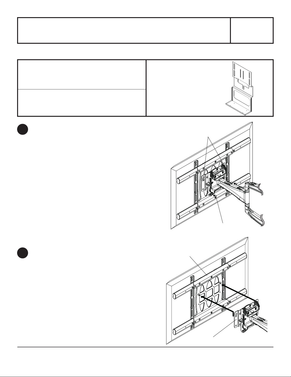
If wall arm (sold separately) has not been
1
mounted, skip to step 3 on page 2.
Remove two M10 x 15 mm screws from bottom
holes of adapter plate. Loosen two M10 x 15 mm
screws from top holes of adapter plate.
Unhook universal or dedicated adapter bracket
2
from adapter plate.
LOOSEN
M10 X 15 MM SCREWS
REMOVE
M10 X 15 MM SCREWS
UNIVERSAL
ADAPTER BRACKET
ADAPTER PLATE
ISSUED: 10-31-10 SHEET #: 120-9091-2 11-08-10
Page 2
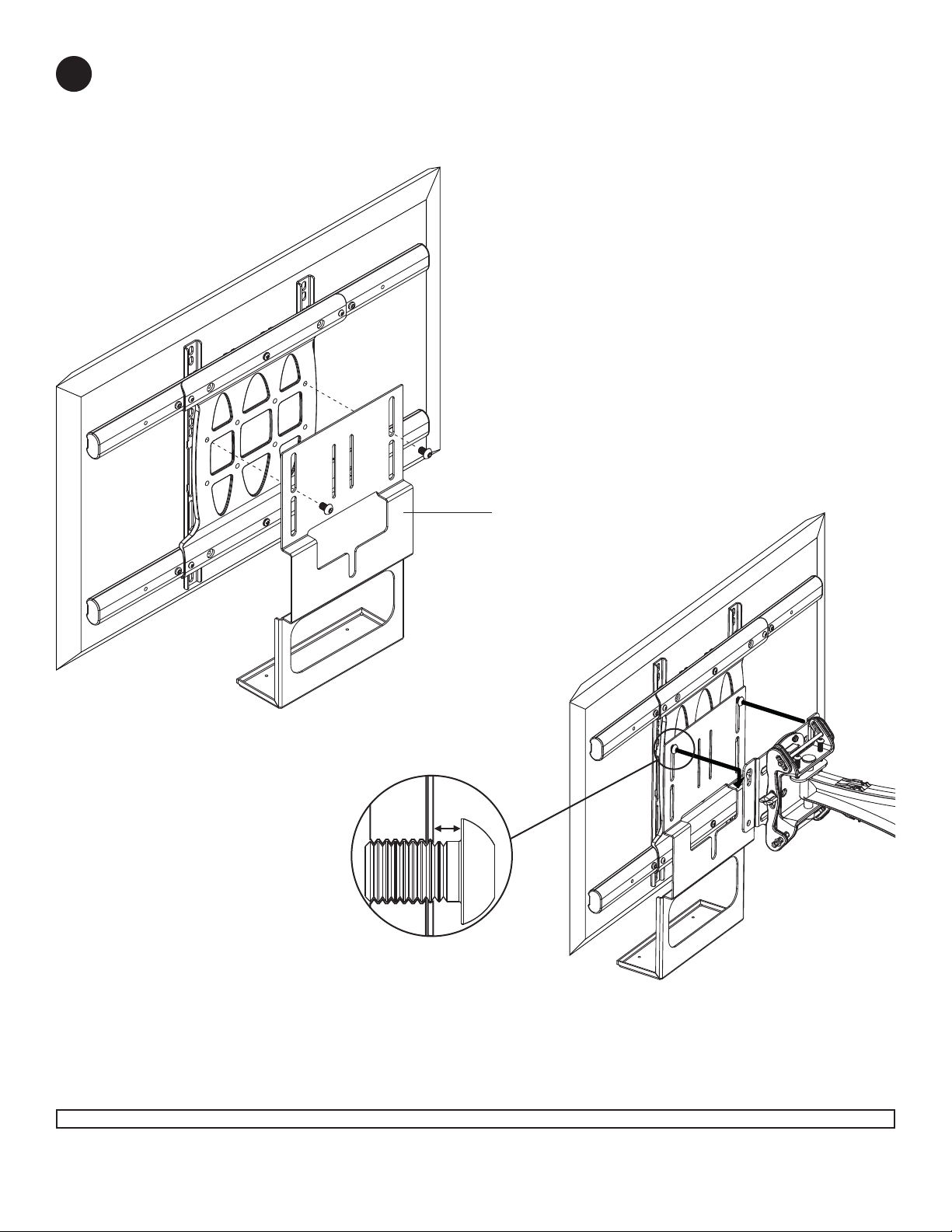
Remove two M10 x 15 mm socket screws from universal adapter bracket. Hand thread two M10 x 15 mm
3
socket screws through top slots of accessory bracket (A) into top holes of universal adapter bracket as shown in
fi gure 3.1 leaving 1/8" of exposed thread as shown in detail 1.
Hook socket screws onto universal adapter bracket as shown in fi gure 3.2.
fi g 3.1
1/8"
DETAIL 1
A
fi g 3.2
2 of 3
Visit the Peerless Web Site at www.peerlessmounts.com For customer care call 1-800-729-0307 or 708-865-8870.
ISSUED: 10-31-10 SHEET #: 120-9091-2 11-08-10
Page 3
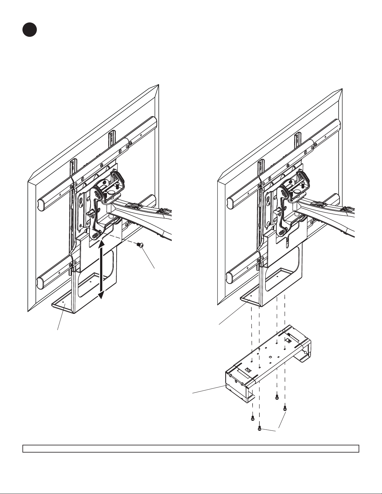
Insert two M10 x 15 mm socket screws into bottom mounting holes of adapter plate as shown in fi gure 4.1.
4
Adjust accessory bracket (A) so bottom tray touches bottom of display and tighten all fasteners using a 6 mm
allen wrench included with wall arm.
Attach DS or VPM component shelf (sold separately) to bottom tray using M5 screws included with DS or VPM
component shelf as shown in fi gure 4.2.
fi g 4.1
fi g 4.2
M10 X 15 MM SCREWS
BOTTOM TRAY
BOTTOM TRAY
DS OR VPM COMPONENT
SHELF (SOLD SEPARATELY)
M5 SCREWS
3 of 3
Visit the Peerless Web Site at www.peerlessmounts.com For customer care call 1-800-729-0307 or 708-865-8870.
All other brand and product names are trademarks or registered trademarks of their respective owners.
ISSUED: 10-31-10 SHEET #: 120-9091-2 11-08-10
© 2010, Peerless Industries, Inc. All rights reserved.
 Loading...