

Page 1
Installation and Assembly:
Security Fasteners For Universal PLP Plates
Models: ACC925
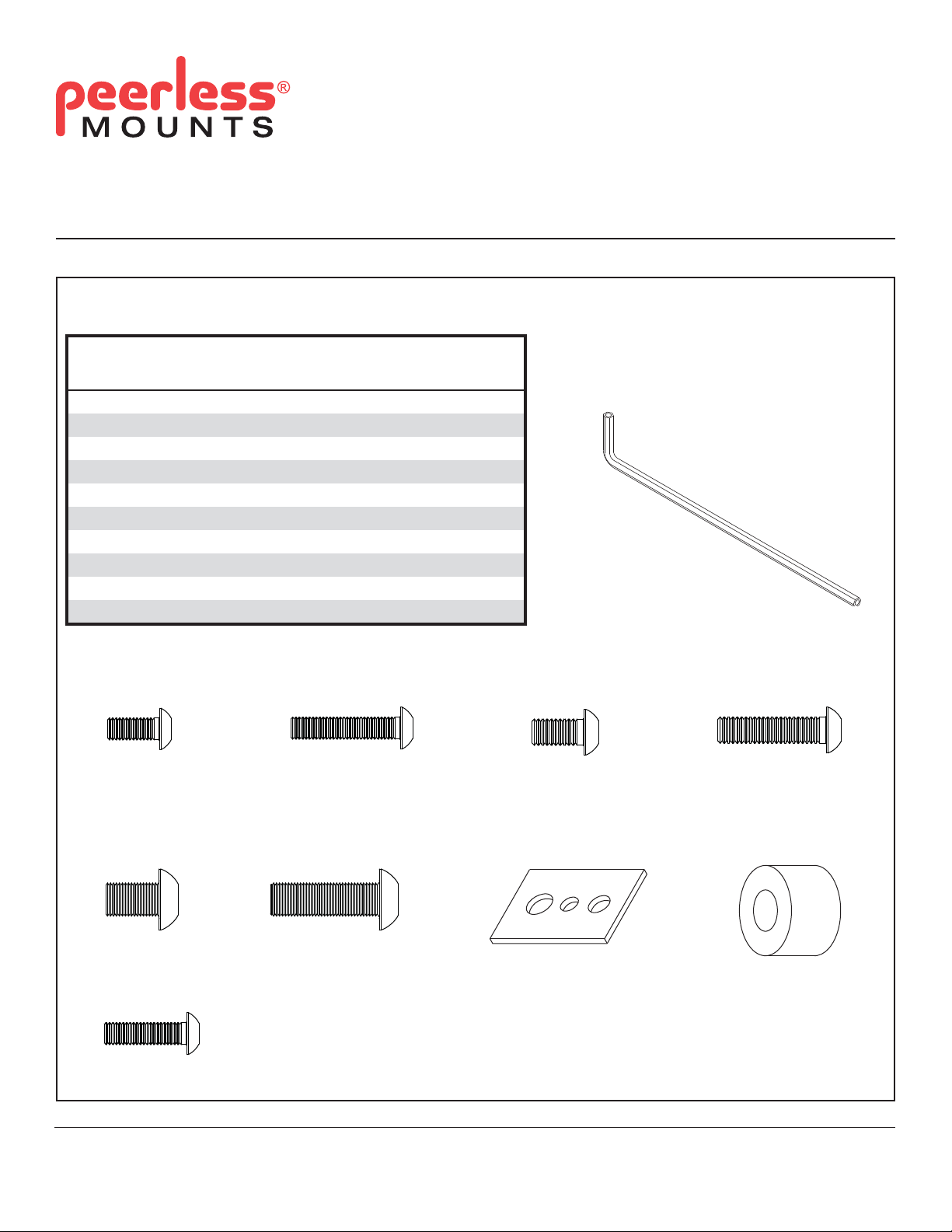
Before you begin, make sure all parts shown are included with your product.
Parts may appear slightly different than illustrated.
Parts List
Description Qty. Part Number
A M5 x 12 mm 4 520-1064
B M5 x 25 mm 6 520-1122
C M6 x 12 mm 4 520-1050
D M6 x 25 mm 4 520-1211
E M8 x 12 mm 4 520-1724
F M8 x 25 mm 4 520-1101
G M5/M4/M6 washer 4 580-1398
H spacer 4 540-1059
4 mm allen wrench
I
J M5 x 20 mm socket pin screw 2 520-1065
1 560-9646
I (1)
A (4)
M5 x 12 mm
E (4)
M8 x 12 mm
J (2)
M5 x 20 mm
B (6)
M5 x 25 mm
F (4)
M8 x 25 mm
C (4)
M6 x 12 mm
G (4)
M5/M4/M6 washer
D (4)
M6 x 25 mm
H (4)
spacer
Visit the Peerless Web Site at www.peerless-av.com
1 of 9
ISSUED: 11-19-08 SHEET #: 120-9062-3 06-29-12
For customer care call 1-800-865-2112.
Page 2
Installing Security Screws for PF and PT wall mount models
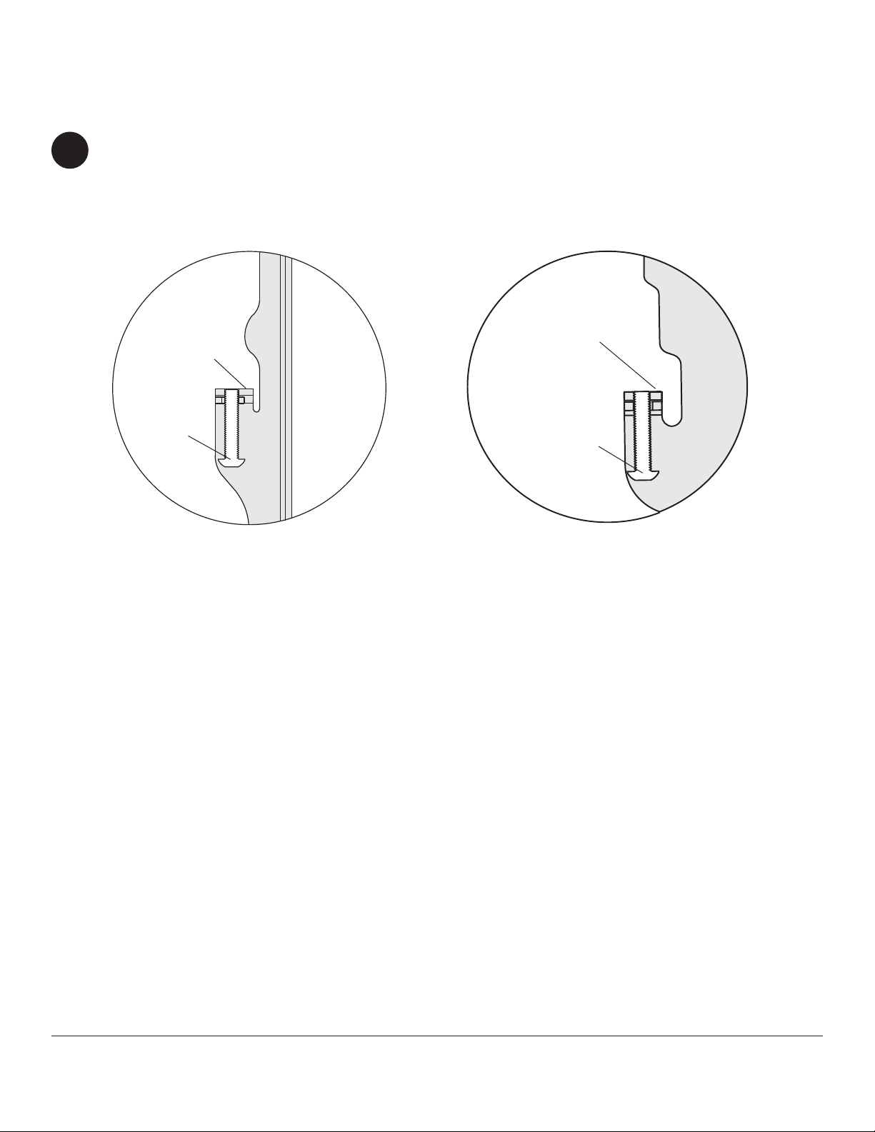
Replacing Safety/Security Screw
NOTE: If installing security screws for SA wall mount models, skip to page 6.
1
Replace safety/security screws with M5 x 25 mm screw (B). Hand thread screw into bottom of flat or tilt adapter
bracket as shown in figure 1.1 and 1.2.
NOTE: Be sure tip of screw is flush with top of adapter bracket hole.
TOP OF
ADAPTER
BRACKET
B
FLAT BRACKETS
TILT BRACKETS
TOP OF
ADAPTER
BRACKET
B
fi g 1.1 fi g 1.2
Visit the Peerless Web Site at www.peerless-av.com
2 of 9
ISSUED: 11-19-08 SHEET #: 120-9062-3 06-29-12
For customer care call 1-800-865-2112.
Page 3
WARNING
• Tighten screws so adapter brackets are fi rmly attached. Do not tighten with excessive force. Overtightening can
cause stress damage to screws, greatly reducing their holding power and possibly causing screw heads to become
detached. Tighten to 40 in. • lb (4.5 N.M.) maximum torque.
• If screws don't get three complete turns in the screen inserts or if screws bottom out and bracket is still not tightly
secured, damage may occur to screen or product may fail.
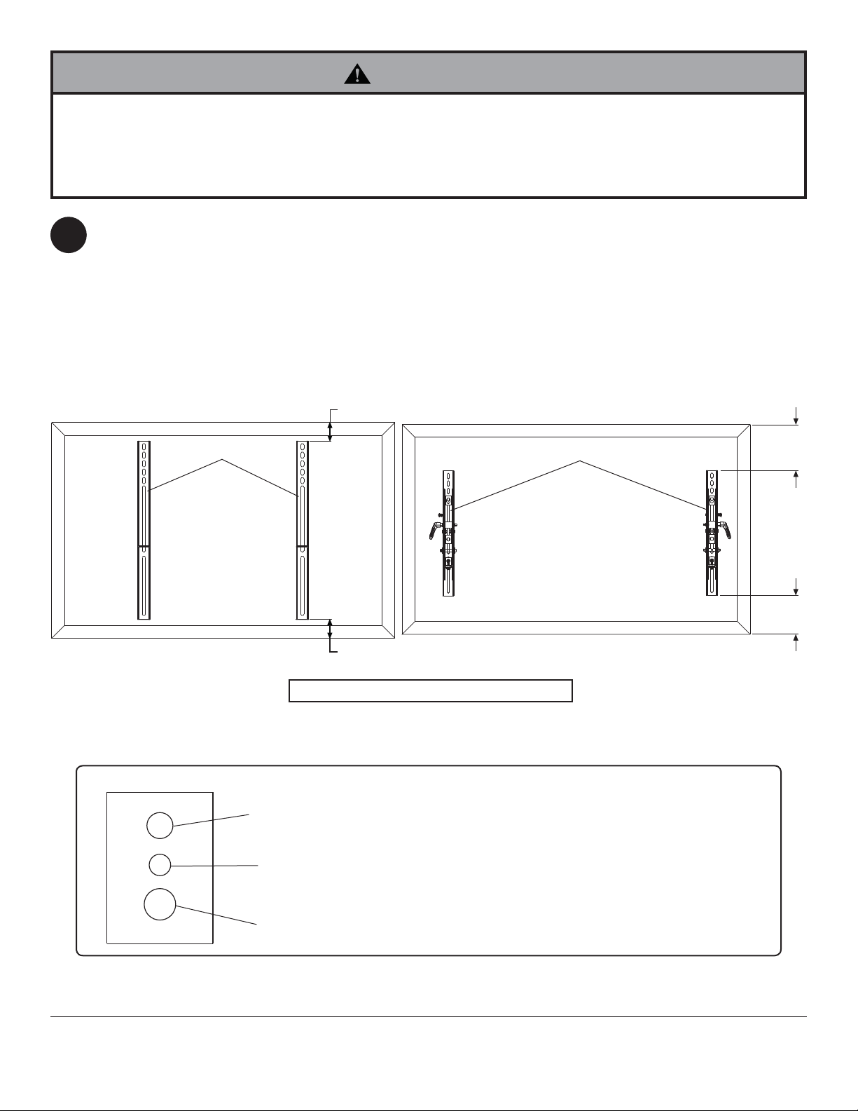
To prevent scratching the screen, set a cloth on a flat, level surface that will support the weight of the screen.
Place screen face side down. If screen has knobs on the back, remove them to allow the adapter brackets to be
2
attached. Place flat or tilt brackets (not included) on back of screen, align to holes, and center on back of screen as
shown below. Attach the adapter brackets to the back of the screen using the appropriate combination of security
screws, multi-washers, and spacers as shown in steps 2-1 and 2-2 on page 4.
NOTE: Top and bottom holes on screen must always be used.
Verify that all holes are properly aligned, and then tighten screws using a phillips screwdriver.
X
FLAT BRACKETS
CENTER BRACKETS
VERTICALLY
ON BACK OF
SCREEN
MULTI-WASHER (E)
X
NOTE: "X" dimensions should be equal.
MEDIUM HOLE FOR M5 SCREWS
SMALL HOLE FOR M4 SCREWS
TILT BRACKETS
CENTER BRACKETS
VERTICALLY
ON BACK OF
SCREEN
Notes:
• The number of fasteners used will vary,
depending upon the type of screen.
• Multi-washers (G) and spacer (H) may
not be used, depending upon the type of
screen.
X
X
LARGE HOLE FOR M6 SCREWS
NOTE: For fl at back screens proceed to step 2-1. For bump-out or recessed back screen skip to step 2-2.
3 of 9
Visit the Peerless Web Site at www.peerless-av.com
• Use the corresponding hole in the multi-
washer that matches your screw size.
ISSUED: 11-19-08 SHEET #: 120-9062-3 06-29-12
For customer care call 1-800-865-2112.
Page 4

For Flat Back Screen
2-1
Begin with the shortest length screw, hand thread through multi-washer and flat or tilt adapter bracket (not
included) into screen as shown below. Screw must make at least three full turns into the mounting hole and fit
snug into place. Do not over tighten. If screw cannot make three full turns into the screen, select a longer length
screw from the security fastener pack. Repeat for remaining mounting holes, level brackets and tighten screws.
NOTE: Spacers may not be used, depending upon the type of screen.
TILT BRACKETSFLAT BRACKETS
SCREEN
MULTI-WASHER
SCREW
FLAT
BRACKET
If you have any questions, please call Peerless customer care at 1-800-865-2112.
For Bump-out or Recessed Back Screen
2-2
Begin with longer length screw, hand thread through multi-washer, flat or tilt adapter bracket (not included) and
spacer in that order into screen as shown below. Screw must make at least three full turns into the mounting hole
and fit snug into place. Do not over tighten. If screw cannot make three full turns into the screen, select a longer
length screw from the security fastener pack. Repeat for remaining mounting holes, level brackets and tighten
screws.
SCREEN
MULTI-WASHER
SCREW
TILT
BRACKET
FLAT BRACKETS
SCREEN
SPACER
FLAT
BRACKET
If you have any questions, please call Peerless customer care at 1-800-865-2112.
Visit the Peerless Web Site at www.peerless-av.com
MULTI-WASHER
SCREW
4 of 9
TILT BRACKETS
SCREEN
MULTI-WASHER
SPACER
SCREW
ADAPTER
BRACKET
ISSUED: 11-19-08 SHEET #: 120-9062-3 06-29-12
For customer care call 1-800-865-2112.
Page 5

Installing Adapter Brackets
WARNING
• Always use an assistant or mechanical lifting equipment to safely lift and position the fl at panel screen.
• Do not tighten screws with excessive force. Overtightening can cause damage to mount. Tighten screws to 40 in. •
lb (4.5 N.M.) maximum torque.
• Be careful not to pinch fi ngers when pushing screen from the bottom.
Hook flat brackets onto wall plate (not included). Then
slowly swing screen in as shown in figure 3.1. Using 4
3
mm security allen wrench (I) turn clockwise until screw
fits firmly against wall plate to prevent screen from
being removed. Screen can be adjusted horizontally by
loosening M5 x 25 mm screw (B) on flat brackets.
NOTE: To lock the screen down, tighten safety/security
screws (B) to wall plate as shown.
To remove screen from mount, loosen safety/security
screws, swing screen away from mount, and lift screen
off of mount.
FLAT BRACKETS
WALL PLATE
3-1
SAFETY/
SECURITY
SCREW (L)
fi g 3.2
Adjust tension in tilt brackets by rotating ratchet handle.
NOTE: If obstruction prevents ratchet handle from rotating,
pull handle out while turning will allow handle to reposition
without tightening. Release and turn handle to tighten or
loosen.
Ratchet handle must be in the up or down position, or
interference will occur while hooking tilt brackets to wall
plate. Slowly hook tilt brackets onto wall plate and swing
screen down. Using 4 mm security allen wrench (I) turn
clockwise until screw fits firmly against wall plate to
prevent screen from being removed as shown in figure 3.3.
To remove screen from mount, loosen safety/security
screws, swing screen away from mount, and lift screen off
of mount.
fi g 3.1
TILT BRACKETS
WALL PLATE
SAFETY/
SECURITY
SCREW (L)
Visit the Peerless Web Site at www.peerless-av.com
5 of 9
fi g 3.3
ISSUED: 11-19-08 SHEET #: 120-9062-3 06-29-12
For customer care call 1-800-865-2112.
Page 6

Installing Security Screws for SA wall mount models
WARNING
• Tighten screws so screen brackets are fi rmly attached to screen. Do not tighten with excessive force. Overtightening
can cause stress damage to screws, greatly reducing their holding power and possibly causing screw heads to
become detached. Tighten to 40 in. • lb (4.5 N.M.) maximum torque.
• If screws don't get three complete turns in the screen inserts or if screws bottom out and bracket is still not tightly
secured, damage may occur to screen or product may fail.
NOTE: Refer to main instructions for adjustments of universal adapter bracket extension brackets.
NOTE: If your screen has a VESA hole pattern skip to page 8.
1
To prevent scratching the screen, set a cloth on a flat, level surface that will support the weight of the screen. Place
screen face side down. Refer to screen manufacturer's instructions for removal of knobs, base, cover, or screw(s)
on the back of the screen to prepare for mounting screen brackets to screen. Adjust screen brackets to align with
screen mounting holes as shown below. Select the small, medium, large or extra large screws from the security
fastener pack then attach screen brackets to screen following steps 1-1 and 1-2 on page 7.
NOTE: Top and bottom mounting holes must be used for attaching screen brackets. Middle holes should also be
used where the fasteners and screens allow.
Verify that all holes are properly aligned, and then tighten screws using a phillips screw driver.
If installing security screws for PF or PT wall mount models, go to page 2.
CENTER SCREEN BRACKETS VERTICALLY ON BACK OF SCREEN
SCREEN
SCREEN BRACKETS
MULTI-WASHER (E)
YY
NOTE: "X" dimensions should be equal.
"Y" dimensions should be equal.
MEDIUM HOLE FOR M5 SCREWS
SMALL HOLE FOR M4 SCREWS
ADAPTER BRACKETS
Notes:
• The number of fasteners used will vary,
depending upon the type of screen.
• Multi-washers (G) and spacer (H) may
not be used, depending upon the type of
screen.
X
X
LARGE HOLE FOR M6 SCREWS
NOTE: For fl at back screens proceed to step 1-1. For bump-out or recessed back screen skip to step 1-2.
6 of 9
Visit the Peerless Web Site at www.peerless-av.com
• Use the corresponding hole in the multi-
washer that matches your screw size.
ISSUED: 11-19-08 SHEET #: 120-9062-3 06-29-12
For customer care call 1-800-865-2112.
Page 7

For Flat Back Screen
Begin with the shortest length screw, hand thread screw through multi-washer and screen brackets (not included)
1-1
into screen as shown below. Screw must make at least three full turns into the mounting hole and fi t snug into
place. Do not over tighten. If screw cannot make three full turns into the screen, select a longer length screw from
the fastener pack. Repeat for remaining mounting holes, level screen brackets and tighten screws.
NOTE: Spacers may not be used, depending upon the type of screen.
If you have any questions, please call Peerless customer care at 1-800-865-2112.
SCREEN
MULTI-WASHER
SCREW
SCREEN
BRACKET
For Bump-out or Recessed Back Screen
Begin with longer length screw, hand thread screw through multi-washer, screen brackets (not included) and
1-2
spacer in that order into screen as shown below. Screw must make at least three full turns into the mounting hole
and fi t snug into place. Do not over tighten. If screw cannot make three full turns into the screen, select a longer
length screw from the fastener pack. Repeat for remaining mounting holes, level screen brackets and tighten
screws.
If you have any questions, please call Peerless customer care at 1-800-865-2112.
SCREEN
SPACER
SCREEN
BRACKET
MULTI-WASHER
SCREW
Visit the Peerless Web Site at www.peerless-av.com
7 of 9
ISSUED: 11-19-08 SHEET #: 120-9062-3 06-29-12
For customer care call 1-800-865-2112.
Page 8

Attaching Adapter Plate to Screen with VESA® Mounting Pattern
Choose hole pattern as shown in detail 1 for VESA mounting pattern. Begin with the shortest length screw, hand
2
thread through adapter plate into screen as shown in detail 2. Screw must make at least three full turns into the
mounting hole and fi t snug into place. Do not over tighten. If screw cannot make three full turns into the screen,
select a longer length screw from the fastener pack. Repeat for remaining mounting holes. Securely tighten screws.
NOTE: Spacers may not be used, depending upon the type of screen.
If you have any questions, please call Peerless customer care at 1-800-865-2112.
Mounting Patterns
VESA
®
100 x 100
SCREEN
ADAPTER
PLATE
VESA
VESA
NOTE: For screens
with a hole pattern in
a pocket, spacers go
between adapter plate
and screen.
®
200 x 100
®
200 x 100 VESA® 200 x 200VESA® 100 x 100
SCREEN
VESA
®
200 x 200
DETAIL 1
SCREEN
DETAIL 2
Visit the Peerless Web Site at www.peerless-av.com
8 of 9
ISSUED: 11-19-08 SHEET #: 120-9062-3 06-29-12
For customer care call 1-800-865-2112.
Page 9

WARNING
• Do not lift more weight than you can handle. Use additional man power or mechanical lifting equipment to safely
handle placement of the screen.
• Failure to l
cause screen to come off mount if hit accidentally.
ock brake pad with two M5 x 20 mm screws (J) and lock tilt bracket with M5 x 25 mm screw (B) can
Installing and Removing Flat Panel Screen
To attach screen to arm (not included), insert the puck of
3
adapter plate into the tilt bracket slot as shown in fi gure
3.1. Attach brake pad assembly as shown in Detail 3
so that the brake pad is snug against the adapter plate.
Adjust roll position of adapter plate to level screen then
lock puck in place by tightening M5 x 25 mm screw (B) on
the underside of tilt bracket using 4 mm allen wrench (I).
Tig
hten all (M5 x 20 mm, M5 x 25 mm) screws.
NOTE: To remove screen from arm, remove two
M5 x 20 mm screws (J) and brake pad. Lift screen out of
tilt bracket.
CAUTION
• Do not tighten screws with excessive force. Overtightening
can cause damage to mount. Tighten M5 x 20 mm screws (J)
to 20 in. • lb (2.26 N.M.) maximum torque.
DETAIL 3
J
BRAKE PAD
ADAPTER PLATE
PUCK
TILT
BRACKET
ARM
B
fi g. 3.1
Visit the Peerless Web Site at www.peerless-av.com
9 of 9
All other brand and product names are trademarks or registered trademarks of their respective owners.
ISSUED: 11-19-08 SHEET #: 120-9062-3 06-29-12
For customer care call 1-800-865-2112.
© 2012, Peerless Industries, Inc. All rights reserved.
 Loading...