

Page 1
Installation and Assembly -
Metal Stud Accessory Kit for
LCL, LCS, and LCA Models
Model: ACC 908
Read instruction sheet before you start installation and assembly.
Before you start check the parts list to insure all of the parts shown are included.
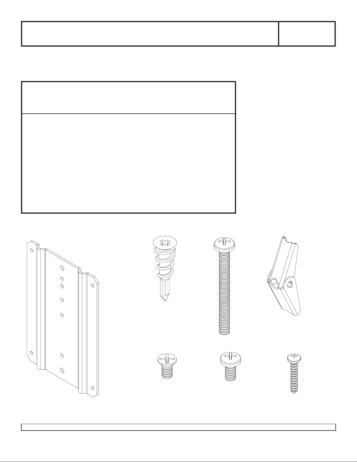
Parts List
Description Qty . Part Number
A metal stud wall plate 1 095-4173
B zip-it drywall anchor 4 590-2107
C 1/4-20 x 2.5" round head phillips screw 2 520-9522
D 1/4-20 toggler 2 590-1093
E 1/4-20 x 1/2" flat head phillips screw 2 520-2178
F 1/4-20 x 1/2" pan head phillips screw 2 520-951 1
G #8 x 1" pan head phillips sheet metal screw 4 520-2179
Note: Some parts may appear slightly different than illustrated.
Maximum Load Capacity:
25 lb (11.4 kg)
A
Visit the Peerless Web Site at www.peerlessindustries.com
B
D
C
E
F
G
1 of 5 ISSUED: 04-28-03 SHEET #: 095-9161-3 08-16-04
For customer service call 1-800-729-0307 or 708-865-8870.
Page 2
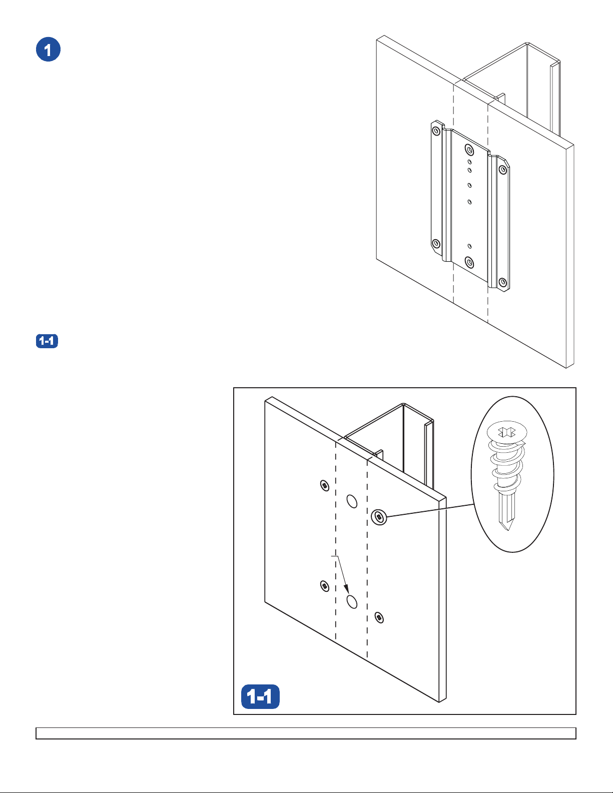
Use stud finder to locate center of metal stud. Place and level
metal stud wall plate (A) on wall and mark the centers of the
six circled holes on the wall as shown right.
DRYWALL
A
MET AL
STUD
Drill two 11/16" (17 mm) dia. holes through
stud. Screw four zip-it drywall anchors (B) in the four marked
corner holes as shown below .
center of metal
11/16" dia. hole
(2 plcs.)
B
Visit the Peerless Web Site at www.peerlessindustries.com
2 of 5 ISSUED: 04-28-03 SHEET #: 095-9161-3 08-16-04
For customer service call 1-800-729-0307 or 708-865-8870.
Page 3

Attach metal stud wall plate (A) to center of metal
stud using two 1/4-20 x 2.5" phillips screws (C) and
two 1/4-20 togglers (D) as shown below and in
Illustration A, but do not tighten until after the metal
stud wall plate (A) is securely fastened in step 3.
WARNING
• Product must be mounted through drywall that has a
minimum thickness of 1/2" and into metal studs, 26
gauge or heavier.
ILLUSTRATION A
C
A
Place screw (C) through
Partially fasten toggler (D) to back of screw. Pivot
toggler ends 90° and push through hole in drywall.
DRYWALL
D
DRYWALL
metal stud wall plate (A).
METAL STUD
C
D
C
Fasten metal stud wall plate (A) using four #8 x 1"
phillips sheet metal screws (G) as shown. Securely
tighten two 1/4-20 x 2.5" phillips screws (C).
A
Pull screw (C) back until toggler (D) is flush with
metal stud and hold. Thread screw through with
fingers and loosely tighten.
D
Visit the Peerless Web Site at www.peerlessindustries.com
C
A
G
3 of 5 ISSUED: 04-28-03 SHEET #: 095-9161-3 08-16-04
For customer service call 1-800-729-0307 or 708-865-8870.
Page 4

Instructions for mounting a Peerless® LCD screen mount model
LCS or LCL (articulating wall ar m) with a 5 1/2" wall plate
Attach wall plate to metal stud wall plate (A) using two 1/4-20 x 1/2" flat
head phillips screws (E) where indicated right and marked in detail 1.
TOP OF WALL PLATE
WALL
PLATE
A
A
CUTAWAY
OF LCL/LCS
MODEL
E
DETAIL 1
(FRONT VIEW)
Instructions for mounting a Peerless® LCD screen mount model
LCS or LCL (articulating wall ar m) with a 4 1/4" wall plate
Attach wall plate to metal stud wall plate (A) using two 1/4-20 x 1/2” flat
head phillips screws (E) where indicated right and marked in detail 2.
TOP OF WALL PLATE
WALL
PLATE
CUTAWAY
A
OF LCL/LCS
MODEL
A
DETAIL 2
(FRONT VIEW)
Visit the Peerless Web Site at www.peerlessindustries.com
E
4 of 5 ISSUED: 04-28-03 SHEET #: 095-9161-3 08-16-04
For customer service call 1-800-729-0307 or 708-865-8870.
Page 5

Instructions for mounting a Peerless LCD
screen mount model LCA Large (swing ar m)
Attach wall plate to metal stud wall plate (A) using two 1/4-20 x 1/2" pan head
phillips screws (F) where indicated right and marked in detail 3.
TOP OF WALL PLATE
WALL
PLATE
CUTAWAY OF LCA
LARGE MODEL
A
F
DETAIL 3
(FRONT VIEW)
Instructions for mounting a Peerless LCD screen
mount model LCA Small or Medium (swing arm)
Attach wall plate to metal stud wall plate (A) using two 1/4-20 x 1/2" pan head
phillips screws (F) where indicated right and marked in detail 4.
TOP OF WALL PLATE
A
A
CUTAWAY OF LCA
SMALL MODEL
DETAIL 4
(FRONT VIEW)
5 of 5 ISSUED: 04-28-03 SHEET #: 095-9161-3 08-16-04
Visit the Peerless Web Site at www.peerlessindustries.com
© 2004 Peerless Industries, Inc. All rights reserved.
Peerless is a registered trademarks of Peerless Industries, Inc.
All other brand and product names are trademarks or registered trademarks of their respective owners.
WALL
PLATE
A
F
For customer service call 1-800-729-0307 or 708-865-8870.
 Loading...