

Page 1

Installation and Assembly - Round Ceiling Plate
Models: ACC570, ACC570S,
ACC570W
NOTE: Read entire instruction sheet before beginning installation and
assembly.
Before you begin, make sure all parts shown are included with your product.
Parts Li st
De scri p ti o n Qty. Par t # Part # Part #
round ceiling plate 1 055-1798 055-4798 055-2798
A
#14 x 2. 5" wood s crew 4 5S1-015-C03 5S1-015-C04 5S1-015-C04
B
M5 x .8 x 10 mm phillips screw 1 520-9250 520-2005 520-2005
C
M5 x . 8 x 10 m m sock et pin screw 1 520-1 164 520-2031 520 -203 1
D
4 mm al len wrenc h 1 560-9646 560-9646 560-9646
E
rubber grommet 1 530-9401 530-9401 530-9401
F
conc ret e anc hor 4 590-0097 590-0097 590-0097
G
AB
ACC 570 ACC 570S ACC 570W
C
This product is UL Listed. It must be
installed by a qualified professional
installer.
Maximum UL Load Capacity: 150 lb (68 kg)
D
R
E
F
Parts may appear slightly different than illustrated.
G
WARNING
• Do not begin to install your Peerless product until you have read and understood the instructions and warnings
contained in this Installation Sheet. If you have any questions regarding any of the instructions or warnings, please
call Peerless customer care at 1-800-865-21 12.
• This product should only be installed by someone of good mechanical aptitude, has experience with basic building
construction, and fully understands these instructions.
• Make sure that the supporting surface will safely support the combined load of the equipment and all attached
hardware and components.
• Never exceed the Maximum UL Load Capacity.
• If mounting to wood joists or wood beam ceilings, make sure that mounting screws are anchored into the center of
the joists or beams. Use of an "edge to edge" stud finder is highly recommended.
• Always use an assistant or mechanical lifting equipment to safely lift and position equipment.
• Tighten screws firmly, but do not overtighten. Overtightening can damage the items, greatly reducing their holding
power.
1 of 4
Visit the Peerless Web Site at www.peerlessmounts.com For customer care call 1-800-729-0307 or 708-865-8870.
ISSUED: 11-14-07 SHEET #: 054-9054-5
Page 2
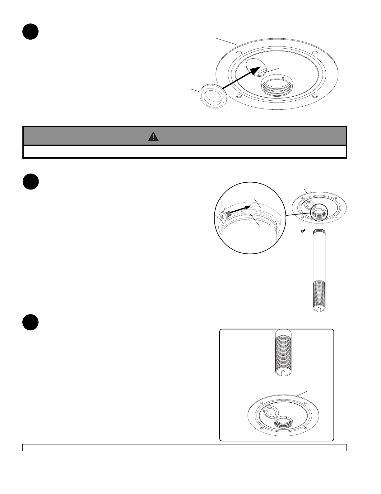
Place grommet (F) into hole of ceiling plate (A).
1
NOTE: Make sure grommet overlaps retaining
collar. Grommet may require some force to fit in
hole and will appear slightly deformed.
A
F
WARNING
• For safety, extension column must be locked to threaded fitting with screw .
Extension Column Applications
Insert end of extension column into threaded fitting of
2
ceiling plate (A). Tighten four or five complete turns.
Align slot in extension column with one of the small
holes in the side of the threaded fitting. Insert and
tighten one M5 x 10 mm phillips screw (C) into hole to
lock extension column to threaded fitting.
C
THREADED
FITTING
RETAINING
COLLAR
A
NOTE: For security option, use M5 socket pin screw (D)
in place of screw (C). Tighten using 4 mm allen
wrench (E).
Flush Mounting Applications
Screw flush mount from top of ceiling plate (A) as
2
shown in fig. 2. Tighten four or five complete turns.
Align slot in flush mount tube with one of the small
holes in the side of the threaded fitting. Insert and
tighten one M5 x 10 mm phillips screw (C) into hole to
lock flush mount tube to threaded fitting.
NOTE: For security option, use M5 socket pin
screw (D) in place of screw (C). Tighten using 4 mm
allen wrench (E).
SLOT
EXTENSION
COLUMN
(SOLD
SEP ARATELY)
fig. 2
FLUSH MOUNT
TUBE (SOLD
SEPARATELY)
A
2 of 4
Visit the Peerless Web Site at www.peerlessmounts.com For customer care call 1-800-729-0307 or 708-865-8870.
ISSUED: 11-14-07 SHEET #: 054-9054-5
Page 3

Installation to Wood Joist Finished Ceilings, Exposed Wood Joists,
or Wood Beam Ceilings
WARNING
• Installer must verify that the supporting surface will safely support the combined load of the equipment and all
attached hardware and components.
• Tighten wood screws so that ceiling plate is firmly attached, but do not overtighten. Overtightening can damage
the screws, greatly reducing their holding power.
• Never tighten in excess of 80 in. • lb (9 N.M.).
• Make sure that mounting screws are anchored into the center of the wood joist or wood beam. The use of an
"edge to edge" stud finder is highly recommended.
• Hardware provided is for attachment of mount through standard thickness drywall or plaster into wood joist or
wood beam ceilings. Installers are responsible to provide hardware for other types of mounting situations.
Drill two 5/32" (4 mm) dia. holes to a minimum depth of 2.5" (64 mm). Attach ceiling plate (A) to the joist center
3
using two #14 x 2.5" wood screws (B) as shown. Tighten wood screws (B) using 3/8" (10 mm) socket wrench so
ceiling plate (A) is firmly attached.
A
B
3 of 4
Visit the Peerless Web Site at www.peerlessmounts.com For customer care call 1-800-729-0307 or 708-865-8870.
ISSUED: 11-14-07 SHEET #: 054-9054-5
Page 4

Installation to Solid Concrete or Cinder Block
WARNING
• When installing Peerless ceiling plates on cinder block, verify that you have a minimum of 1-3/8" of actual
concrete thickness in the hole to be used for the concrete anchors. Do not drill into mortar joints! Be sure to
mount in a solid part of the block, generally 1" minimum from the side of the block. Cinder block must meet
ASTM C-90 specifications. It is suggested that a st andard electric drill on slow setting is used to drill the hole
instead of a hammer drill to avoid breaking out the back of the hole when entering a void or cavity .
• Concrete must be 2000 psi density minimum. Lighter density concrete may not hold concrete anchor.
• Make sure that the supporting surface will safely support the combined load of the equipment and all attached
hardware and components.
Use ceiling plate (A) as a template to mark holes.
3
Drill four 1/4" (6 mm) dia. holes to a minimum depth
of 2.5" (64 mm). Insert four anchors (G) in holes
flush with ceiling as shown in figure 3.1.
Place ceiling plate (A) over anchors (G) and secure
with #14 x 2.5" (6 mm x 65 mm) wood screws (B).
Tighten wood screws (B) using 3/8" (10 mm) socket
wrench to firmly attach ceiling plate (A).
See figures 3.2 and 3.3.
WARNING
• Always attach concrete anchors directly to load-bearing
concrete.
• Never attach concrete anchors to concrete covered with
plaster, drywall, or other finishing material. If mounting
to concrete surfaces covered with a finishing surface is
unavoidable, the finishing surface must be counterbored
as shown below. Be sure concrete anchors do not pull
away from concrete when tightening screws. If plaster/
drywall is thicker than 5/8", custom fasteners must be
supplied by installer . (Not evaluated by UL)
fig. 3.1
CONCRETE
CEILING
G
Drill holes and insert anchors (G).
fig. 3.2
A
B
Place ceiling plate (A) over anchors (G) and secure with
screws (B).
G
fig. 3.3
WARNING
Tighten all fasteners.
• Tighten screws so that ceiling plate is firmly attached,
but do not overtighten. Overtightening can damage
screws, greatly reducing their holding power.
• Never tighten in excess of 80 in. • lb (9 N.M.).
INCORRECT CORRECT
ceiling
plate
plaster/
CUT AW A Y VIEW
Visit the Peerless Web Site at www.peerlessmounts.com For customer care call 1-800-729-0307 or 708-865-8870.
dry wall
concrete
ceiling
plate
plaster/
dry wall
concrete
A
B
4 of 4
All other brand and product names are trademarks or registered trademarks of their respective owners.
ISSUED: 11-14-07 SHEET #: 054-9054-5
© 2007, Peerless Industries, Inc. All rights reserved.
G
 Loading...