

Page 1
Installation and Assembly - Ceiling Plate
Model: ACC 560
Note: Read entire instruction sheet before beginning installation and assembly.
Maximum load capacity:
50 lb (22.7 kg)
WARNING
• Installer must verify that the supporting surface will safely support the combined weight of mount and projector .
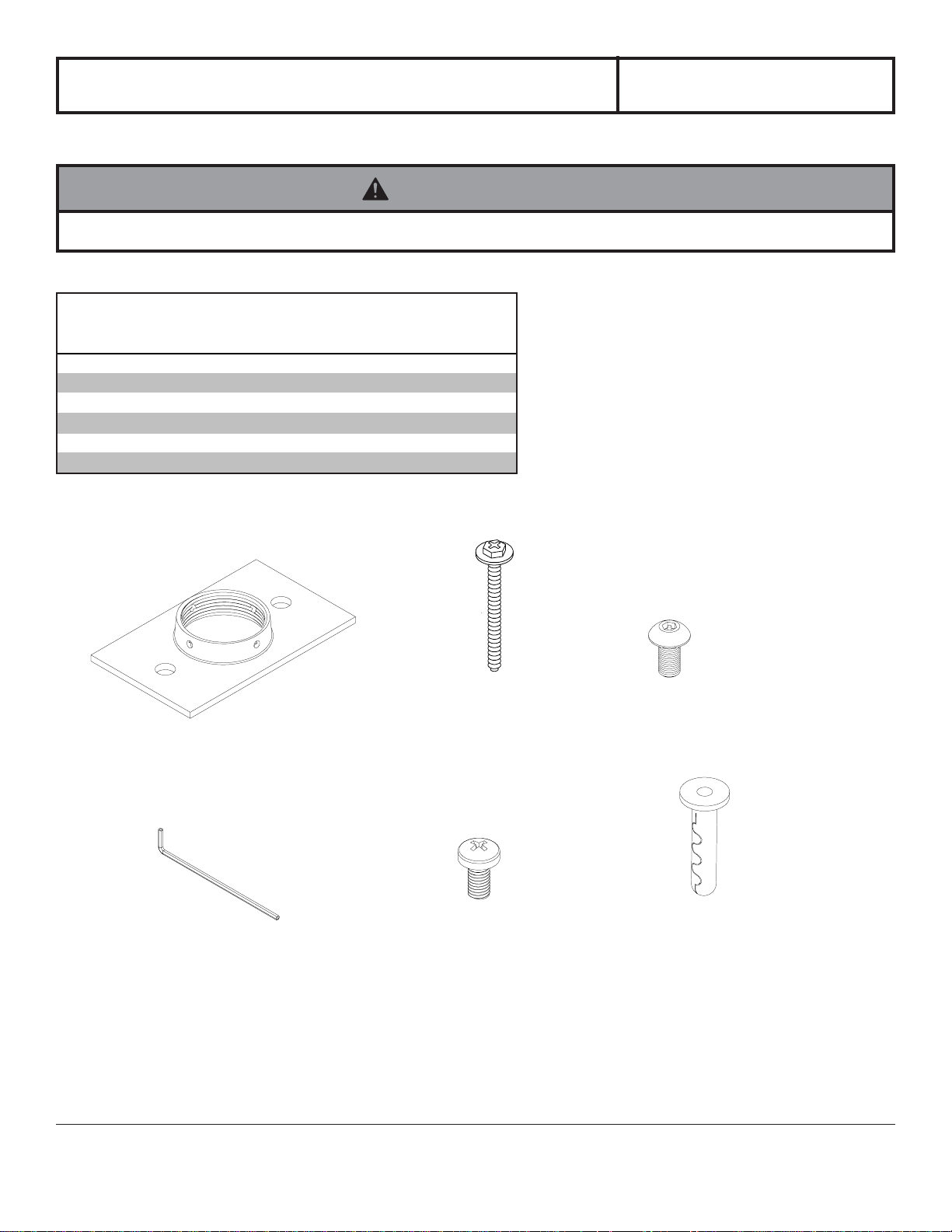
Parts List
De scrip tion Qty. Part #
ceil i ng plat e 1 580-1042
A
#14 x 2. 5" (6 mm x 65 mm) wood screw 2 5S1-015-C03
B
M5 x .8 x 10 mm socket pin screw 1 520-1164
C
4 mm all en wrench 1 560-9646
D
M5 x . 8 x 10 m m phil l ips screw 1 520-9250
E
alligat or® anchor 2 590-0097
F
A
B
C
D
E
1 of 4
Visit the Peerless Web Site at www.peerlessmounts.com For customer care call 1-800-865-2112 or 708-865-8870.
ISSUED: 02-06-07 SHEET #: 054-9125-2 07-30-07
F
Page 2
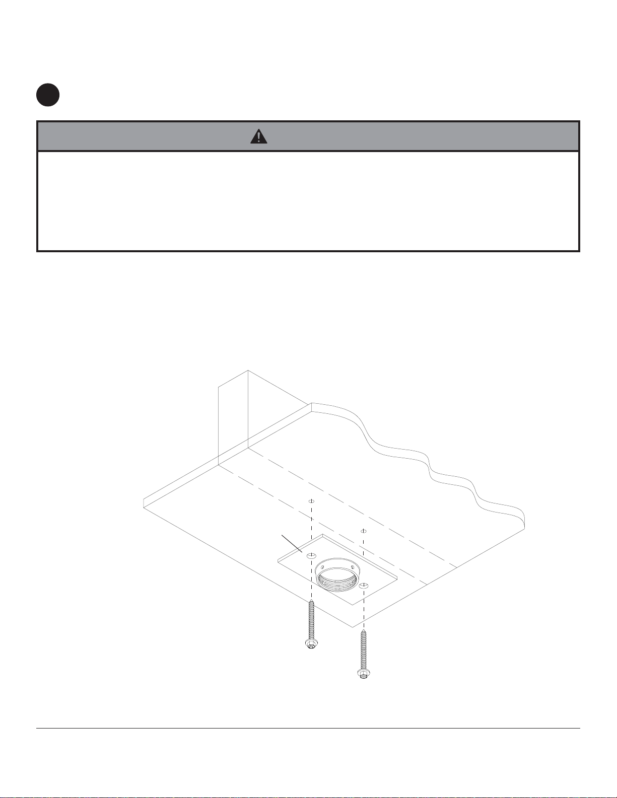
Installation To Wood Joist Finished Ceilings,
Exposed Wood Joists, or Wood Beam Ceilings
Drill two 5/32" (4 mm) dia. holes to a minimum depth of 2.5" (64 mm). Attach ceiling plate (A) with two #14 x 2.5" (6
1
mm x 65 mm) wood screws (B) as shown using 3/8" (10 mm) socket wrench.
WARNING
• Installer must verify that the supporting surface will safely support the combined weight of mount and projector .
• Tighten wood screws so that ceiling plate is firmly attached, but do not overtighten. Overtightening can damage the
screws, greatly reducing their holding power.
• Never tighten in excess of 80 in • lb (9 N.M.).
• Make sure that mounting screws are anchored into the center of the studs. The use of an "edge to edge" stud finder is
highly recommended.
IMPORTANT: Be sure to drill holes into the joist CENTER!
WOOD JOIST
A
B
CEILING
B
2 of 4
Visit the Peerless Web Site at www.peerlessmounts.com For customer care call 1-800-865-2112 or 708-865-8870.
ISSUED: 02-06-07 SHEET #: 054-9125-2 07-30-07
Page 3

WARNING
• When installing Peerless wall mounts on concrete, verify that you have a minimum of 1 5/8" of actual concrete surface
in the 1/4" diameter hole to be used for the concrete anchors. Do not drill into mortar joints! Concrete must meet
ASTM C-90 specifications.
• Concrete must be 2000 psi density minimum. Lighter density concrete may not hold concrete anchor .
• Installer must verify that the supporting surface will safely support the combined weight of mount and projector .
• Never exceed the Maximum Load Capacity of 50 lb (22.7 kg).
Installation to Concrete Ceilings
Drill two 1/4" (6 mm) dia. holes to a minimum depth of
1
2.5" (64 mm). Attach ceiling plate (A) using two
concrete anchors (F) and two #14 x 2.5" wood screws
(B) as shown in Illustration A and 1, 2, and 3 (below).
Tighten all fasteners.
CONCRETE CEILING
WARNING
• Tighten wood screws so that wall plate is firmly
attached, but do not overtighten. Overtightening can
damage the screws, greatly reducing their holding
power.
• Never tighten in excess of 80 in • lb (9 N.M.).
• Make sure that mounting screws are anchored into the
center of the studs. The use of an "edge to edge" stud
finder is highly recommended.
F
A
B
1
concrete
ceiling
F
Drill hole and insert anchor
2
Place ceiling plate over anchor and secure with screw
A
B
F
• FOR DIRECT A TT ACHMENT TO LOAD BEARING
CONCRETE ONL Y! Concrete expansion anchors are
not intended for attachment to concrete ceilings
covered with a layer of plaster, drywall, or other
finishing material. If mounting to concrete ceiling
covered with plaster / drywall is unavoidable, plaster /
drywall must be counterbored as shown below.
Illustration A
WARNING
3
INCORRECT
F
B
After repeating step one tighten all fasteners
3 of 4
Visit the Peerless Web Site at www.peerlessmounts.com For customer care call 1-800-865-2112 or 708-865-8870.
CUT AW A Y VIEW
metal
bracket
concrete
plaster/
dry wall
ISSUED: 02-06-07 SHEET #: 054-9125-2 07-30-07
metal
bracket
CORRECT
concrete
plaster/
dry wall
Page 4

Installation to Extension Column
Screw extension column to ceiling plate (A). Align the notch with one of the four holes in the ceiling plate (A) and
2
secure extension column with a M5 x 10 phillips screw (E) or a M5 x 10 mm socket pin screw (C) using security allen
wrench (D). See detail 1.
A
E or C
A
EXTENSION COLUMN
(UL Listed EXT or ADJ Series)
Sold Separately
EXTENSION COLUMN
SLOT
DETAIL 1
4 of 4
Visit the Peerless Web Site at www.peerlessmounts.com For customer care call 1-800-865-2112 or 708-865-8870.
© 2007, Peerless Industries, Inc. All rights reserved.
All other brand and product names are trademarks or registered trademarks of their respective owners.
ISSUED: 02-06-07 SHEET #: 054-9125-2 07-30-07
 Loading...