

Page 1
Installation and Assembly - Cathedral Ceiling Adapter
Model: ACC 556
Note: Read entire instruction sheet before beginning
installation and assembly.
IMPORT ANT! Certain ceilings require additional mounting hardware...
CEILING CONSTRUCTION ADDITIONAL HARDWARE REQUIRED
Wood Joist, Wood Beam none
Concrete, Concrete Anchor Kit - order accessory kit ACC 200.
Note: Some units may already include concrete anchors.
Other or unsure? Consult a qualified professional installer or call
Peerless Customer Service.
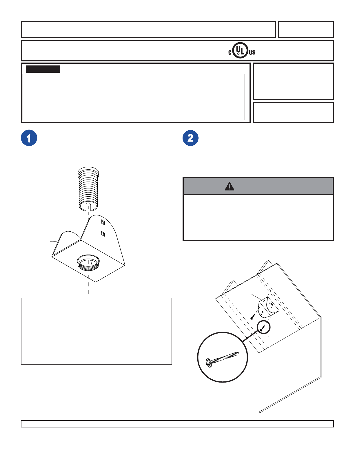
Fully thread flush mount tube into threaded fitting in
lower ceiling bracket (B).
Note: If you will install an extension column do not
install flush mount tube. Begin with step 2.
For Wood Joist Finished Ceiling, Exposed Wood
Joists, or Wood Beam Ceiling. (See for concrete
ceilings). Drill two 5/32" (4 mm) dia. holes to a
minimum depth of 2.5" (64 mm). Attach upper ceiling
bracket (A) with two #14 x 2.5" (6 mm x 65 mm)
wood screws (F).
Flush Mount
Tube (included
with Jumbo
Mount Bracket)
• Tighten wood screws so that ceiling bracket is firmly
attached, but do not overtighten. Overtightening can
damage the screws, greatly reducing their holding
power.
• Never tighten in excess of 80 in. • lb (9 N.M.).
B
This product is intended for use with UL
R
Listed products and must be installed by a
qualified professional installer.
For customer service, or to
order accessory kits call
1-800-729-0307 or
708-865-8870
Max. Load Capacity:
300 lb (137 kg)
WARNING
joist
A
ceiling
PARTS LIST
PART # QTY. DESCRIPTION
A 1465-273 1 upper ceiling bracket
B 2JM-11CP01L 1 lower ceiling bracket
C 520-9215 4 3/8-16 x 3/4" carriage bolt
D 540-9407 4 flat washer
E 530-9310 4 3/8-16 nylock nut
F 5S1-015-C04 2 #14 x 2.5" (6mm x 65mm) wood screw
G 520-9250 1 M5 x .8 x 10mm phillips screw (for use
with extension column if applicable)
1 of 3
Visit the Peerless Web Site at www.peerlessindustries.com For customer service call 1-800-729-0307 or 708-865-8870.
F
wall
ISSUED: 01-11-93 SHEET #: 128-9007-2 11-16-04
Page 2
WARNING
• Concrete must be 2000 psi density minimum. Lighter density concrete may not hold concrete anchor .
• Make sure that the ceiling will safely support four times the combined load of the equipment and all attached hardware
and components.
WARNING
• Make sure that the ceiling will safely support the
combined load of the equipment and all attached
hardware and components.
• Never exceed the Max. Load Capacity of 300 lb (137 kg).
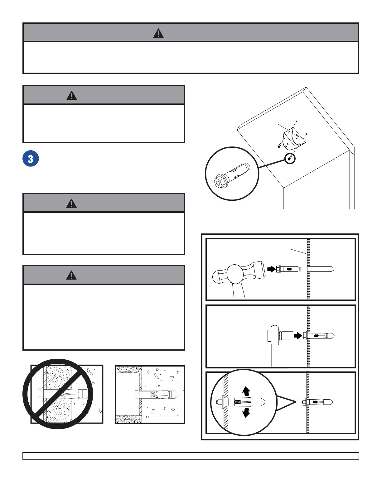
For Concrete Ceilings drill four 5/16" (8 mm) dia.
holes to a minimum depth of 1-3/4" (45 mm). Attach
upper ceiling bracket (A) using concrete expansion
anchors as shown (right). Tighten to 80 in. • lb (9
N.M.) maximum torque.
WARNING
• Tighten concrete anchor bolt firmly , but do not overtighten. Overtightening can damage the bolt, greatly
reducing its holding power.
• Never tighten in excess of 80 in. • lb (9 N.M.).
WARNING
A
CONCRETE ANCHOR INSTALLA TION
1
CEILING PLATE
ceiling
wall
CEILING
• Always attach concrete expansion anchors directly to
load-bearing concrete.
• Never attach concrete expansion anchors to concrete
covered with plaster, drywall or other finishing material.
If mounting to concrete surfaces covered with a
finishing surface is unavoidable, the finishing surface
must be counterbored as shown in Figure 1.
2
3
Figure 1
2 of 3
Visit the Peerless Web Site at www.peerlessindustries.com For customer service call 1-800-729-0307 or 708-865-8870.
ISSUED: 01-11-93 SHEET #: 128-9007-2 11-16-04
Page 3

Insert two carriage bolts (C) into
upper ceiling bracket (A) and
two carriage bolts into lower
ceiling bracket (B).
ceiling
A
B
C
Attach lower ceiling bracket (B)
to upper ceiling bracket (A) using
four flat washers (D) and nylock
nuts (E). Tighten all nuts.
Note: use a level to make sure
lower ceiling bracket (B) is level.
ceiling
A
B
E
D
3 of 3
Visit the Peerless Web Site at www.peerlessindustries.com For customer service call 1-800-729-0307 or 708-865-8870.
© 2004 Peerless Industries, Inc. All rights reserved.
Peerless is a registered trademark of Peerless Industries, Inc.
All other brand and product names are trademarks or registered trademarks of their respective owners.
ISSUED: 01-11-93 SHEET #: 128-9007-2 11-16-04
 Loading...