

Page 1
Installation & Assembly - Safety Belt
Parts List
A
DESCRIPTION QTY.
A tri-bar belt clip 2
B belt guides 2
C belt with cinch buckle 1
D belt without buckle 1
E clear strips 2
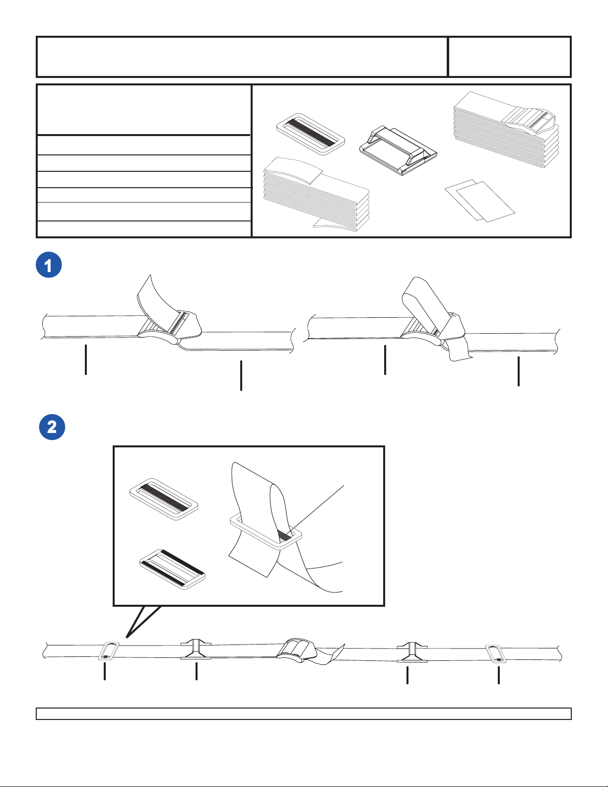
Begin by connecting belt with buckle (C) to belt without buckle (D).
Model: ACC 316
C
B
E
D
Some parts may appear slightly different than illustrated.
C
D
Continue by sliding on one belt guide (B) and one tri-bar belt clip (A) on each side of the buckle. Refer to drawing
below.
TOP
NOTE LINES
FACES UP
C
D
A
BOTTOM
A
Visit the Peerless Web Site at www.peerlessmounts.com For customer care call 1-800-729-0307 or 708-865-8870.
B
1 of 4
B
ISSUED: 01-30-07 SHEET #: 009-9037-1
A
Page 2
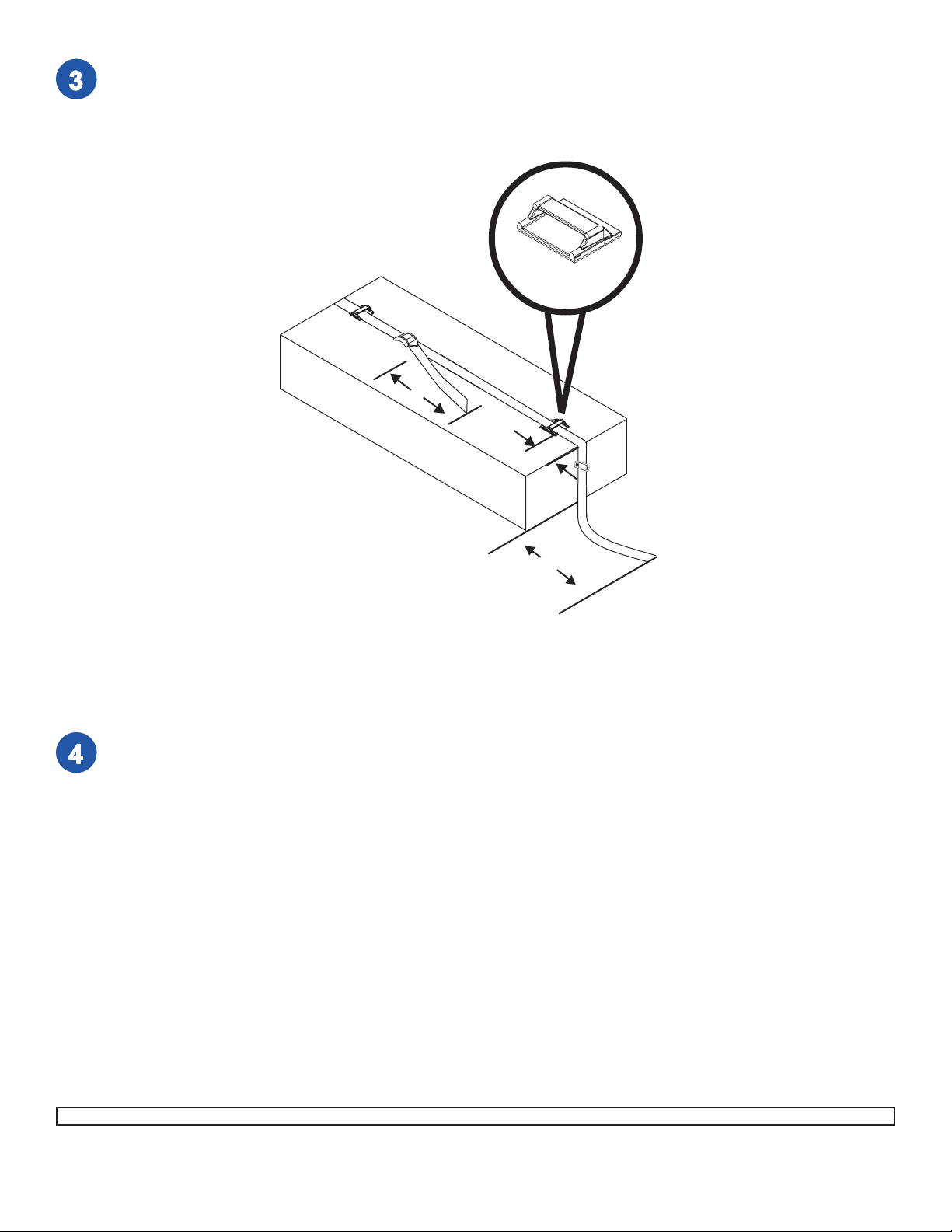
With the electronic component dismounted, place belt assembly over electronic component and reposition the
components according to dimensions in drawing below . Note: keep buckle closer to left side of the electronic
component to allow for movement when tightening belt assembly . T rim off the end of the belt if necessary , then lightly
burn the end of the belt to prevent fraying. Repeat step 3 for the other side of the electronic component.
B
electronic component
6”
2”
A
12”
Make sure that electronic component surface is clean of grease, oil and dust. Once all components are in place,
remove sticker from bottom of belt guides and firmly press them onto the electronic component.
2 of 4
Visit the Peerless Web Site at www.peerlessmounts.com For customer care call 1-800-729-0307 or 708-865-8870.
ISSUED: 01-30-07 SHEET #: 009-9037-1
Page 3

Select slot in tray according to diagram 5.1.
Remove backing and attach one clear strip (E)
through slot and around edge of tray as pictured
in diagram 5.2. Repeat for other slot in other side
of tray .
Note: This material prevents fraying or cutting of
the belt.
Place electronic component onto tray .
Note: Be sure that front bottom edge of electronic
component is positioned behind and against the
front lip of the tray . This will prevent electronic
component from sliding forward on the tray .
DIAGRAM
5.1
TRA Y
FRONT LIP
ELECTRONIC COMPONENT NOT SHOWN
DIAGRAM
5.2
ELECTRONIC COMPONENT NOT SHOWN
BEL T SLOTS
electronic component
E
Take one belt (C or D) and hold it so that the tri-bar belt clip (A) is facing as illustrated. Feed belt (C or D)
up through the slot you have chosen. Remember, belt only goes through out side slot. Now feed belt (C or
D) through belt clip (A) as shown. Repeat on other side of tray using other belt.
ELECTRONIC COMPONENT NOT SHOWN
A
TIGHTEN
C or D
3 of 4
Visit the Peerless Web Site at www.peerlessmounts.com For customer care call 1-800-729-0307 or 708-865-8870.
ISSUED: 01-30-07 SHEET #: 009-9037-1
Page 4

WARNING
• The safety belt provided with your mount is designed to stabilize the electronic component on the mounting tray.
• It is the responsibility of the installer to ensure the stability of the television by purposefully pushing the electronic
component in all directions to test the installation.
Tighten belt by pulling on loose end.
LOOSE END
4 of 4
Visit the Peerless Web Site at www.peerlessmounts.com For customer care call 1-800-729-0307 or 708-865-8870.
ISSUED: 01-30-07 SHEET #: 009-9037-1
 Loading...