

Page 1
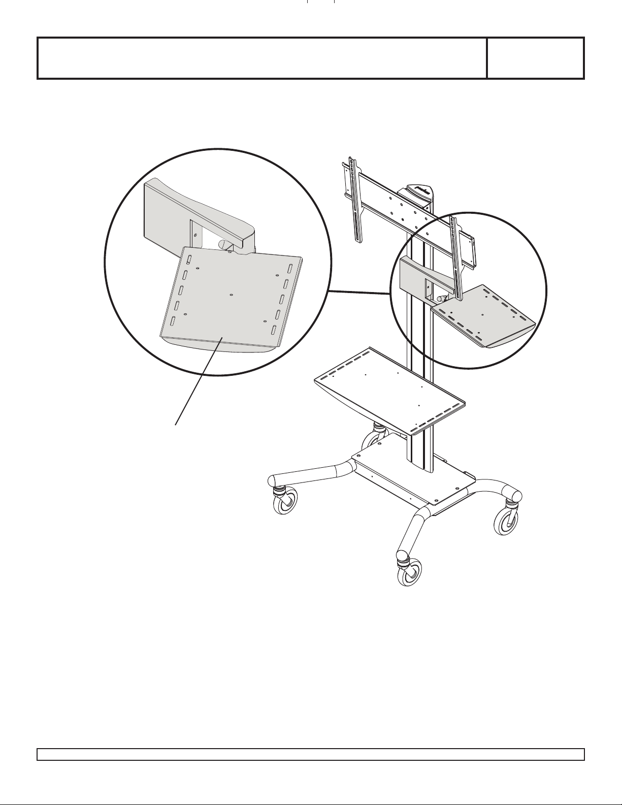
Installation and Assembly: Laptop Arm
IMPORTANT! Read entire instruction sheet before you start assembly and installation.
Some parts may appear slightly different than illustrated.
Model: ACC314
LAPTOP ARM
1 of 3
Visit the Peerless Web Site at www.peerlessmounts.com For customer care call 1-800-729-0307 or 708-865-8870.
ISSUED: 01-25-07 SHEET NO: 009-9035-2 01-18-11
Page 2
A
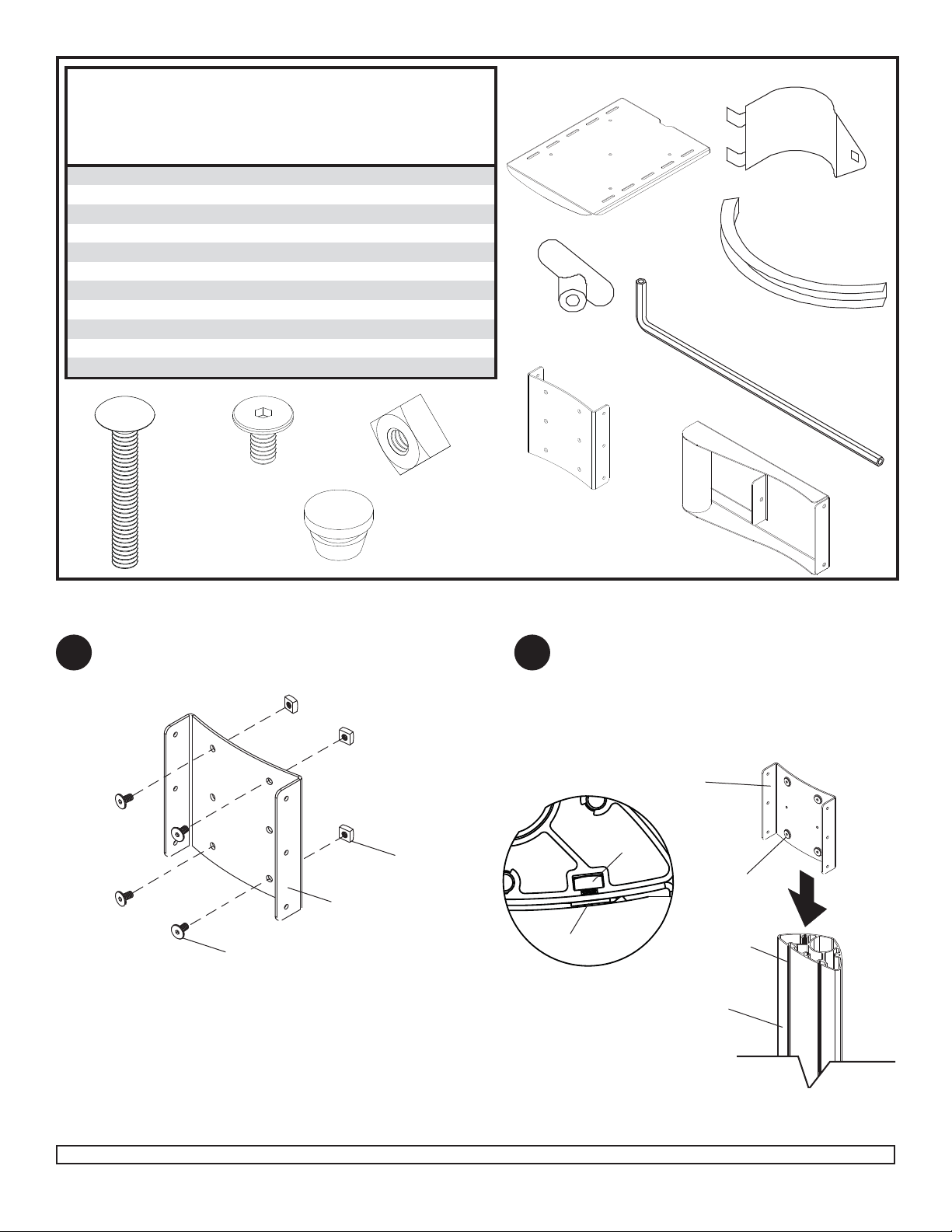
Before you begin, make sure all parts shown are included
with your product.
B
Parts List
Description Qty. Part #
laptop tray 1 009-1227
B laptop tray clamp 1 009-1020
C T-knob 1 590-1057
D 1/4" - 20 x 1 3/4" carriage bolt 1 520-1017
E plastic grommet 2 590-1074
F screen mount bracket 1 201-1156
G shelf support 1 009-1230
H 1/4 x 12 mm decorative screw 7 520-2325
I 1/4 - 20 mm square nut 4 530-1050
K button bumper 5 590-1209
L allen wrench 1 560-9646
HD
I
K
A
E
C
L
F
G
NOTE: If you are adding new shelf to an already assembled product, reverse steps up to the shelf installation step
(removing screen and adapter plate from cart) following the main instruction sheet.
Loosely attach four 1/4-20 x 12mm screws (H) and
1 2
1/4-20 nuts (I) to screen mount bracket (F).
Slide screen mount bracket (F) onto upright so
that 1/4-20 nuts (I) slide into slots of upright as
shown in fi gure 2.1 and detail 1. Slide screen
mount bracket to desired position, level, then
tighten 1/4-20 x 12mm screws (H) using 4mm
allen wrench (L).
F
I
I
H
F
H
H
DETAIL 1
UPRIGHT
SLOT
fi g 2.1
2 of 3
Visit the Peerless Web Site at www.peerlessmounts.com For customer care call 1-800-729-0307 or 708-865-8870.
ISSUED: 01-25-07 SHEET NO: 009-9035-2 01-18-11
Page 3

Attach self support (G) to screen bracket bracket (F) as shown in fi g. 3.1. Insert three 1/4-20 x 12 mm screws (H)
1/8"
3
into screen mount bracket (F), leaving 1/8" of exposed thread as shown in fi g. 3.2 and detail 2.
F
G
fi g 3.1
Attach two grommets (E) to back of laptop tray
4 5
(A), and attach fi ve button bumper (K) to the top of
laptop tray (A) as shown below.
H
DETAIL 2
fi g 3.2
Attach laptop tray (A) to shelf support (G) using
clamp (B), carriage bolt (D) and T-knob (C).
Hook tabs of clamp (A) into slots of laptop tray
(A) as shown in fi g. 5.1, then secure clamp and
tray around shelf using carriage bolt (D) and
T-knob (C) as shown fi g. 5.2.
B
E
A
C
D
T-KNOB
A
CLAMP
fi g 5.1 fi g 5.2
3 of 3
Visit the Peerless Web Site at www.peerlessmounts.com For customer care call 1-800-729-0307 or 708-865-8870.
© 2011 Peerless Industries, Inc. All rights reserved.
Peerless is a registered trademark of Peerless Industries, Inc.
ISSUED: 01-25-07 SHEET NO: 009-9035-2 01-18-11
CARRIAGE
BOLT
 Loading...