

Page 1
Installation and Assembly - Concrete fasteners
Fastener Kit Per Anchor Per Kit Per Anchor Per Kit
ACC233 250 lb (113.4 kg) 750 lb (340.2 kg) 250 lb (113.4 kg) 750 lb (340.2 kg)
ACC234 250 lb (113.4 kg)
1000 lb (453.6 kg)
250 lb (113.4 kg)
1000 lb (453.6 kg)
ACC230 250 lb (113.4 kg) - 250 lb (113.4 kg) ACC243 475 lb (215.5 kg) 1425 lb (646.4 kg) 475 lb (215.5 kg) 1425 lb (646.4 kg)
ACC244 475 lb (215.5 kg) 1900 lb (861.8 kg) 475 lb (215.5 kg) 1900 lb (861.8 kg)
A
CC240 475 lb (215.5 kg
)
- 475 lb (215.5 kg
)
-
Max. Load Concret
e
Max. Load Cinder Bloc
k
Part
#
Qty. Description
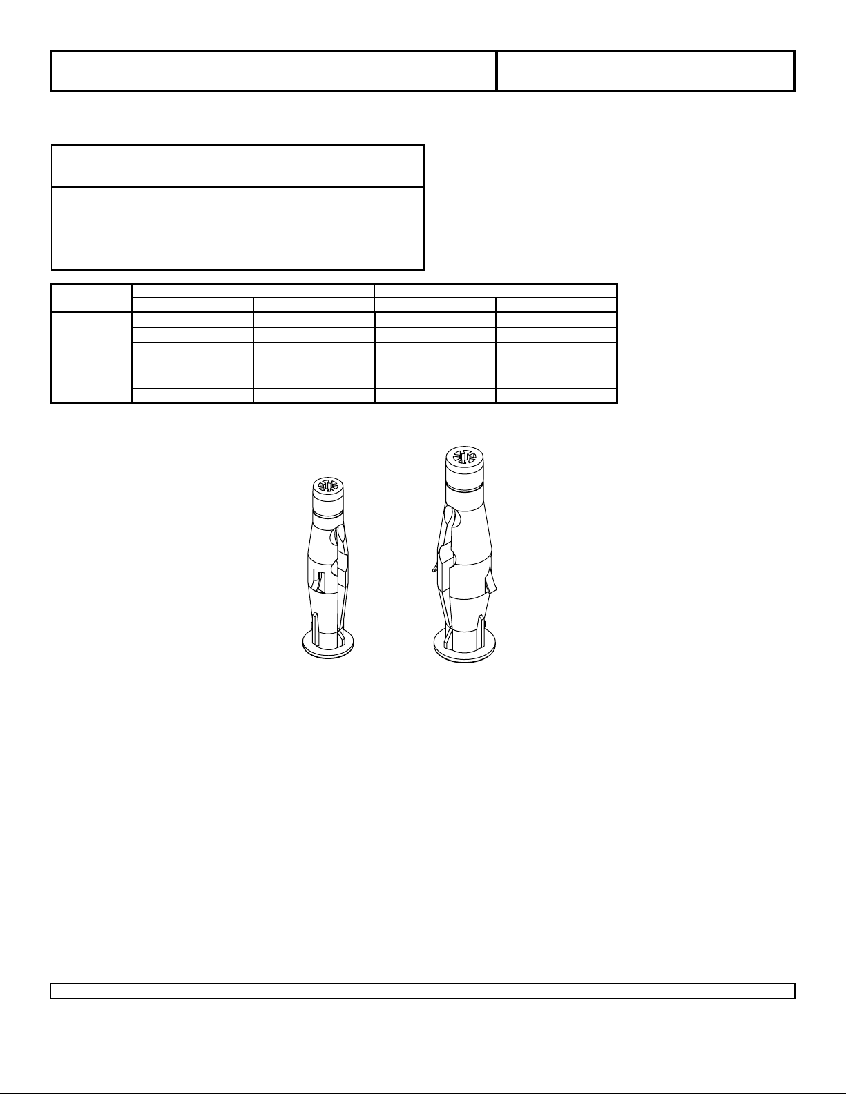
A 590-0320 3 8 mm concrete anchors (ACC233 only)
4 8 mm concrete anchors (ACC234 only)
50 8 mm concrete anchors (ACC230 only)
590-0321 3 10 mm concrete anchors (ACC243 only)
4 10 mm concrete anchors (ACC244 only)
50
10 mm concrete anchors
(
ACC240 only)
Parts List
NOTE: Read entire instruction sheet before you start installation and assembly.
Before you start make sure all parts listed are included with your product.
* *
* Cumulative maximum load rating is based on the use of all fasteners included
Model: ACC233, ACC234, ACC230,
ACC243, ACC244, ACC240
8 mm
A
10 mm
Visit the Peerless Web Site at www.peerlessindustries.com For customer service call 1-800-729-0307 or 708-865-8870.
1 of 2
ISSUED: 08-05-09 SHEET #: 120-9069-1
Page 2
WARNING
• When installing Peerless wall mounts on cinder block, verify that you have a minimum of 1-3/8" (35 mm) of actual
concrete thickness in the hole to be used for the concrete anchors. Do not drill into mortar joints! Be sure to mount
in a solid part of the block, generally 1" (25 mm) minimum from the side of the block. Cinder block must meet ASTM
C-90 specications. It is suggested that a standard electric drill on slow setting is used to drill the hole instead of a
hammer drill to avoid breaking out the back of the hole when entering a void or cavity.
• Concrete must be 2000 psi density minimum. Lighter density concrete may not hold concrete anchor.
• Make sure that the wall will safely support four times the combined load of the equipment and all attached hardware
and components.
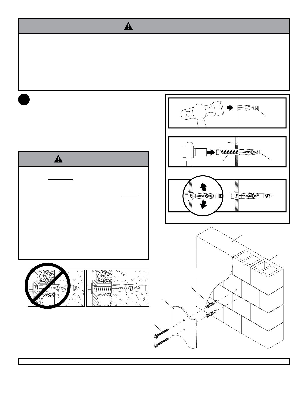
Use wall plate as a template, level wall mount and
1
mark center of mounting holes. If using 8 mm concrete
anchors, drill 5/16" (8 mm) dia. holes to a minimum
depth of 2.5" (64 mm). If using 10 mm concrete anchors,
drill 13/32" (10 mm) dia. holes to a minimum depth of
3" (76 mm). Insert anchors (A) in holes ush with wall,
place wall mount over anchors and secure with wood
screws as shown right. Make sure wall mount is level,
and tighten all fasteners.
1
Drill holes and insert anchors (A).
2
wall plate
concrete
surface
A
WARNING
• Tighten screws so that wall plate is rmly attached,
but do not overtighten. Overtightening can damage
screws, greatly reducing their holding power.
• Never tighten in excess of 80 in. • lb (9 N.M.).
• Always attach concrete expansion anchors directly to
load-bearing concrete.
• Never attach concrete expansion anchors to concrete
covered with plaster, drywall, or other nishing mate-
rial. If mounting to concrete surfaces covered with a
nishing surface is unavoidable, the nishing surface
must be counterbored as shown below. Be sure concrete anchors do not pull away from concrete when
tightening screws. If plaster/drywall is thicker than
5/8" (16 mm), custom fasteners must be supplied by
installer.
INCORRECT CORRECT
plate
CUTAWAY VIEW
wall
plaster/
dry wall
concrete
wall
plate
plaster/
dry wall
concrete
wood screw
Place plate over anchors (A) and secure with wood screws.
3
Tighten all fasteners.
concrete
A
mounting
plate
A
cinder block
wood screws (not included)
2 of 2
Visit the Peerless Web Site at www.peerlessindustries.com For customer service call 1-800-729-0307 or 708-865-8870.
© 2007, Peerless Industries, Inc. All rights reserved.
All other brand and product names are trademarks or registered trademarks of their respective owners.
ISSUED: 08-05-09 SHEET #: 120-9069-1
 Loading...