

Page 1
Installation and Assembly - Internal Joist Mount
Model: ACC 120
IMPORT ANT! Read entire instruction sheet
before beginning installation and assembly .
MAXIMUM LOAD CAPACITY : 300 lb (137 kg)
Maximum Load capacity refers to the combined
load of all attached equipment and hardware.
C
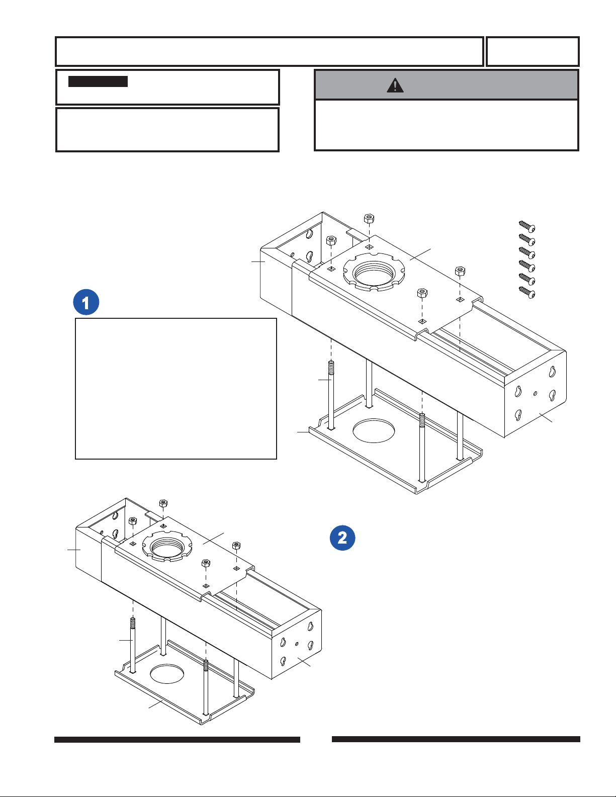
Check parts list to ensure that
all parts have been included.
PARTS LIST
PART # QTY. DESCRIPTION
A 500-9006 6 #10 x 3/4" phillips screw
B 092-1005 1 upper clamping bracket
C 092-1001 1 extension bracket - left
D 092-1001 1 extension bracket - right
E 530-9413 4 1/4-20 nylock nut
F 520-9556 4 1/4-20 x 3.75" carriage bolt
G 092-1007 1 lower clamping bracket
H 520-9250 1 M5 x .8 x 10 mm phillips screw
(for use with EXT models)
Parts may appear slightly different than illustrated.
G
WARNING
• Installer must verify that the ceiling will safely support
four times the combined weight of all attached equipment and hardware.
E
A
B
F
D
C
F
G
E
B
Assemble as shown.
IMPORTANT: If installer is working above the
ceiling, such as in an attic space, assemble
exactly as pictured. If installer is working below
the ceiling, reverse positions of carriage bolts (F)
and nylock nuts (E).
Tighten 1/4-20 nylock nuts (E) just enough to
allow for expansion / compression of extension
brackets (C & D).
D
1 of 2
ISSUED: 6-12-97 SHEET #: 092-9001-3 08-24-12
Page 2
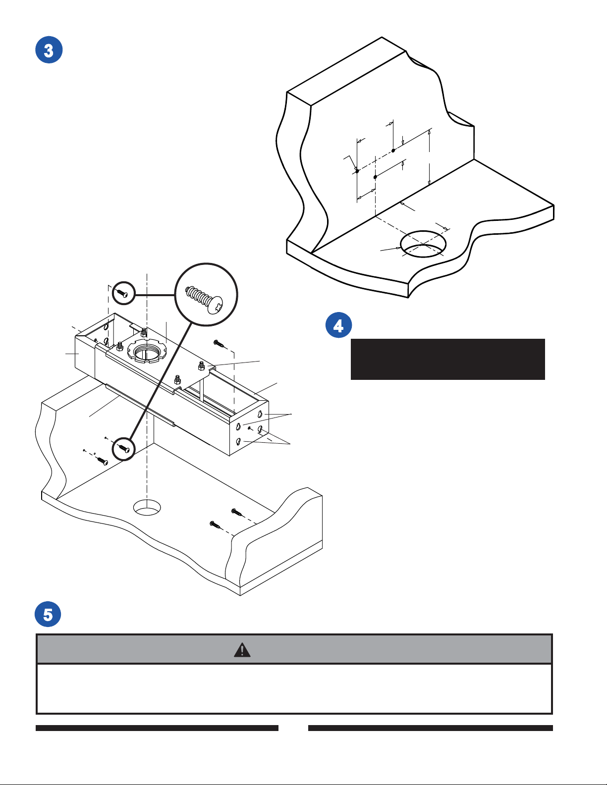
Drill three 1/8" dia. holes 3/4" deep into inside
edge of each ceiling joist. Dimensions for locating holes are pictured. If installing an extension
column (not included) through a finished ceiling,
a 2" dia. hole can be located anywhere along
centerline, but it must be at least 2 3/4" away
from right or left stud.
joist
1/8" dia.
1 1/8"
2 1/4"
2" dia.
centerline
5/8
2 1/4" min.
2 3/4" min.
C
G
B
A
E
D
upper keyslots
DO NOT USE!
ceiling
If applicable, drill 2" dia. hole through finished
ceiling at the desired location.
Remember that the hole will have to
align exactly with the hole in the lower
clamping bracket (G).
Insert four #10 x 3/4" phillips screws (A), two
into each ceiling joist. Leave just enough
exposed thread to engage with upper keyslots
in ends of extension brackets (C & D).
Compress extension brackets just enough to
clear the heads of the four screws. Expand &
engage UPPER KEYSLOTS (lower keyslots
not to be used) over heads of screws. An offset
screwdriver may be required. Insert two
remaining #10 x 3/4" phillips screws (A), one
through each center hole in each extension
bracket (C & D). Securely tighten all six
screws.
Slide clamping bracket assembly to desired
position (in alignment with hole in finished
ceiling, if applicable). Tighten all four 1/4-20
nylock nuts (E) securely.
To install extension column insert through lower clamping bracket (G) into threaded fitting in upper clamping
bracket (B). Tighten four or five complete turns until securely tight.
WARNING
• For added safety , threaded fitting is treated with a special bonding agent that will be activated when extension
column is attached. If extension column is removed at a later time bond will be rendered ineffective. In such
cases, bonding agent such as Loctite® should be applied to threads before extension column is reattached.
© 2012 Peerless Industries, Inc. All rights reserved.
Peerless is a registered trademark of Peerless Industries, Inc.
All other brand and product names are trademarks or registered trademarks of their respective owners.
2 of 2
ISSUED: 6-12-97 SHEET #: 092-9001-3 08-24-12
 Loading...