

PEERLESS SERIES 62, 61 Series, 61-03, 61-04, 61-05 Installation, Operation & Maintenance Manual
...Page 1
61/62
Boilers
Installation,
Operation Et
Maintenance
Manual
Page 2

3-8 90,0 Up to 81.7% AFUE
Natural or LP Gas
Standing Pilot (Steam Only) or Spark Ignition (Hot Water and Steam)
Natural Draft (chimney) Venting
Factory Assembled Sections on Knockdown Boilers
• Reduces Installation Time
Large Water Content
• Ideal for Steam and Large Volume Hot Water Applications
Skim Tapping
• For Cleaning Steam Boilers
Low Profile Design
• Horizontal to Vertical Draft Diverter
• Ideal for Installations with Low Ceilings
Steel Push Nipples
• Provide a Permanent Water Tight Seal Between Sections
• Unaffected by Petroleum and Other Contaminants
Tankless Coils
• For Domestic Hot Water Production on Hot Water Boilers
Deluxe Insulated Enameled Steel Jacket
• Reduces Boiler Heat Loss
• Completely Encloses Gas Valve and Burners
Safety Controls
• Low Water Cut-Offon Steam Boilers
• Flame Roll-Out Shut-OffSwitch
• Blocked Vent Shut-OffSwitch
• Honeywell Operating Controls
• Vent Damper
• Float Type LWCO on Steam Boilers
• Taco 007 Circulator on Packaged Water Boilers
• Tankless Coil for Hot Water Boilers
• Gnmdfos Circulator on Packaged Hot Water Boilers
• Probe Type LWCO on Steam Boilers
Peerless Heater Comparly is pleased to offer one of the most comprehensive warranty programs
icl tile indnstn 1, All Peerless residential cast troll _x_ilers include a fidl one-yea" warranty. A limited.
lifetone warranty is provided.for the cast iron sections ol Peerless residential hot water boilers.
Peerless also provides a limited, ten year warranty ot_ the cast iron sections of its residential steam
boilers. Five and ten year extended warratlties on parts and labor are now available. Pl_'asc consult
Peerl_,ss Heater Company for complete warranty inJbrmation.
PGGRLESS _
CAST IRON BOILERS
Peerless Heater Company * 231 North Walnut Street • Boyertown, PA 19512-1021 • 610-3S7-2153 * www.peerless-heater.eom
FAB-61 R1 (3/02 3M)
Printed in US A
Page 3
pr=-I RLESS o
CAST IRON BOILERS
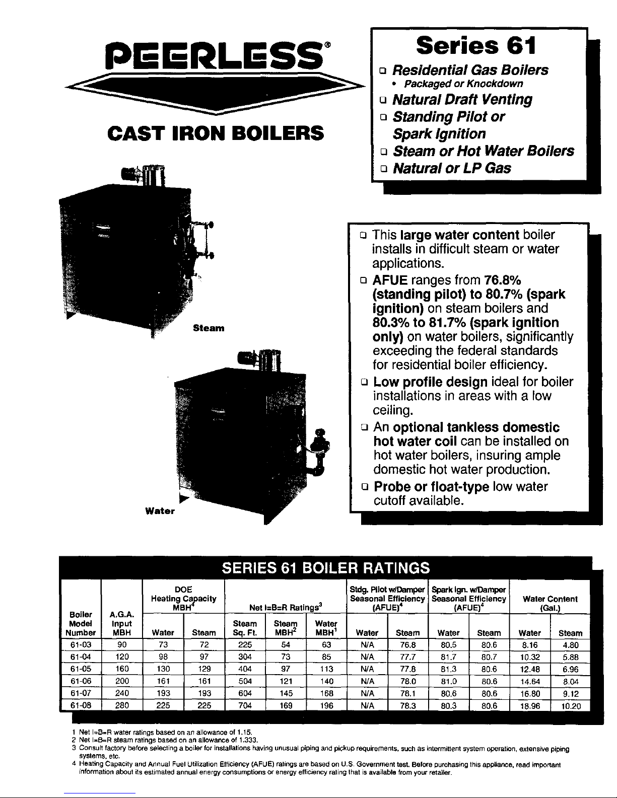
Series 61
o Residential Gas Boilers
• Packaged or Knockdown
o Natural Draft Venting
o Standing Pilot or
Spark Ignition
Q Steam or Hot Water Boilers
o Natural or LP Gas
Water
Steam
Q This large water content boiler
installsindifficultsteam or water
applications.
o AFUE ranges from 76.8%
(standing pilot) to 80.7% (spark
ignition) on steam boilers and
80,3% to 81.7% (spark ignition
only) on water boilers, significantly
exceeding the federal standards
for residential boiler efficiency.
o Low profile design ideal for boiler
installationsin areas with a low
ceiling.
An optional tankless domestic
hot water coil can be installed on
hotwater boilers, insuringample
domestichotwater production.
o Probe or float-type lowwater
cutoff available.
DOE
Heating Capacity
MBH--
Stdg.PilotwlDamper
Seasonal Efficiency
(AFUE)4
Net I=B=R Ratings 3
Steam Steam Water
Sq. Ft. MBH 2 MBH 1
225 54 63
304 73 85
4O4 97 113
504 121 140
604 145 168
704 169 196
Spark Ign. wlDamper
Seasonal Efficiency
(AFUE) 4
Water Content
(GaL)
I A,G.A.
I Input
N MBH Water Steam Water I Steam Water I Steam Water Steam
90 73 72 N/A I 76.8 80.5 I 80.6 8.16 4.80
120 98 97 N/A I 77.7 81.7 I 80.7 10.32 5.88
160 130 129 N/A I 77,8 81.3 I 80.6 12.48 6.96
200 I 161 161 N/A I 78.0 81.0 I 80.6 14.64 8.04
240 193 193 N/A I 78.1 80.6 I 80.6 16.80 9.12
280 225 225 N/A I 78.3 80.3 I 80.6 18.96 18.20
1 Net I=B=R water ratings based on an allowance of 1.15,
2 Net I=B=R steam ratings based on an allowance of 1.333.
3 Consult factory before selecting a boiler for installations having unusual piping and pickup requirements, such as intermittent system operation, extensive piping
systems, etc.
4 Heating Capacity and Annual Fuel Utilization Efficiency (AFUE) ratings are based on U.S. Government test. Before purchasing this appliance, read important
information about its estimated annual energy consumptions or energy efficiency rating that is available from your retailer.
Page 4

7 Sizes 9-15 Sections
320 to 560 MBH Input 80% Combustion Efficiency
Natural or LP Gas
Standing Pilot or Spark Ignition
Natural Draft (chimney) Venting
Factory Assembled Sp/it Block Sections on Knockdown Boilers
• For Ease of Handling
Large Water Content
• Ideal for Steam and Large Volume Hot Water Jobs
Skim Tapping
• For Cleaning Steam Boilers
Low Profile Design
• Horizontal to Vertical Draft Diverter
• Idealfor Installatiolis with Low Ceilings
Steel Push Nipples
• Provide a Permal_ent Water Tight Seal Between S_ctioris
• Unaffected by Petroleum arid Other Cor_tamiTlalltS
Tankless Coils
• For Domestic Hot Water Production o_ Hot Water Boilers
Deluxe Insulated Enameled Steel Jacket
• Reduces Boiler Heat Loss
• Completely Encloses Gas Valve and Burners
Safety Controls
• Low Water Ctlt Q[l'orl Steam Boil_'rs
• HoT_eywell Operating Co_ltrols
• Mar_ltal Reset High Limit Corltrol (12-15 Section)
• Float Type LWCO orl Steam Boilers
• Tcxl_lcless Coiljor Hol Watcr Boilers
• Moclultxtillg Fi1_rlg Systems (12 15 S<:cliorl}
• F_'I _rid IRI Colltrol S!]slerTls (12 15 Sectioll)
• Prot)t> "I_upe I.WCO o11Sle(lfll Boilers
_ll lilt" il_(lll._lr'!]. ./Ill I_'_'r'l( '.,_.s ('ollilll_'r('i(¢l _'cl.'q/ _rt)ll I)oih>l_ _ll_'h_(l_ >(I /illl. oil(' ! (>_'lr" tl,_ls't(_ll[ 1. A
lilliilt>(I. It'll !]('(1I II'_llltll_l[/ I)ll I]l(" _'tl._l il'oll ._('t'l_oll._ i.'_ [)l()l'l_ll'_ [i_t (ill ( Ollllll<'F('i_ll 11(>I I_ll('I _lll([
,'_l_>(llll I?l_il(>I'_. I+'il'( ' _lll_'l [I'll I I>tlr ('._l_'tl_l(>_l ll'_l_'ltlllll_'_ I)ll l_(It l_ (lll_l I_l!)ol (It't' /loll' ttl'(li[(l!)_('. CAST IRON BOILERS
!'lt>(_._;( ' €'otl.'_ll/I I>_'('t'l_ '.'q_ I h'_ll_'t ( "olllt)_lltt].[O_" _'Oml)lt'f_" it,t_r_t_i_l!] ir!]Oi rIl(llioll.
Peerless Heater Company • 231 North Walnut Street * Boyertown. PA 19512 1021 • 610 367-2153 - www.peerless-heater.com
FAB 6_7t9 02 :_,%
Page 5
pGr=-RLESS o
CAST IRON BOILERS
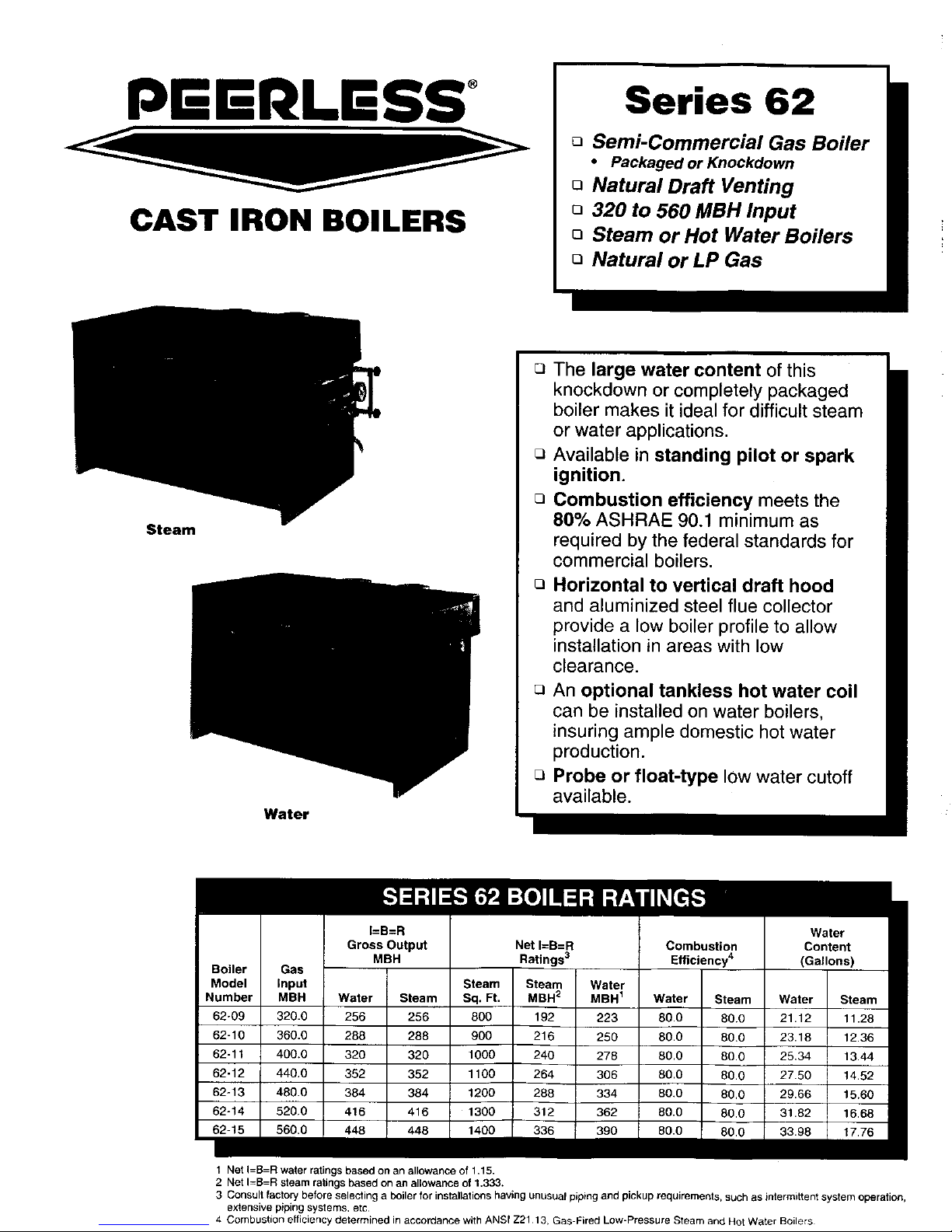
Series 62
o Semi-Commercial Gas Boiler
• Packaged or Knockdown
o Natural Draft Venting
o 320 to 560 MBH Input
o Steam or Hot Water Boilers
o Natural or LP Gas
Steam
Water
o The large water content of this
knockdown or completely packaged
boiler makes it ideal for difficult steam
or water applications.
o Available in standing pilot or spark
ignition.
o Combustion efficiency meets the
80% ASHRAE 90.1 minimum as
required by the federal standards for
commercial boilers.
O
Horizontal to vertical draft hood
and aluminized steel flue collector
provide a low boiler profile to allow
installation in areas with low
clearance.
r_ An optional tankless hot water coil
can be installed on water boilers,
insuring ample domestic hot water
production.
o Probe or float-type low water cutoff
available.
I=B=R Water
Gross Output Net I=B=R Combustion Content
MBH Ratings 3 Efficiency 4 (Gallons)
Model Input Steam Steam Water
Number MBH Water Steam Sq. Ft. MBH2 MBH 1 Water Steam Water Steam
62-09 320.0 256 256 800 192 223 80.0 80.0 21.12 11.28
62-10 360.0 288 288 900 216 250 80.0 80.0 23.18 12.36
62-11 400.0 320 320 1000 240 278 80.0 80.0 25,34 13.44
62-12 440,0 352 352 1100 264 306 80.0 80.0 27.50 14.52
62-13 480.0 384 384 1200 288 334 80.0 80.0 29.66 15.60
62o14 520.0 416 416 1300 312 362 80.0 80.0 31.82 16.68
1 Net I=B=R water ratings based on an allowance 011.15.
2 Net I=B=R steam ratings based on an allowance of 1.333.
3 Consult factory before selecting a boiler for installations having unusual piping and pickup requirements, such as intermittent system operation,
extensive piping systems, etc
4 Combustion efficiency determined in accordance with ANSf Z21 13, Gas-Fired Low-Pressure Steam and Hot Water Boilers
Page 6
I
J
K
L
M
N
O
P
Q
R
m
Boiler
Model
Number
62-09
62-10
62-11
62-12
62-13
62-14
62-15
Steam Water
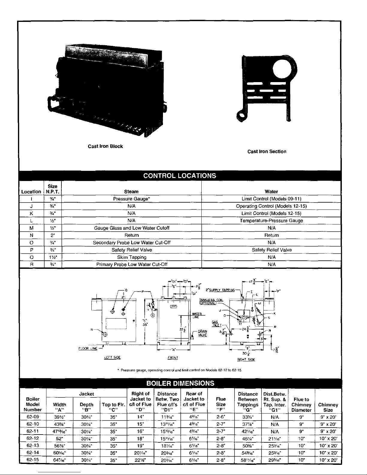
3/4" Pressure Gauge* Limit Control (Models 09-11)
3/4,, N/A Operating Control (Models 12-15)
3/4" N/A Limit Control (Models 12-15)
V2" N/A Temperature-Pressure Gauge
V2" Gauge Glass and Low Water Cutoff N/A
2" Return Return
3/4" Secondary Probe Low Water Cut-Off N/A
3/4" Safety Relief Valve Safety Relief Valve
1V2" Skim Tapping N/A
¾" Primary Probe Low Water Cut-Off N/A
3o4-
L£_'T SID_ £RON_ RIGH T SIDE
• Pressure gauge, operating control and I_mitcontrol on Models 62 12 to 62 15
Jacket Right of Distance Rear of Distance , . .
Jacketto Betw. Two Jacketto Flue Between !Rt. Sup.& C_uetOy
Width Depth Top to Fir. c/I of Flue Flue c/l's c/I of Flue Size Tappings Tap. Inter. Chimney
"A .... B.... C.... D.... D1 .... E.... F.... G.... GI"
39V2" 30V4" 35" 14" 11%#' 4%s" 2-6" 333/." N/A 9" 9" x 20'
43%" 30V4" 35" 15" 13_V_6" 4%8" 2-7" 37%" N/A 9" 9" x 20'
47_¾_' 30V4" 35" 16" 15_3/lS" 4%4' 2-7" 42V16" N/A 9" 9" x 20'
52" 30V4" 35" 18" 15_%#' 6_/_6" 2-8" 46V4" 21_/_6" 10" 10" x 20'
56Ys" 30V4" 35" 19" 18V_6" 6Vls" 2-8" 50%" 253/16" 10" 10" x 20'
60%6" 30_/4" 35" 20VI4' 20¾e" 6V_6" 2-8" 54%6" 25z/_6" 10" 10" x 20'
64W_6" 30V4" 35" 22W' 203Ae" 6%6" 2-8" 58"A_" 29s/_6" 10" 10" x 20'
Page 7
STEAM WATER
, , i
t t
"L
Boiler
Model
Number
62-09
62-10
62-11
62-12
62-13
62-14
62-15
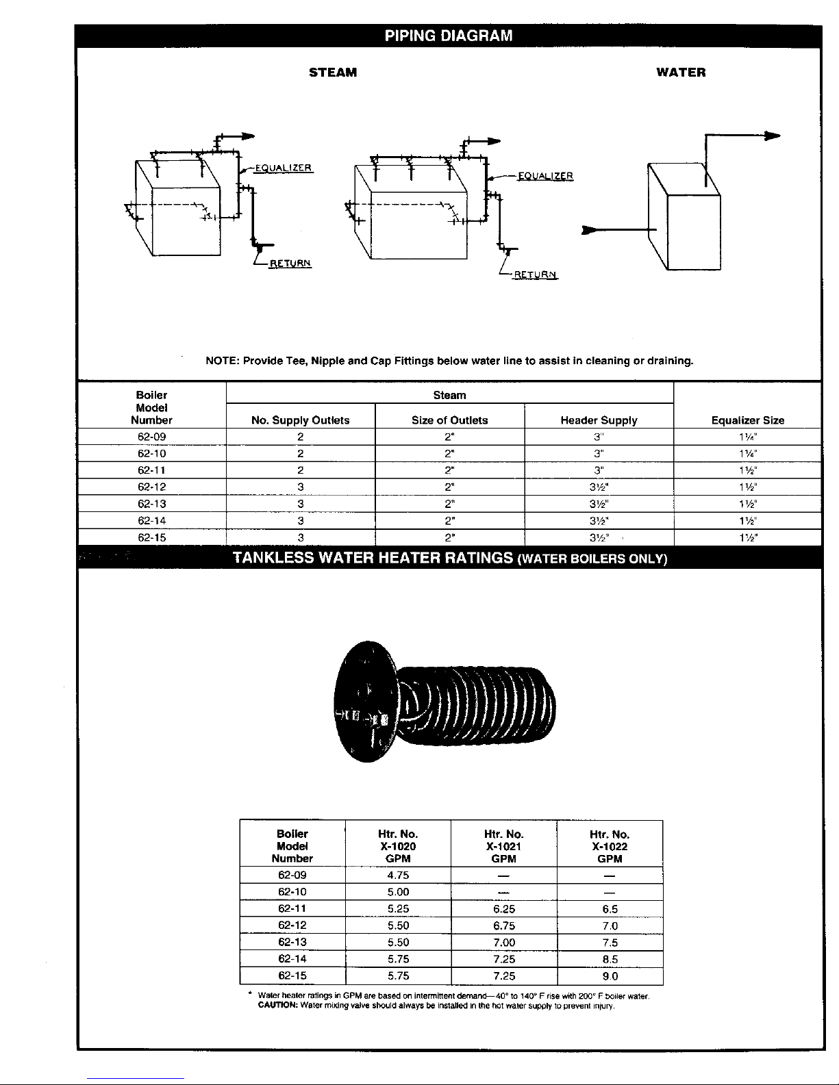
NOTE: Provide Tee, Nipple and Cap Fittings below water line to assist in cleaning or draining.
Steam
No. Supply Outlets
2
2
2
3
3
3
3
Size of Outlets
2"
2"
2"
2"
2"
2"
Header Supply
3 _=
3"
3"
3V2"
31/2''
31/2'`
31/2" ,
Equalizer Size
1V4"
11/4"
1V2"
1V2"
1V2"
1W'
1V2"
Boiler
Model
Number
62-09
62-10
62-11
62-12
62-13
62-14
62-15
Htr. No.
X-1020
GPM
4,75
5.00
5.25
5.50
5.50
5.75
5.75
Htr. No. Htr. No.
X-1021 X-1022
GPM GPM
6.25
6.75
7.00
7.25
7.25
m
6.5
7.0
7.5
8.5
9.0
* Water healer ratings in GPM are based on intermittent demand40 ° to 140 _ F rise with 200 ° F bOiler water
CAUTION: Water mixing valve should always be installed in the hot water supply to prevent injury,
Page 8
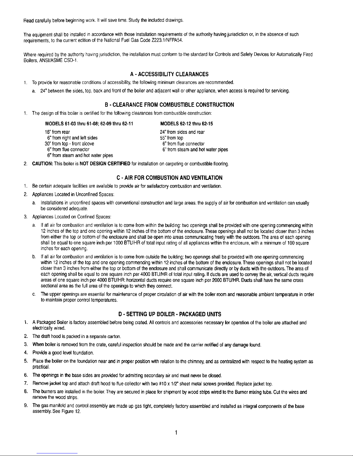
SERIES 62 BOILER SPECS
_-_-_ LlJl-J_vd_id
• Cast Iron Sections--Factory Tested and
Assembled with Steel Push Nipples
• Deluxe Insulated Enameled Steel Jacket
• Drain Valve
• Horizontal to Vertical Draft Diverter
• End Cleanout
• Manual Reset Limit (62-12 to 62-15)
• Standing Pilot or Spark Ignition
• Automatic Reset Limit
Water
• 30 PSI Safety Relief Valve
• Temperature-Pressure Gauge
Steam
• 15 PSI Safety Valve
• Pressure Gauge
• Gauge Glass
• Low Water Cutoff - Probe or Float
• Skim Tapping
• HSP-2 Honeywell ignitionSystem
• 50 PSI Safety Relief Valve - Water Boilers
• Insurance Controls
• I.R.I.
,F.M.
• Ignition Systems
• HSP-2
• E1-M
• E1-E
• Modulating Firing Systems
• MFSC
• Mod-U-Pak (12-15 Section)
Approx. Shipping Wts. (Ibs.)
Boiler
Model
Number I Length I Width ! Height I W S
I I I !
62-09 I 57" 31" I 391/2" I 1080 I 1088
I I I I
62-10 I 61" 3t" J 391/2" J 1170 I 1178
I I I I
62-11 I 66" 31" I 391/2`' ! 1265 I 1273
I I I ]
62-12 I 70" 31" I 391/2" ] 1420 I 1428
I I I !
62-13 I 74" 31" I 391/2" I 1520 I 1528
I I I J
62-14 I 78" 31" I 391/2'' ] 1620 I 1628
I I I I
62-15 I 82" 31" I 391/2" I 1720 1 1728
WP SP
1105 1108
1195 1203
1290 1298
1445 1453
1545 1553
1645 1653
1745 1753
nnam
Example:
62 - 09 - STDG/SPRK - WP - N
Series Sects. Natural Gas (Substitute
Standing Pilot or "LP" for LP Gas)
Spark Ignition W = Water Knockdown
WP = Water Package
S = Steam Knockdown
SP = Steam Package
PEERLESSHEATERCO.
231 North Walnut Street
Boyertown, PA 19512-1021
Phone: 610-367-2153 • FAX: 610-369-3284
www.peerless-heater.com
HI Division ASME garNa
of gama
CUT-62 F_7(3/03-1M), Printed in U SA. _003 Peedess Heater Company
Page 9
Readcarefullybeforebeginningwork.It witlsavetime.Studythe includeddrawings.
Theequipmentshallbe installedin accordancewith thoseinstallationrequirementsofthe authorityhavingjurisdictionor, in theabsenceof such
requirements,to thecurrenteditionof the NationalFuelGas CodeZ223.1/NFPA54.
Whererequiredbythe authorityhavingjurisdiction,theinstallationmustconformto the standardforControlsand SafetyDevicesforAutomaticallyFired
Boilers,ANSI/ASMECSD-I.
A - ACCESSIBILITY CLEARANCES
1. Toprovidefor reasonableconditionsofaccessibility,the followingminimumclearancesarerecommended.
a. 24" betweenthesides,top,backandfrontof theboilerand adjacentwallor otherappliance,whenaccessis requiredforservicing.
B- CLEARANCEFROMCOMBUSTIBLECONSTRUCTION
1. Thedesignofthisbelieriscertifiedforthefollowingclearancesfromcombustibleconstruction:
MODELS61-03thru61-08;62-09thru 62-11
18"fromrear
6"from rightand left sides
30"fromtop- frontalcove
6"fromflue connector
6"from steamandhot waterpipes
MODELS62-12thru62-15
24"fromsidesand rear
55"fromtop
6"fromflueconnector
6"fromsteamandhotwaterpipes
2. CAUTION:This boileris NOTDESIGNCERTIFIEDforinstallationon carpetingor combustibleflooring.
C-AIR FORCOMBUSTIONANDVENTILATION
1. Be certainadequatefacilitiesareavailableto provideairforsatisfactorycombustionandventilation.
2. AppliancesLocatedin UnconfinedSpaces:
a. Installationsin unconfinedspaceswithconventionalconstructionandlarge areas:thesupplyofairfor combustionandventilationcanusually
beconsideredadequate,
3, AppliancesLocatedonConfinedSpaces:
Ifallair for combustionand ventilationistocomefromwithinthebuilding:twoopeningsshallbe providedwithone openingcommencingwithin
12inchesof thetop andone openingwithin12inchesof the bottomof theenclosure.Theseopeningsshallnotbe locatedcloserthan 3inches
fromeitherthe topor bottomof the enclosureandshallbeopenintoareascommunicatingfreely withtheoutdoors,Theareaof eachopening
shallbe equaltoonesquareinchper 1000BTU/HRof totalinput ratingof all applianceswithinthe enclosure,witha minimumof100square
inchesforeachopemng,
Ifallair for combustionand ventilationistocomefrom outsidethebuilding:twoopeningsshallbe providedwithone openingcommencing
within12inchesofthetop and oneopeningcommencingwithin12inchesof the bottomof theenclosure.Theseopeningsshallnotbe located
closerthan3 inchesfromeitherthe top or bottomoftheenclosureandshallcomreunicatedirectlyor byductswiththeoutdoors.Theareaof
eachopeningshall beequalto onesquareinchper4000BTU/HRof totalinputrating.If ductsare usedto conveytheair,verticalductsrequire
areasofonesquareinch per4000 BTU/HR:horizontalductsrequireone squareinchper 2000BTU/HR,Ductsshallhavethe samecross
sectionalareaas thefull areaofthe openingsto whichtheyconnect.
c. Theupperopeningsareessentialformaintenanceof propercirculationofairwiththe boilerroomandreasonableambienttemperatureinorder
tomaintainpropercontroltemperatures.
D - SETTING UP BOILER - PACKAGED UNITS
1. A PackagedBoiler isfactoryassembledbeforebeingcrated.Allcontrolsandaccessoriesnecessaryforoperationof the boilerareattachedand
electricallywired.
2. The draft hoodis packedin a separatecarton.
3. When boileris removedfromthecrate,carefulinspectionshouldbe madeandthecarriernotifiedofanydamagefound.
4. Provideagood levelfoundation.
5. Placethe boileronthe foundationnearandinproperpositionwithrelationtothe chimney,andas centralizedwithrespecttothe heatingsystemas
practical,
6. The openingsin thebasesides areprovidedforadmittingsecondaryairand mustneverbeclosed.
7. Removeiackettop andattach drafthoodto flue collectorwithtwo #10x 1/2"sheetmetalscrewsprovided.Replacejackettop.
8. The burnersare installedinthe boiler.Theyaresecuredin placefor shipmentbywoodstripewiradto the Burnermixingtube.Cutthewiresand
removethewood strips.
9. The gasmanifoldandocntrolassemblyaremadeup gastight,completelyfactoryassembledandinstalledas integralcomponentsof thebase
assembly.SeeFigure12.
Page 10
D - SE'I-rlNG UP BOILER - UNASSEMBLED UNITS
I-- ASSEMBLEDBLOCKS
1--The boilersectionsandbase,Models61-03thru61-07arefactoryassembled.Removeshippingskidfromtheboilerbase.Ifboilerisa61-08,
or62-09thru62-15beginassemblyasnotedin PartII"SplitBlockAssembly".
2--Provideagoodlevelfoundation,The Boilershouldbelocatedasneartothechimneyandcentralizedwithrespecttotheheatingsystemas
possible.
3--Open controlbox.Removecontrolandmanifoldassembly,Referto Figure6 andattachmanifoldto boilerwithfourV4-20x 1"machinescrews
andnutsprovided.Figures43thru45showthestandardcontrolassembliesusedon Models61-08thru 62-15.
4 Openfluecollectorcarton.RemovefluecollectorandHi Tempropeandlay ropeontop of boileragainstbeadprovided.SeeFigure7.
5--Place fluecollectoron topof ropeand attachto boilerwithtwo1/4"-20studs,washersandhex nutsprovided,throughfluecollectorbrackets
intothetappedlugs providedontopof theboilerend sections.Drawboltsdownsnugly.SeeFigure8,
6--Attach castironclean-outplate10clean-outopeningon leftside ofthe boiler.Thisplate, HiTempropeand mountinghardwaremaybe foundin
thecontrolboxreferred1opreviously.
7--Removetheburnersfromthecontrolboxandinstall.Installeachburnerby slippingtheopeninginthe venturioverthe orificespud.Insertthe
pinon thebottomof theburnerintothe holeprovidedintheflangeonthe basebackplate.SeeFigure9.TheBurnerswithpilotsattachedmust
be installedasfollows:Note:Hookbolt isprovidedon models62-11through62-15.
ModelNo. No.Pilots
61-03 1
61-04 1
61-05 1
61-06 1
61-07 1
61-08 2
62-09 2
62-10 2
62-11 2
62-12 2
62-13 2
62-14 2
62-15 2
Location of Pilot
Between2ndand3rdBurnerfromLeft
Between4th and5th BurnerfromLeft
Between4th and5th BurnerfromLeft
Between4th and 51hBurnerfromLeft
Between4th and 5thBurnerfromLeft
Between4th and5th Burnerfrom Leftand4th and5thfrom Right
Between4th and5th BurnerfromLeftand4th and5thfrom Right
Between4th and 5thBurnerfromLeftand4th and5thfrom Right
Between4th and5th Burnerfrom Leftand4th and 5thfrom Right
Between4th and 5thBurnerfromLeftand4th and 5thfrom Right
Between4th and 5thBurnerfromLeftand41hand5thfrom Right
Between41hand5th BurnerfromLeftand6th and7thfrom Right
Between6th and7th BurnerfromLeftand6th and7thfrom Right
8..-Removepilottubingfromcontrolboxand installbetweengas valveandpilot.Referto figures43 through45.
9--If boileris toincorporateatanklessheaterfordomestichot water,installinopeningprovidedin the rightsideofthe boiler.Sixmountingbolts
3/8"16 x3/4 are rovldedBesurerubber asketi I
( - ) p " • g "sbetweencoverplateandtheboier, Ifboilerdoesnot incorporatea fanklessheater,a
blankcoverplateis providedwithrubbergasketand bolts.One3/4"pipeopeningisprovidedin the platefor the operatingand/orlimit control.
This 3/4"tappingis alsousedfor the pressuregaugeonthesteamboiler,
10--For suggestedpipingto fanklessheaterreferto Figure23.
DANGER:Installmixingvalveinhotwatersupplypiping.Watertemperatureover125°Fcancausesevereburnsinstantlyor deathfromscalds,
2
Page 11
I:'ROC_"OUR lr FOR STACKING PALLtr'rq
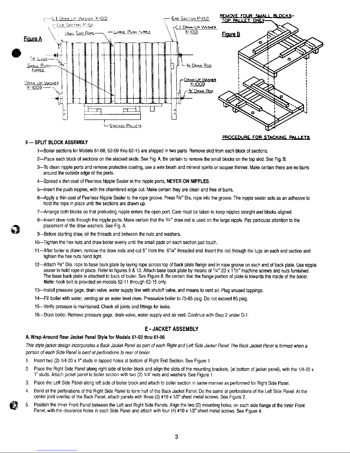
II-- SPLITBLOCKASSEMBLY
1--Boiler sectionsfor Models61-08,62-09thru 62-15are shippedintwo parts.Removeskidfromeach blockofsections.
2--Place each blockofsectionson the stackedskids.See Fig.A. Becertainto removethesmall blocksonthetop skid.See Fig.B,
3--To clean nippleportsand removeprotectivecoating,usea wire brushandmineralspiritsor lacquerthinner.Makecertainthereareno burrs
aroundthe outsideedgeof the ports.
4--Spread athincoatof PeerlessNippleSealerinthe nippleports,NEVERON NIPPLES.
5--Insert the push nipples,withthe chamferededgeout. Makecertaintheyare cleanand freeofburrs.
6--Apply a thin coatof PeerlessNippleSealerto the ropegroove.Press5/8"Dia.ropeintothegroove.Thenipplesealeractsasan adhesiveto
holdthe ropeinplaceuntilthesecgonsare drawnup.
7--Arrange bothblocksso that protrudingnippleentersthe openport.Caremustbetakento keepnipplesstraightand blocksaligned.
8--Insert drawrodsthroughthe nippleports.Makecertainthatthe3/4"drawrod is usedonthelargenipple.Payparticularattentiontothe
placementof the drawwashers.SeeFig.A.
9--Before startingdraw,oil thethreadsand betweenthe nutsandwashers.
10--Tightenthe hexnutsanddraw boilerevenlyuntilthe smallpadson each sectionjusttouch.
11--After boilerisdrawn,removethedraw rodsand cut 5" fromthe 6V4" threadedend.Inserttherodthroughthe lugsoneachendsectionand
tightenthehex nutshandtight.
12--Attach3/8"Dia.ropeto baseback platebylayingropeacrosstopofbackplateflangeandinropegrooveon eachendofbackplate.Usenipple
sealerto hold ropein place.Referto figures9 & 12.Attachbase backplate bymeansof V4"-20x lr/2" machinescrewsandnutsfurnished.
Thebase backplateisattachedtobackof boiler.SeeFigure8.Becertainthatthe flange portionofplateistowardstheinsideof the boiler.
Note: hook boltisprovidedon models62-11through62-15only.
13--Install pressuregage,drainvalve,watersupplylinewith shutoffvalve,and meansto ventair.Plugunusedtappings.
14--Fill boilerwith water,ventingair aswaterlevelrises.Pressurizeboilerto75-85psig.Do notexceed85 psig.
15--Verifypressureis maintained.Checkalljointsand fittingsfor leaks.
16--Drainboiler.Removepressuregage,drainvalve,watersupplyandairvent.ContinuewithStep2 underD-1.
E - JACKET ASSEMBLY
A.Wrap-AroundRearJacket PanelStylefor Models61-03thru 61-06
Thisstylejacket designincorporatesa BackJacketPanelaspart of eachRightand Left SideJacketPanel.TheBack JacketPanelis formedwhena
portionofeach SidePanelis bentatperforationsto rearof boile_:
I, Inserttwo (2) 1/4-20x 1"studs intappedholesat bottomof RightEndSection.SeeFiguret.
2. Placethe RightSide Panelalongright sideof boiler blockandalignthe slotsof the mountingbrackets,(atbottomofjacketpanel),withthe 1/4-20x
1"studs.Attachjacketpanel toboilersectionwithtwo (2)1/4" nutsandwashers.SeeFigureI.
3. Placethe Left SidePanelalongleftsideof boilerblockand attachto boilersectionin samemannerasperformedforRightSidePanel.
4. Bendat theperforationsofthe RightSidePaneltoform halfof the BackJacketPanel.Dothe sameat perforationsofthe LeftSidePanel.Atthe
centerjointoverlapof the Back Panel,attachpanelswiththree (3) #10x 1/2"sheetmetalscrews.See Figure2.
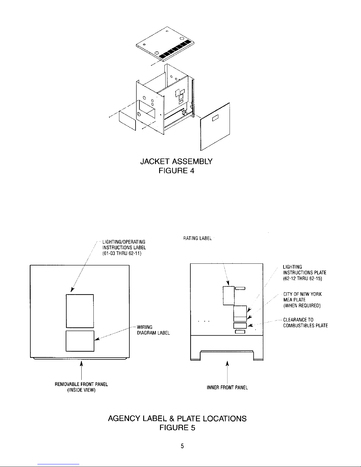
PositiontheInnerFrontPanelbetweenthe Leftand RightSide Panels.Alignthe two(2)mountingholes,on eachsideflangeofthe InnerFront
Panel,with the clearanceholesin eachSide Panelandattachwith four(4) #10x 1/2"sheetmetalscrews.See Figure4.
Page 12

6. PlacetheSecondaryAirCoverDooratbottomofInnerFrontPanel.ThetopbendoftheCoverDoorslipsoverthetopreversebendatcutout
openingoftheinnerFrontPanel.RefertoFigure11.
7. AtlachDraftHoodtoFlueCollectorwithtwo(2)#10x1/2"sheetmetalscrews.RefertoFigure10.
8. AttachtheLowerFrontPaneltothebottomtrontoftheLeftandRightSidePanelswithtwo(2)#10x1"sheetmeta_screws.SeeFigure4.
9. PositionTopJacketPanelsotheflangesoverlapSideJacketPanelsandairlouversareatthefrontoftheboiler.Securewithsix(6)#10x1/2"sheet
metalscrews.SeeFigure4.
10.AttachtheCleanOutCoverPlatePaneloveropemnginLeftSideJacketPanet,withfour(4)#10x1/2"jacketscrews.SeeFigure4
11.ThemanilaenvelopethatcontainstheInstallationManualalsocontainstheboilerratinglabel,clearancetocombustiblesplate,Lighting/Operating
instructionplateorlabelandwiringdiagramlabel.SeaFigure5forlocationofplatesandlabels.Attachplateswith#6x3/8"screwsprovided.
12.PositiontheRemovableFrontPanelinplacebyslidingthePanelunderthefrontflangeoftheTopPanelandthendownuntilitrestsonLowerFront
Panel.
B.IndividualBackJacket PanelStyle for Models61-07thru 62-t5
Thisjacketstyle hasaseparateBackJacketPanelthatis attachedtoindividualRightandLeftSidePanels.
1. AttachSide Panelsperinstructionsin #1thru3 above.SeeFigure1.
2. Positionthe BackJacketPanelonthe insideof theLeft and RightPanelflangesand attachwithsix(6) #10x !/2" sheetmetalscrews.SeeFigure3.
3. Followinstructionsaboveper #5thru 12for assemblyof remainingjacketpanels.
SIDE PANEL ATFACHMENT
FIGURE 1
-,_ RIGHT SIDE PANEL
ONEPIECERIGHT
SIDEANDREAR
PANEL
1/4" WASHER
1/4" NUT
J
J
ONEPIECE LEFT
SIDEAND REAR
PANEL
REAR VIEW WRAPPER
STYLE JACKET
(61-03THRU 61-06)
FIGURE 2
LEFTSIDEPANEL
RIGHT
SIDE
PANEL
REAR VIEW OF BACK PANEL
(61-07 THRU 62-15)
FIGURE 3
BACKPANEL
4
Page 13
JACKET ASSEMBLY
FIGURE 4
/
/
#,
, LIGHTING/OPERATING
, INSTRUCTIONSLABEL
(61-63 THRU 62-11)
" WIRING
_J
/jJ DIAGRAMLABEL
RATINGLABEL
LIGHTING
INSTRUCTIONSPLATE
(62-12 THRU 62-15)
CITYOFNEWYORK
• MEAPLATE
(WHENREQUIRED)
CLEARANCETO
COMBUSTIBLESPLATE
REMOVABLEFRONTPANEL
(INSIDEVIEW)
INNERFRONT PANEL
AGENCY LABEL & PLATE LOCATIONS
FIGURE 5
Page 14
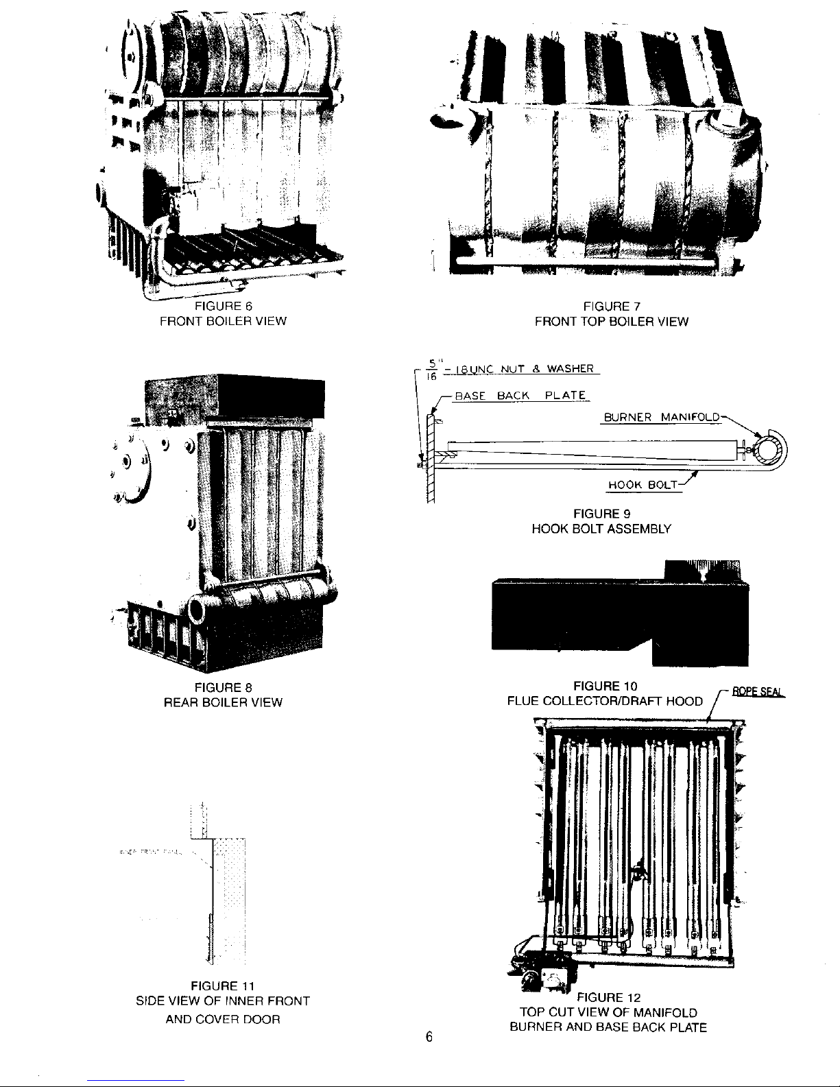
FIGURE 6
FRONT BOILER VIEW
FIGURE 7
FRONT TOP BOILER VIEW
T_6"- !_UNC NUT & WASHER
_BASE BACK_
-- PLATE
BURNER MANIFOLD-_
HOOK BOLT _'w
FIGURE 9
HOOK BOLT ASSEMBLY
FIGURE8
REAR BOILERVIEW
FIGURE 10
FLUE COLLECTOR/DRAFT HOOD
.f,
H
FIGURE 11
SIDE VIEW OF INNER FRONT
AND COVER DOOR
-"IGURE 12
TOP CUT VIEW OF MANIFOLD
BURNER AND BASE BACK PLATE
6
Page 15
F-VENTING
A.General
1--For connectionto gasventsor chimneys,ventinstallationshallbein accordancewith Part7,VentingofEquipment,ofthecurrenteditionof the
NationalFuelGas Code,ANSIZ223.1/NFPA54,orapplicableprovisionsofthe localbuildingcodes.
2--Draft: Sufficientdraftmustbeavailableforremovalof productsof combustion.If draftis notadequate,spillageofthe productsof combustion
will occuratthebottomoutletofthe drafthood.Ifsucha conditionshouldexistchecktheflueand chimneytodeterminecauseof insufficient
draft.It isalsoimportantthat ampleairis availablein theboiler roomtofacilitatedraft.
3--Vent connectorshouldslopeupwardat least1/4"per lineal footbetweenthe drafthood outletandthechimney.
4--Flue orvent connectormustbe insertedinto butnot beyondtheinsidewallofthechimneyflue.
5--Vent connectorsservingappliancesventedbynaturaldraftshallnot beconnectedintoany portionof mechanicaldraftsystemsoperating
underpositivepressure.
6--Horizontalportionsof theventingsystemsshall besupportedtopreventsaggingbyuseof metalstrappingor equivalentmeansandbe located
atno morethan 12ft. intervals.
7--When anexistingboilerisremovedfrom acommonventingsystem,thecommonventingsystemis likelytobetoo largeforproperventingof
theappliancesremainingconnectedto it.
Atthetime of removalof an existingboiler,thefollowingstepsshall befollowedwith eachapplianceremainingconnectedtothe common
ventingsystemplacedin operation,whilethe otherappliancesremainingconnectedtothecommonventingsystemarenot inoperation.
a.Sealany unusedopeninginthecommonventingsystem.
b.Visuallyinspecttheventingsystemforpropersizeandhorizontalpitchand determinethereisno blockageorrestriction,leakage,corrosion
andotherdeficiencieswhichcouldcausean unsafecondition.
c.Insofaras is practical,closeall buildingdoorsand windowsandalldoorsbetweenthespacein whichtheappliancesremainingconnected
to thecommonventingsystemarelocatedandotherspacesofthe building.Turnon any clothesdryersandanyappliancenotconnectedto
the commonventingsystem.Turnon anyexhaustfans,suchasrangehoodsand bathroomexhausts,so theywilloperateatmaximum
speed.Donot operateasummerexhaustfan.Close fireplacedampers.
d.Placein operationtheappliancebeing inspected.Followthe lightinginstructions.Adjustthermostatso appliancewill operatecontinuously.
e.Testfor spillageatthedrafthoodreliefopeningafter5 minutesof mainburneroperation.Usethe flameofamatchorcandle, orsmokefrom
a cigarette,cigar orpipe.
f. Afterit hasbeendeterminedthat eachapplianceremainingconnectedtothecommonventingsystemproperlyventswhentestedas
outlinedabove,returndoors,windows,exhaustfans,fireplacedampersandanyothergas-burningappliancetotheir previousconditionsof
use.
g.Anyimproperoperationofthecommonventingsystemshouldbe correctedsotheinstallationconformswiththecurrenteditionof the
NationalFuelGasCode,ANSIZ223.1/NFPA54.When resizinganyportionof the commonventingsystem,thecommonventingsystem
shouldberesizedto approachminimumsizeas determinedusingtheappropriatetableslocatedin the chapter"SizingofCategoryI Venting
Systems",inthe currenteditionof theNationalFuelGasCode,ANSIZ223.1/NFPA54.
8--Single WallTypeVentPipeshouldbefurnishedbetweenthedrafthoodandchimney.Iftheventconnectorshallbelocatedin orpass througha
coldarea,the ventconnectorshallbeoflisteddouble-wallTypeB or L material.
Page 16

B,VentDamperInstallation
1 Ventdampersare providedonmodels61-03through61-08as standardequipment.
2--Unpack theventdamperandfollowthese instructionsandthe installationinstructionsin theventdampercarton.Observethecautionsand
warmngthataccompanyallinstructions.Do notmodifyventdamperor boilerdrafthood
3--The ventdampercanbe mounteddirectlyontothe drafthoodoutletcollar,or in theventpipingclose tothe boiler.Seefigures14and 15,Be
suredirectionofflow arrowlocatedondampercollar,ispointingawayfromdraft hoodcollarand damperpositionindicatorisvisibleafter
installation,Forinstallationwithdampermountedin the horizontalposition,mountthedamperasshowninfigure15to avoidexcessiveheat
andpossiblecondensationdripsonthe damperoperatingcontrol.
4--Do not useoneventdamperto controltwo or moreheatingappliances.Seefigure 13.
5 Makecertainthatthe minimumclearancesprovidedinthe ventdampermanufacturersinstructionsaremaintainedandthatadequatespaceis
providedfor damperaccessand service.
6--A wiringharnessis packedwiththe ventdamperwith pluginconnectionsat eachendof theharness.Connectsmallerendinto dampermotor
receptacleand connectotherendto boileraquastatrelay_imit(on waterboilermodelsequippedan L8148Eor L8124Elimitcontrol),orboiler
junctionbox (onsteamboilermodels),
7--Damper mustbe in theopenpositionwhenappliancemainburnersare operating.
OTHERHEATING
APPLIANCE
I[_ OTHER
HEATING
APPLIANCE
INCORRECT CORRECT
Figure13:VentingMultipleAppliances
8
Page 17

SLOPE UP
A MINIMUM
OF 1/4"
PER FOOT -m
VENT
DAMPER
AS REQUIRED
DRAFT HOOD
OUTLET
Figure14:VentingwithVentDamperinVerticalPosition
/- VENT TO
SLOPE UP VENT /CHIMNEY
A MINIMUM DAMPER
oF1/4" "7F" 1
PER FOOT_ 11 O'CLOCK
r_
1 O'CLOCK
POSITION
OPERATOR
-CONDENSATION
ZONE
7 O'CLOCK 5 O'CLOCK
POSITION POSITION
DO NOT MOUNT DAMPER
OPERATOR IN SHADED REGION
SECTION A-A
Figure15:VentingwithVentDamperinHorizontalPosition
Page 18

G - PIPING
1--Hot Water:
a.The recommendedpipinghook-upis showninFigure17.Alsoreferto PeerlessWaterSurvey.
2--Steam:
a.Therecommendedpipinghook-upis shownin Figure16.Pleasenotethat a Hartfordreturnloopis recommendedtobe usedonall steam
boilers.Also referto PeerlessSteamSurvey.
3--The reliefvalveand popsafetyvalveshallbe installedbyusingthe3/4"x 3"nippleand 3/4"elbowsuppliedwith theboiler.Refertoillustrations
locatedinSectionR-"Ratings,Tappingsand DimensionalData".LargeNPTsizevalvesmaybe installedinsupplypiping.
NOTE:IFTHIS BOILERANDDISTRIBUTIONSYSTEMISUSEDINCONJUNCTIONWITHA REFRIGERATIONSYSTEM.THECHILLED
MEDIUMSHALLBEPIPEDIN PARALLELWITHTHEBOILERANDTHEPROPERVALVEAPPLIEDTOPREVENTTHECHILLED
MEDIUMFROMENTERINGTHE BOILER.A DRAWINGILLUSTRATINGTHIS HOOK-UPIS PROWDEDINFIGURE18.
WHENTHEBOILERIS CONNECTEDTOHEATINGCOILSLOCATEDINAIRHANDLINGUNITWHERETHEYMAYBE EXPOSED
TO REFRIGERATEDAIR CIRCULATION,THE BOILERPIPINGSYSTEMMUSTBE EQUIPPEDWITHFLOWCONTROLVALVESOR
OTHERAUTOMATICMEANSTO PREVENTGRAVITYCIRCULATIONOFTHEBOILERWATERDURINGTHECOOLINGCYCLE.
CAUTION:PIPETHEDISCHARGEOFRELIEFVALVETO PREVENTINJURYINTHE EVENTOFPRESSURERELIEE SUGGEST
DISCHARGETOBE PIPEDTODRAIN.PIPEFULLSIZEOFOUTLET.
H - GAS PIPING
1--Gas supplypipingistobe sizedand installedproperlyinorder toprovidesupplyof gassufficienttomeetthemaximumdemandwithoutundue
lossofpressurebetweenthemeterandthe boiler.
2_onsult the followingtablefor propersizingofgas piping for variouslengthsand diameters.
CAPACITYOF PIPEOF DIFFERENTDIAMETERSANDLENGTHSINCU. FT PERHOURWITHPRESSUREDROPOF 0.3 IN.AND
SPECIFICGRAVITYOF0.60. NOALLOWANCEFORAN ORDINARYNUMBEROFFITTINGSIS REQUIRED,
PipeLength 3/4" 1" 11h" 11/2"
Feet Pipe Pipe Pipe Pipe
10 278 520 1,050 1,600
20 190 350 730 1,100
30 152 285 590 890
40 130 245 500 760
50 115 215 440 670
60 105 195 400 610
MULTIPLIERSTO BEUSEDWITHABOVETABLE,WHENTHESPECIFICGRAVITYOFTHEGASISOTHERTHAN 0.60
SpecificGravity 0.5 0.55 0.60 0.65 0.70
Multiplier 1.10 1.04 1.00 0.962 0.926
3.-Locate the droppipe adjacentto,butnotinfrontof theboiler.
4--Locate a tee in thedroppipeat sameelevationasthegasinletconnectiontothe boiler.Extendthedroppipetoa pipecapasshownin Figure
19to formasedimenttrap.
5--Install a groundjointunionaheadofthe gascontrolassemblyto permitservicingoftheequipment.See Figure19.Somelocalcodesrequirean
additionalshut-offvalve.Ifyourcoderequiressucha valve,a suggestedlocationis shownin Figure19.
6_OTE: Wheninstallingboilerbesureapipecompoundresistanttotheactionof liquefiedpetroleumis used.
7--Check pipingforleaks.Alwayscheckleakswitha waterandsoapsolutionor equal.DONOTUSE A FLAMEFORCHECKINGGASLEAKS,
8--The boilerandits individualshut-offvalvemustbedisconnectedfromthegassupplypipingsystemduringanypressuretestingofthatsystem
attest pressuresin excessof r/2psig (3.5kPa),
Theboiler mustbeisolatedfromthegassupplypipingsystembyclosingits individualmanualshut-offvalveduringany pressuretestingof the
gassupplypipingsystemat testpressureequalto or lessthanV2psig(3.5kPa).
10
Page 19

Table1:SteamHeader,Risersand EqualizerSizing
L---RETURN
SUGGESTEDPIPING
t t
ETURN
NOTE:Thereturnfrom systemshouldalwaysenterequalizer
throughHartfordLoop,approximately2"- 4" below
normalwaterline.
Steamheadershouldbe24" rain.aboveboilernormal
waterline.
Figure16:SteamSupplyand ReturnPiping
Model No.Supply Size of Header Equalizer
No. Outlets Outlets Supply Size
6t-03 1 2" -- 1114"
61-04 1 2" -- 11/4"
61-05 1 2" -- lr_"
61-06 2 2" 21_" 11_"
61-07 2 2" 2+/2" 11_"
61-08 2 2" 3" 11_"
62-09 2 2" 3" 11_"
62-10 2 2" 3" 1!_"
62-11 2 2" 3" 1_"
62-12 3 2" 31_" 11_"
62-13 3 2" 31_" 11_"
62-14 3 2" 31_" tl_"
62-15 3 2" 31_" 11_"
STEAM BOILER
SUGGESTEDPIPING
HOT WATERBOILER
_TOP • w_STt ¥_LV[ (Nomwl_eJrY O_J_W_
Cu_{D _to _ [xF_l_,_ TANK
_ S_T_II_ESS v,_Tl_ ;_'_1_ is _ _Fw°_ ;4(ATW4G<
Figure 17: Hot Water Supply and Return Piping
11
Page 20

Figure18:ParallelHook-UpwithWaterChiller
J
SERVICE
_JACKET
G.J. UNION
SEDIMENT TRAP
_./FLOOR LINE
Figure19:GasConnectiontoBoiler
Figure20:GravityHotWater
Figure22:SteamW/FloatLWCO
Figure21:ForcedHotWater
.HIGH TEMPERATURE
HOT WATER _.
MIXEO
WATER
MIXER
HEATER
"rAPPING
12 Figure23:SuggestedPipingForTanklessHeater
Page 21

A
c
©
o ©
F_
1/2 TAPPINGS
TO MOUNT
9 1/4 LONG
GAUGE GLASS
FROM PROBE
L.WC.O. CARTON
L_ I_
RIGHT SIDE PANEL
Figure24:Steam:PrimaryProbeLWCO,HydrolevelCG400P
THRU
i1_11 _.
I
I
Figure21A
IMPORTANT
1. InspectProbeElectrodeannuallyfor scaleandbuild-upand cleanif necessary.
2. Forpropermaintenance,recommendedwaterfeederapplicationsandoperation,refertotheHydrolevelProbeLWCOInstallationInstructions.
• °
LEFT I';AhlD OPPOSITE
F3 TI
Figure 25: Steam: Gauge/Pressuretrols Piping Arrangement
t[[
Figure26:Steam:Gauge/PressuretrolsAlternatePipingArrangement
13
Page 22

Figure27:ProbeLWCOLocationfor HotWaterBoiler
I - CONTROLS
l--Steam:
a.Forproper}ocationofcontrolsandaccessoriesreferto SectionR"Ratings,TappingLocationsandDimensionalData".
b.TheMcDonnell& Miller#67PE-2LWCOisfurnishedasa standardwith all steamboilers.TheHydrolevelCG400-PPrimaryProbeLWCOis
optional.This controlprovidesa lg minuteon cyciefollowedby a 90secondoffcycle.Thisfeatureallowsthe waterlevelinboilerto settleso
thattheprobe cansensea true waterlevel.
c.TheHydrolevelCG550-P ProbeLWCOmaybeusedin combinationwitha PrimaryFloatLWCOandisto bemountedinthe secondary
probelocation.
1.TheCG550PLWCOincorporatesa 10minuteon cyclefollowedbya 90secondoff cycle.
d.Whena 67PE-2FloatLWCOissupplied,thepressuretroland brasssiphonare mountedontop ofthe 67PE-2.Thisisstandardformodels
61-03thru 62-1t. Refertofigure22.The67PE-2is providedwithfittingsto attachdirectlyto tappingsA and B,asshowninfigure24.The
20q05-10gaugeglassset isinstalledas partof the67PE-2quickhook upfittings.
e.WhenaHydrolevelCG400-PPrimaryProbeLWCOis supplied,the pressuretrol,brasssiphonand gaugearemountedasshowninfigure
24.Thefittingsrequiredformountingthesethreecomponentsarefoundinthe ProbeLWCOCartonand theSteamTrimCarton.
A longergaugeglassw/rods, (22-162-10carton),arerequiredforusewith the HydrolevelCG-400-Pprobe.Two1/2"x 3" nipples,two1/2"
couplers,longergaugeglassw/rodsand gaugevalvesare mountedintoTappingsA andC asshowninfigure24.ForPackagedBoilers,
theseparts are suppliesinthe Misc.PartsCarton,locatedin boilercrate.ForKnockdownBoilers,usethegaugevalvesfoundin20-105-10
WaterGaugeCarton,whichis packedinthe SteamTrimCarton.Thelongergaugeglassw/rodsandfittingsare in PrimaryProbeLWCO
Carton.
NOTE:REFERTO FIGURE25 AND26 FORMOUNTINGOFDUALPRESSURETROLS,FORMODELS62-12THRU62-15
CAUTION:Ifusingchemicaladditivesto preventfoamingandsurging,suchas "Squick",watchthegaugeglassandshutdownboilerif water
disappearsfrom glass.Thencyclethe boilera fewtimesuntil the waterstabilizes.
2--Hot Water:
a.Forproperlocationofcontrolsandaccessoriesreferto SectionR "Ratings,TappingLocationsandDimensionalData".
NOTE:A HOTWATERBOILERINSTALLEDABOVERADIATIONLEVELMUSTBE PROVIDEDWITHA LOWWATERCUTOFFDEVICE
EITHERAS A PARTOF THEBOILERORATTHETIMEOFBOILERINSTALLATION.
b.WhenaprobeLWCOis provided,installprobeLWCOin supplypiping.
Supply Piping (left or right).
Note:This mountingmethoddoesnot requirea probewitha timed on/offfeature.
1. Instal_a2" x 10" inch or longer nipple in the boiler supply tapping. Install a 2" x 2" x 3/4"
tee on the nipple. See figure 27.
TO SYSTEM
__ 2,,x
2 X 10 ] I,P" TEE
NIPPLE _
RO Eo'
2. Install theremainderof the boilersupplypiping.Pipesizemaybe reducedasrequired.Referto low
watercut off manufacturer'sinstructionsfor installationandmaintenanceprocedures.
Do not install a probe low water cut off in the boiler primary or secondary probe tapping unless the
low water cut off is equipped with a timed on and off feature. The cycled off time will allow the probe
low water cut off to sense the true water level in the boiler and eliminate a false reading caused from
sensing a foaming or surging water condition. Failure to use a timed low water cut off could result in
a failed heat exchanger.
14
Page 23

3--Specificdetailsregardingthe installationofthe variouscontrolsaregiveninthe controlsheetsattached.
4--In theeventofa controlfailurethe replacementshallbe identicalwiththeoriginalequipment.
5_n certainmodelsa separatepilot switchmustbe used.Theswitchshallbe mountedonthe leftsideoftheinnerfrontjacketpanel.Usethe
twoYs"holesprovided,if holesare not provided,drillaccordinglyasshowninFigure45.
6--For Models61-08,62-09thru62-16the sparkignitioncontrolboxwhensupplied,mustbe mountedon theouterleftsidejacketpanelasshown
in Figure43. Ifadditionalspark ignitioncontrolboxis supplied,this mustbemountedto the outerrightsidejacketpanel.
7--For Models61-03thru61-07thesparkignitioncontroland mountingbracket,whensupplied,canbe mountedto the rightor left outerjacket
panelas requiredfor easeof wiring.
8--This boilermaybesuppliedwithsafetylimitsinadditiontothe highlimitaquastatandpressuretrol.Thefollowingisa descriptionoftheselimits
andhowtheyworkin conjunctionwith thesafe operationof theboiler.
a.FLAMEROLL-OUTSAFETYSHUTOFFSWITCH--ForModels61-03thru61-08ONLY,this is athermallyactivatedswitchthat is located
onthe burneraccesscoverplate.The flameroll-outsafetyshutoft switchwill senseexcessivetemperaturecausedbycontinuedflameroll-
outand shutdownmainburnergas.This is a non-recyclingswitchthat mustbereplacedonceit hasbeenactivatedandthe causeof the
roll-outeliminated.
b.VENTSAFETYSHUTOFFSWITCH--ForModels61-03thru 61-08ONLY,this is a thermallyactivated,manuallyresetableswitch,located
inthe drafthoodreliefopening.Ifventingsystembecomespartiallyortotallyblocked,thevent safetyshutoff switchwill senseexcessive
temperaturecaused byflueproductsexitingthe drafthoodreliefopeningandshut downmainburnergas.
NOTE:REFERTOSECTIONQ FORINSTRUCTIONSWHENBOILERISSHUTDOWNBYTHEACTIVATIONOFEITHEROFTHEABOVE
SWITCHES.
9--Water & SteamModels62-12lhru 62-15are suppliedwith2 limitcontrols.Themanualresetlimitmustbe setfor a highercut out pointthanthe
operatinglimitcontrol.If aThermostatis usedas an operatingcontrol,itshouldbeusedin additiontoand not in lieuofthe operatinglimit
control.
NOTE:THISBOILERSHALLBEINSTALLEDSOTHATTHEGASIGNITIONSYSTEMCOMPONENTSAREPROTECTEDFROMWATER
(DRIPPING,SPRAYING,ETC.)DURINGAPPLIANCEOPERATIONANDSERVICE(CIRCULATORREPLACEMENT,CONDENSATE
TRAP,CONTROLREPLACEMENTS,ETC.).
J - WIRING
NOTE:]HISUNITWHENINSTALLEDMUSTBEELEC'rI_AU.YGROUNDEDINACCORDANCEWI]HTHEREQUIREMENTSOF]HEAU_ HAVING
JURISDIC'I]ONOR,INTHEABSENCEOFSUCHREQUIREMENTS,wm.ITHECURRENTEDmONOF]HENATIONALELECTRICALCODE,ANS_FPANO.70,
IFANEXTERNALELECTRICALSOURCEISUI1L_D.
1--All electricalwiringshallbe donein accordancewithTheNationalElectricCodeANSI/NFPA70andlocalrequirements.
2--For recommendedwiringof controls,referto Figures28 thru42.SeeFigures20,21,22 and 24forlocationof wiringand controls.
3--A lengthof 150° C lowvoltagewireis provided.
4--The boilershouldbeconnectedbya separate,permanentlyliveelectricalsupplylinewithafusedswitch.
5--ThermostatAnticipatorSettings:(note:settingsmayneedtobe adjustedupor downfromset pointsnotedbelow)
a.Setto .4ampwhena 8222A-1002IsolationRelayisapplied.
b.NI othersystems,matchanticipatorsettingtoamploadof24 voltcontrolcircuit.
NOTE:Singlepole switchesincludingthoseof safetycontrolsor protectivedevicesshall notbe wired ina groundedline.
CAUTION:LABELALLWIRESPRIORTO DISCONNECTIONWHENSERVICINGCONTROLS.WIRINGERRORSCANCAUSEIMPROPERAND
DANGEROUSOPERATION.VERIFYPROPEROPERATIONAFTERSERVICING.
K - STARTING BOILER
1--Referto INSTRUCTIONSFOROPERATIONandthe lighting/aperatinglabelwhichis mountedtojacketpanel.
2--The boilerand itsgas connectionmustbe leaktestedbeforeplacingtheboilerin operation.Checkgasconnectionswithsoap solution.
15
Page 24

L1 - ADJUSTMENT TO GAS PRESSURE REGULATOR
1--Set manifoldpressureasfo_lowsforvariousgases.
a.NaturalGas................ 31/2"WaterColumn b,LiquefiedPetroleumGas ................ 10"WaterColumn
2--To adjustgaspressure,turnadjustingscrewof gaspressureregulator,outto decreasepressure,turnintoincreasepressure,Refertocontrol
sheetssuppliedwith boilerfor locationofgas pressureregulator•
3--In no caseshouldthe finalmanifoldpressurevarymorethanplusor minus03 incheswatercolumnfromtheabovespecifiedpressures•Any
necessarymajorchangesintheflowshouldbemadeby changingthe sizeofthe burnerorifice.
MinimumPermissibleSupplyPressurefor Purposeof InputAdjustment.... 5.0" W.C.NaturalGas 11.0" W.CLiquefiedPetroleumGas
MaximumPermissibleSupplyPressuretothe Boiler .................. 13.5" W.C.NaturalGas 13.5" W.CLiquefiedPetroleumGas
NOTE:MINIMUMRATEAS SHOWNONTHE RATINGPLATE!S OBTAINEDBYA FIXEDORIFICELOCATEDINTHEGASTRAINANDISNOT
ADJUSTABLE•
L2-ADJUSTMENTOF PILOTGASFLOWWITHMR8200ANDMR8300COMBINATIONGASVALVES
Tomaximizethermocouplelife,particularlyonnaturalgasinstallationswithgassupplypressuresabove9" W,C.,reducethepilotgasflow.
WARNING:TURNOFFALL ELECTRICPOWERTOTHEAPPLIANCE.TURNGASCONTROLKNOBTO "PILOT'POSITION•
1--Locate and removethe pilotadjustmentcapscrew,whichisadjacenttothepilottubeconnectionontopof gasvalve.
2--Removepilotobservationcoverdoor.SeeFigure11.
3--Turn the pilot adjustmentscrewclockwiseuntilthe pilotflameextinguishes•Then increasethe pilotflow justtothepointthatthegasvalveholds
in whenrelightingthe pilotpersteps9 and 10of LightingInstructionsonpage25 (turnscrewno morethana 1/8turn).
NOTICE:THEFIRSTFEWTURNSOFTHEADJUSTMENTSCREWMAYNOTCAUSEANYCHANGEINTHEPILOTFLOW.SUBSEQUENT
PARTIALTURNSOFTHE ADJUSTMENTSCREWMAYHAVEA GREATIMPACTON PILOTFLOW.
4--Turn on electricpowertothe appliance.
5--Turn GasControlKnobto"On"positionperthe LightingInstructionsonpage25.
6--Verify pilotremainslitaftershutdownfroma boiler"ON"cycleof at leasttenminutes,If pilotextinguishes,followLightingInstructionsonpage25
andagainslightlyincreasepilotflow.
7--Make a fina_slightincreaseinthe sizeofthe pilottoensuresufficientpilotsignal underalloperatingconditions,justtothepointthat youobserve
a slightincreaseinthesizeof theflame (nomore thanan 1/8turn).
8--Replace adjustmentcapscrew andobservationcoverdoor•
M-BURNERINPUT
1--Referto ratinglabelmountedon thejacketinner-frontpanelto obtainthe requiredBTUper hourinput•Innocaseshallthe inputtotheboiler
exceedthat shownonthe ratinglabel.
2--Checkinputbyuseofthefollowingformula:Suggestreadingmeterfor2 Cu.Ft.
_Q0 x Fx H_ BTU/Hr.Input
T
3600 -- Secondsperhour
F -- Cu.Ft.GasRegisteredonMeter
H -- HeatValueofGas inBTU/Cu.Fb
T -- TimeinSecondsofMeterisRead
NUMBER OF ORIFICE SPUDS REQUIRED
MODELNUMBER-- 61-03 61-04 61-05 61-06 61-07 61-08 62-09 62-10 62-11 62-12 62-13 62-14 62-15
ORIFICESPUDS-- 4 6 8 10 12 14 16 18 20 22 24 26 28
• k
16
Page 25

HONEYWELL 24V STANDING PILOT - STEAM w/DAMPER, FLOAT LWCO AND ISOLATION RELAY
Models61-03thru61-08
2_v 7
I
TST_ _LA¥ COIL
I F
_ ml I
R _ RELAY II I
_ADC,CR LEr_ND
LINE VOLTAGE
LO_ VOLTAGE
_TUB _AP,NES$
X_ _X
H V88_
Figure28
HONEYWELL 24V STANDING PILOT- STEAM OR GRAVITY HOTWATER
Models62-09thru62-11
/ r_'f_
Figure29
17
Page 26

HONEYWELL SPARK IGNITION (HSP) - GRAVITY OR STEAM w/DAMPER, FLOATLWCO AND ISOLATION RELAY
Models61-03thru61-07
-- ?
TRANSFORME_
120V
_J_J_J
I
TSTAI F_ELA_"COIL
_R L I I SpARK
IAODER tECENO
:IN_ VOLTAGE
_OW VOL_SE
ilrl
Figure30
HONEYWELL SPARK IGNITION (HSP) - FORCED HOTWATER w/DAMPER
Models61-03thru61-07
4_OJTJL_
Z4_
' / ?v"
......... _ : _ -4,
_)_ ..........................._t _. _ ,, _l_._ _L,._J _...........
, i i i
_ _ ,
_ /_ , ,
• w
i i ii i 1_ !
Figure31
18
Page 27

HONEYWELL SPARK IGNITION (HSP) - FORCED HOTWATER w/COIL AND DAMPER
Models61-03thru61-07
_--_ ..... _-rr'ccc_..... _'-.... -
I
i....
L............ _w...... L I i _ I
....
_---= __=__-_2
-- L_IN__,rAG_ _tt 14 _ rY_ TW
........ IC_ _ SiZE 16 _ BO'C STA,*I,_O W,RI_
I@_ -* ..... , ............
* 1
@
L...... __'..iJ__J z-__.,qt_ •
, i
• _ x- __+J
Figure32
HONEYWELL SPARK IGNITION (HSP-2) - GRAVITY OR STEAM w/DAMPER, FLOATLWCO AND ISOLATIONRELAY
Model61-08only
OPERAnNGCO_IFtOL O_
120V_60HZ r_ERUOS_I ISOLAtiON_[tAY H-RB222A IC,0_
TRANSFORMER
.... <.o.<t!, ; • ....
I LOW WAEP,Cu_-Orr
_ L ME _3LtC_JT
I I I COt_TFIO_S
_'_ _ _ _lii ' 1
SmEi HARNESS_ Il I Z: i %\ flING HIN SS u i FILO:_RNER _, I C_BL_ _ I , , _BL_ A
_RC_ D roif i_ x 7039 _ i _ I I PILOT BURN[R
--.......... _ppkor GAS._ L _LO_ iigAIN LOW VI_IA_ "Z[ 15 A" " C 51R_D£D "R<.............. L_.,_,, R _-- _--1-- -- --J_'
-- LINE VOtTACE VAL',_
VAL , ,_,_5 V;*L_ H VRll_<14
¢OL .... LOW VOLT,_Gt"SIZE 16/'2 A_ POll UkilErl FIRE
pROIE_TI_ _I_JNALqN__II!_ULT¢_E IflS'C
_ROUND LEAEitI4N_IZ_ If Al_f__<1" C SIRAN_I] II_ll[
MORES ALL _4111N8HUST CC_4mty141H I_PLIOABLE _(:(YES 0RDINAN_[_ #*bid RECNLAllI:_t5
In ANY I Ill( ilCINAL _I4N[AS _PPU[I_ li4]H [HE _P_IANg[ MU_T
BE FIEPL#*CE_IT IdUSTI_ REPLACED1,41H11411[A_ _H_)l_ldt ITS EQUIVALENI
Figure33
19
Page 28

HONEYWELL SPARK IGNITION (HSP-1) - w/DUAL 24V MAIN GASVALVES
Models62-09thru62-15
_j m
1 [ ................
i i ;
i i
_,L W_ _ _,V___ _T_ _ICA_[ COOlS. C,_O_',_ES. A_ _1'_ A_IC,_S,
Figure34
HONEYWELL SPARKIGNITION (HSP-1) - w/DUAL 120V MAIN GAS VALVES
Models62-09Thru62-15
........"F
............ [ ' ! ....... "
_ _, _D ,_ ,¢_,_ ._=_.p_,x _L_._. *,.,_ _0_ T_pL_;T _
NOTES=
=
Figure35
2O
Page 29

WIRING APPLICATION OF HYDROLEVEL PROBE LOW WATERCUTOFFS
Models550P,650PandCG550P
RefertoSectionI - Controlsofthis manualformountinglocationandinstructions.
115V-60HZ
L2 L1 (HOT)
£
L
TO L2 ON
WIRING DIAGRAM _,
--I1_- 115V-60HZ
ALARM CIRCUIT
(WHEN REQ'D)
sTO L1 ON WIRING DIAGRAM
NOTES:
ALL WIRING MUST COMPLY W!TH APPLIANCE CCDE3,
ORDINANCES, AND REGULATIONS
(_) PLACE JUMPER
Figure36:WiringofProbeLWCO
21
Page 30
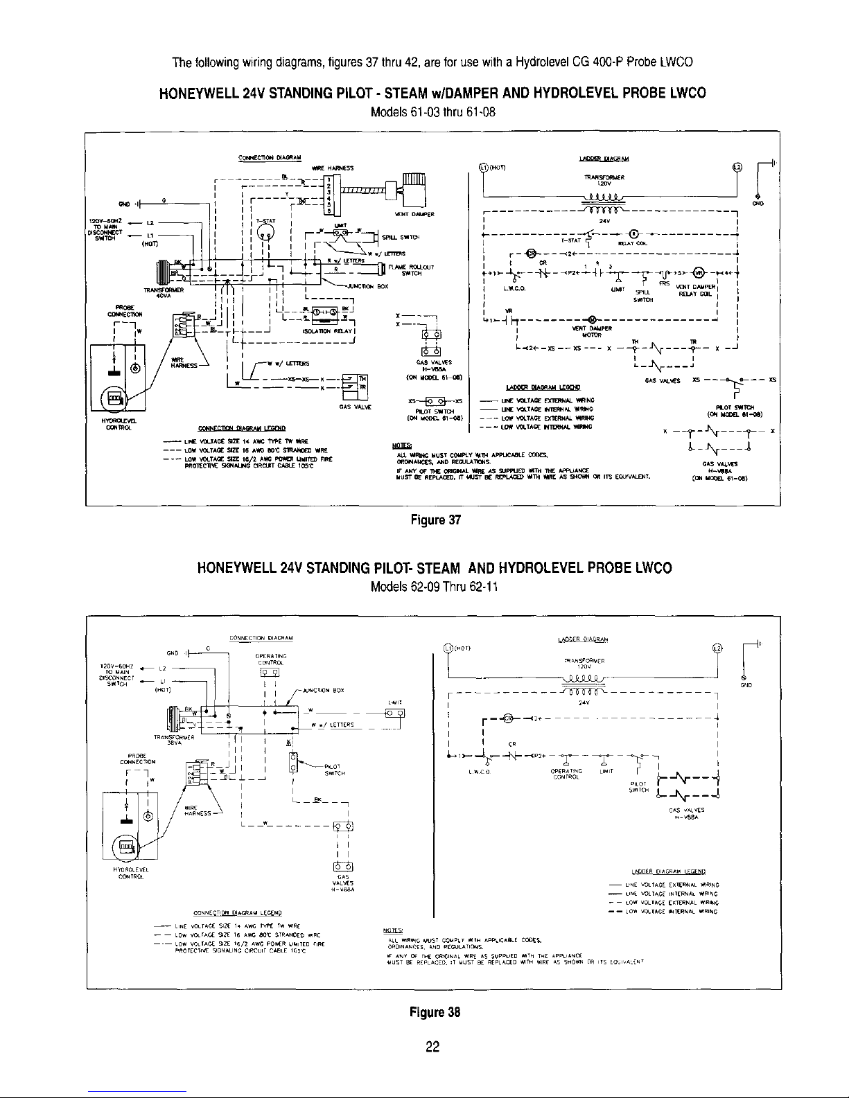
Thefollowingwiringdiagrams,figures37thru42,areforusewitha HydrolevelCG400-PProbeLWCO
HONEYWELL 24V STANDING PILOT - STEAM w/DAMPER AND HYDROLEVEL PROBE LWCO
Models61-03thru61-08
_SCON_J_T
S_TC _ -- L1
(HO
mANSF_
4OVA
PROBE
_E C_I_t -- -
r],
-- UN£ ",_.TA_ Sa21E14 AW_ _ TW tF, E
-- __ LOw t@-T_ NIl 1_/2 A_4_ _ UMI11_ RF_
C_,INEC_ _A_AU
_ H_ESS
r F
R
I : F _¢ _ _kL S_
I
I I I I r--
I x---_
I
L / _, ,
i___w w/ _ _ vat.s
- ---,=-_-- _<Zz_r_ 1 ion._o___ =1
CAS VAL_ _S---_-_XS
(ol+ii_ 61-0_)
ALL I_IRING MUST COMPly _n_ APP',JOm_
IF" ANy OF _ O_dG_NALI_R_ AS _JPPU_ _ _ P4_PI_AN_E
MUST _ REPtJ_C_O, IT 141JST BE R_PLl_ll_ _l113t llIRE AS SitO_I_4OR I/'3 _CAJIVALD_T.
/
RLOT metC_
-_---%---_- x
_-_N____
Figure37
HONEYWELL 24V STANDING PILOT-STEAM AND HYDROLEVEL PROBE LWCO
Models62-09Thru62-11
HYO_OLEV_L
CO_TRC_
CONNECTION DIAGRAU LEC,_NO
-- UN£ vo_r,_c_ _Z_ i,, _,wc WP[ _w ,_
LOW VO_IAC_ _zt _/2 ,_w_; pO_R UMIT[D rIFle
_OTE¢_V_ _ON_.LING ¢l_tCulr CABLE IO_:
I I
I I
V88_
I I
I I cR
L_co OP_R,_T_G LIMIT
CONTROL
L
F ....... J_ ]
I r--'@-_+ ....
I
I
.....
..... __N___ 4
G_S VALES
V88A
LADDEROAGIIAW G NB
U_E V0LrAG£ EXI[R_AL '_I_ING
GND
Figure38
22
Page 31

HONEYWELL SPARK IGNITION (HSP) - STEAM w/DAMPER AND HYDROLEVEL PROBELWCO
Models61-03thru61-07
CO_EClrO_ I_AGRAM
MRE HARNESS
! i i]ilZSS]
............ _1 . T,E,.O_,,T L....... I_,%
TRAN_C_M( R "l _
*,OVA
HY'OROLEVEL
CONNECTION =ACRa_ LEGE_ ! )WBK _ P_LOT BURN[r
m I¢_IIlON k _,_N_NG CABLE
LOWVOLI'_CE _ZE _6 _,WG aO_ STRa_C_D V4RE
---- LOW VOLIACE _ZE 16/2 AWG pO_'_ERLIM_TEOnRE G*_S vaU_
PROECnVE SIgnALING CIK'CUIt CABLE 105_3
O I_1_O N COnTr.. lgR_IN;*L
_) CROdND LE^0_E SIZE t6 AWC _00',3 _TRAND_D 'MI_E
T_N_FORME _
24V
/
•_,,---,_---.1_........ ;g Fo _ ,_ "p....... @.......
<_ _ rRS
LW¢O u_m_ _LL
,m
......_F: ......... ® ....................................
: VEN] _AMpE_? IGNIIE R
-- UN_ VOL;ACE INERNAL _IRING
UV
..... LOW _IDL_CE INT_RNA L _4RING : O=..=J_t _ .V/F=V
ALL _NG MUST COMPLY _ APPUCA_E CODEg G_ V_LVE
ORDNANCES AND _[_UL_T_OnS
rr AN_ OF THE oN6mNAL _E AS _PPLIED _'_TH THE A_IANCE
_USJ 8( r_EpLA¢£D tT _lUgT _ RfPL_Cf_ _TH WIRE AS SHO_IN OR FTS [oUWAI_NT
Figure39
HONEYWELL SPARK IGNITION (HSP-2) - STEAM w/DAMPER AND HYDROLEVEL PROBE LWCO
Model61-08only
PROT_CTNES_ O_O_t C_t£ I_
-fir
,,
I i*-nm"_ m_ __
I[' "%
e_s v,_u_
r..--- ¢[
i
v_v_
_o_
Figure40
23
Page 32

HONEYWELL SPARK IGNITION (HSP-1) - w/DUAL 24V MAIN GAS VALVESAND HYDROLEVEL PROBE LWCO
Models62-09thru62-15
............Ti(HOt)
IRANsrO_E_
_OV
_J3LLLt_
o,o
_'Iv i
I I
....
VAL_
-- LING VOtT;_C[EXT_F_N_L _e,NG
Figure41
HONEYWELL SPARK IGNITION (HSP-1) - w/DUAL 120V MAIN GASVALVES AND HYDROLEVEL PROBE LWCO
Models62-09thru62-15
CONNCC_ON DIACP,_U
rIIIC0_NECT _ i I I I
v • _ f I
.+,1 /_ \\ m ; j
- ' _ iiP _ -- G_S VALVES
HYr)NOLfV[L I t _
,,,..<,.,°%,,.,,y,,,,_,:,.,?,,,o,< ,..... W _-_ ]
ION'T'ON CONISOL I_P,'_INAL
_) GRoUNO LEAOIRE _ll{ 16 J_ 200C STRANDED IRE
(H°T) IRI 2RI 2_
T_AN_'0l_ ER
_V I
r_ ___.,._ .......
i IC'WITER I
; t :.- _ --_ - .<p2e
-- pr_A _ '_T _V _V/PV PV icN_o_
_wco OG _G LMIT _C (
I I I
,,
| |
-- LINGVOLTAGE E_IERNAL ,_RINe _I-- _
_C2_5
Figure42
24
Page 33
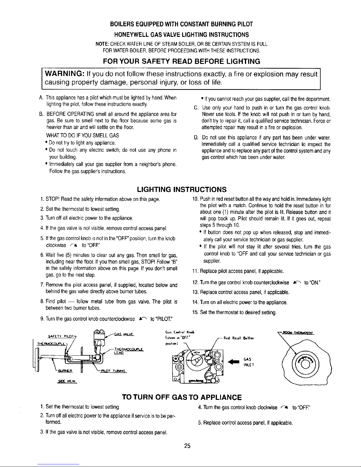
BOILERSEQUIPPEDWITHCONSTANTBURNINGPILOT
HONEYWELL GAS VALVELIGHTINGINSTRUCTIONS
NOTE:CHECKWATERLINEOFSTEAMBOILER,ORBECERTAINSYSTEMISFULL
FORWATERBOILER,BEFOREPROCEEDINGWITHTHESEINSTRUCTIONS.
FOR YOUR SAFETY READ BEFORE LIGHTING
WARNING: If you do not follow these instructions exactly, a fire or explosion may result
causing property damage, personal injury, or loss of life.
A, This appliance has a pilotwhichmust be lightedby hand.When
lightingthepilot, follow theseinstructionsexactly.
B. BEFORE OPERATINGsmell all around theappliance area for
gas. Be sure to smell next to the floor because some gas is
heavier thanair and will settleon the floor.
WHATTO DO IFYOUSMELL GAS
• Do not try to light any appliance.
e Do not touch any electric switch; do not use any phone in
your building.
• Immediately call your gas supplier from a neighbor'sphone.
Followthe gas supplier's instructions.
C,
D,
• Ifyou cannot reachyourgas supplier,callthe fire department.
Use only your hand to push in or turn the gas control knob.
Neveruse tools. If the knob will not push in or turn by hand,
don't try to repair it, call a qualifiedservicetechnician.Forceor
attemptedrepair mayresult in a fireor explosion,
Donot usethis applianceif anyparthasbeenunderwater.
Immediatelycall a qualifiedservicetechnicianto inspectthe
applianceandtoreplaceanypartofthecontrolsystemandany
gascontrolwhichhasbeenunderwater.
LIGHTING INSTRUCTIONS
1.STOP!Read the safety information aboveon this page.
2. Set the thermostatto lowest setting.
3. Turnoff all electric powerto the appliance.
4. If the gas valve is not visible, removecontrol access panel.
5. If the gascontrol knobis not inthe "OFF"position,turnthe knob
clockwise _ to"OFF."
6. Wait five (5) minutesto clear out any gas. Then smell for gas,
includingnear the floor.Ifyou then smell gas, STOP! Follow"B*
in the safety informationabove on this page. If you don't smell
gas, go to the nextstep.
7. Removethe pilotaccess panel, if supplied, located below and
behind the gas valve directly above burner tubes.
10.Pushinredresetbuttonallthewayandholdin.Immediatelylight
thepilotwitha match.Continueto holdthe resetbuttoninfor
aboutone(1) minuteafterthepilotis lit.Releasebuttonandit
will popbackup,Pilotshouldremainlit. If it goesout,repeat
steps5through10.
• If buttondoesnotpop upwhenreleased,stopand immedi-
atelycallyourservicetechnicianorgassupplier.
• If the pilotwill notstay lit after severaltries,turn the gas
controlknobto "OFFandcallyourservicetechnicianor gas
supplier.
11.Replacepilotaccesspanel,ifapplicable.
12.Turnthegascontrolknobcounterclockwise_ to=ON."
13.Replacecontrolaccesspanel,ifapplicable.
8. Findpilot followmetaltube from gas valve.The pilot is
betweentwoburnertubes.
9.Turnthegascontrolknobcounterclockwise_ to"PILOT"
14.Turnonallelectricpowertotheappliance.
15.Setthethermostattodesiredsetting.
S_E _Ew
Ga* Cont,_l Knob
(-_n ,,_"OFF" Rtd Reset 8ulto*
P°""') _ S
tNL[T
TO TURN OFF GAS TO APPLIANCE
1.Setthe thermostat to lowestsetting. 4. Turnthe gas control knob clockwise _ to "OFE"
2. Turnoff all electric powerto the applianceif service istobe per-
formed. 5. Replacecontrol access panel,if applicable.
3. If the gas valve isnot visible, removecontrol access panel.
25
Page 34

BOILERS EQUIPPEDWITH ELECTRIC IGNITION AND A COMBINATIONGAS VALVE
OPERATING INSTRUCTIONS
NOTE:CHECKWATERLINEOFSTEAMBOILER,OR BE CERTAINSYSTEMISFULL
FORWATERBOILER,BEFOREPROCEEDINGWITHTHESEINSTRUCTIONS.
FOR YOUR SAFETY READ BEFORE OPERATING
WARNING: If you do not follow these instructions exactly, a fire or explosion may result
causing property damage, personal injury, or loss of life.
A. This appliance isequipped with an ignitiondevice which auto-
matically lightsthe pilot.Do not try to lightthe pilot by hand.
B. BEFORE OPERATINGsmell all around the appliance area for
gas. Be sure to smell next to the floor because some gas is
heavier thanair and will settle on the floor.
WHATTO DO IFYOU SMELL GAS
• Do not try to light anyappliance.
• Do not touchany electric switch; do not use any phone in
yourbuilding.
• Immediately call your gas supplier from a neighbor's phone.
Followthe gas supplier's instructions.
C.
D,
• If youcannotreachyour gassupplier,call thefire department.
Useonlyyourhandto pushin or turn thegascontrolknob.
Neverusetools.Ifthe knobwillnotpushin orturn by hand,
don'ttryto repairit,callaqualifiedservicetechnician.Forceor
attemptedrepairmayresultinafireor explosion.
Donotusethis applianceif anypart hasbeenunderwater.
Immediatelycall a qualifiedservicetechnicianto inspectthe
applianceandtoreplaceanypartofthecontrolsystemandany
gascontrolwhichhasbeenunderwater.
OPERATING INSTRUCTIONS
1.STOP!Readthesafetyinformationaboveonthispage.
2.Setthethermostatto lowestsetting.
3.Turnoffallelectricpowertotheappliance.
7.Waitfive (5)minutesto clearoutany gas.Thensmellforgas,
includingnearthe floor.If yousmellgas,STOP!Follow=B"in
thesafetyinformationaboveonthispage.Ifyoudon'tsmellgas,
gotothenextstep,
4. This appliance is equippedwith an ignitiondevice which auto-
matically lights the pilot.De not try to lightthe pilotby hand.
5. Ifthe gas valve is not visible, removecontrol access panel.
6. Ifthe gas control knobis not inthe "OFF position,turn the knob
dcokwise f-4 to "OFF"
8.Turnthegascontrolknobcounterclockwise_ to"ON."
9.Replacecontrolaccesspanel,ifapplicable,
10.Turnonallelectricpowerto the appliance.
11.Setthethermostattodesiredsetting.
12.If theappliancewillnotoperate,followtheinstructions"ToTurn
Off GasToAppliance"andcallyourservicetechnicianor gas
supplier.
H_H VOLTAC,_
Gas Conlrol Knob
position)_
6A5
INLIT
TO TURN OFF GAS TO APPLIANCE
1. Set the thermostatto lowestsetting. 4. Turnthe gascontrolknobclockwise F-4 to"OFF:'
2.Turnoff all electricpowertothe appliance ifserviceis to be per-
formed. 5. Replacecontrol access panel,if applicable.
3. Ifthe gas valveis not visible, removecontrol accesspanel.
26
Page 35

RefertoFigure43withthefollowinginstructions
BOILERS EQUIPPED WITH ELECTRIC IGNITION AND DUAL GAS VALVE
LIGHTING INSTRUCTIONS
NOTE:CHECKWATERLINEOF STEAMBOILER,ORBECERTAINSYSTEMISFULL
FORWATERBOILER,BEFOREPROCEEDINGWITHTHESEINSTRUCTIONS.
FOR YOUR SAFETY READ BEFORE LIGHTING
WARNING: If you do not follow these instructions exactly, a fire or explosion may result
causing property damage, personal injury, or loss of life.
A. This appliance is equipped with both a secondary pilot which
mustbe lighted by hand, and an ignition devicewhich automat-
ically lights the main pilot. Light only the secondary pilot by
handfollowingthese instructionsexactly.
B. BEFORE OPERATINGsmell all around the appliance area for
gas. Be sure to smell next to the floor because some gas is
heavierthan air andwill settle on the floor.
WHATTO DO IFYOU SMELL GAS
• Do not try to light any appliance.
• Do not touch any electric switch; do not use any phone in
yourbuilding.
C.
B.
• Immediatelycall your gas supplier from a neighbor's phone,
Followthe gas supplier'sinstructions.
• If youcannot reachyour gas supplier,call thefire department,
Useonlyyourhandto pushin orturn the gas controlknob.
Neverusetools.If theknobwill notpushin or turnbyhand,
don'ttrytorepairit,calla qualifiedservicetechnician.Forceor
attemptedrepairmayresultinafire orexplosion.
Donotusethis applianceif anyparthasbeenunderwater.
Immediatelycalla qualifiedservicetechnicianto inspectthe
applianceandtoreplaceanypartofthecontrolsystemandany
gascontrolwhichhasbeenunderwater.
LIGHTING INSTRUCTIONS
1.STOP!Readthesafetyinformationaboveonthispage.
2.Setthethermostatto lowestsetting.
3.Turnoffallelectricpowerto theappliance.
4.Ifthegascontrolassemblyisnotvisible,removecontrolaccess
panel.Refertocontrolassemblyonfollowingpage.
5.Ifthemanualshut-offleverandpilotcockarenotinthe"OFF"
position,turnbothclockwise_-4 to"OFF."
Pil©_ Cock
{ 5how_in "ofF*
Man_al S_tu_- 0ll _osd_on)
Lever (s_o,n ;, -o[r-
6. Wait five (5) minutesto clear out any gas. If you smell gas,
STOP! Follow"B"inthe safetyinformationabove on this page.
Ifyoudon'tsmell gas, goto the nextstep.
7.Removethepilotaccesspanel,if supplied,locatedbelowand
behindthegasvalvedirectlyaboveburnertubes.
8.Findsecondarypilot-- followmetaltubefromgasvalve.Pilotis
betweentwoburnertubes.
R**d Rese+
Svff_,
9.Turnthepilotcockhandlecounterclockwise_ to"ON."
10.Pushin redresetbuttonon pilotvalveallthewayandholdin.
Immediatelylightthepilotwitha match.Continueto holdthe
resetbuttonin for aboutone (1) minuteafterthe pilotis lit.
Releasebuttonanditwillpopbackup.Pilotshouldremainlit.If
itgoesout,repeatsteps5through10.
• If resetbuttondoesnotpopupwhenreleased,stopandimme-
diatelycallyourservicetechnicianorgassupplier.
• Ifthepilotwillnotstaylitafterseveraltries,turnthepilotcock
handleto"OFF"andcallyourservicetechnicianorgas
supplier.
11.Replacepilotaccesspanel,ifapplicable.
12.Turnrnanualshut-offlevercountercleckwise_ to"ON."
13.Replacecontrolaccesspanel,ifapplicable.
14.Turnonallelectricpowertotheappliance.
15.Setthermostattodesiredsetting.
16.Iftheappliancewi[Inotoperate,followtheinstructions"ToTurn
Off GasToAppliance"andcall yourservicetechnicianor gas
supplier.
TO TURN OFF GAS TO APPLIANCE
1.Setthe thermostat to lowestsetting.
2. Turnoff all electric powerto the applianceif service isto be per-
formed.
3.Ifthegascontrolassemblyisnotvisible,removecontrolaccess
panel.
4. Turnthe pilotcock and the manual shut-off lever clockwise
to "OFF
5.Replacecontrolaccesspanel,ifapplicable.
27
Page 36

SIAqK IGNITED pILOT _STO. PILOT
IGNITI
BLEED TUBING
--VENT TO 118*qBLEED TU6E OR TO OUTSIDE
ATMOSPHERE WELL /M3OVE NORMAL _REATHING
LEVEL AS APPLICABLE
PILOT GAS VALVE
I/4" TEST
PILOT
pILOT COCK
MANUAL S:_UT -OFF
VALVE
E_ _ THERMOCOUPLE
LEAD
IGNITION CONTROL
BO_
LEFT SIOC JACKET PANEL
Figure43:HSPControlSystemandIgnitionControlBoxLocation
Models62-09thru62-15
28
Page 37

RefertoFigure44withthefollowinginstructions
BOILERS EQUIPPEDWITH ELECTRIC IGNITION AND A COMBINATION GAS VALVE
OPERATING INSTRUCTIONS
NOTE:CHECKWATERLINEOF STEAMBOILER,ORBE CERTAINSYSTEMIS FULL
FORWATERBOILER,BEFOREPROCEEDINGWITHTHESEINSTRUCTIONS.
FOR YOUR SAFETY READ BEFORE OPERATING
WARNING: If you do not follow these instructions exactly, a fire or explosion may result
causing property damage, personal injury, or loss of life.
A. Thisapplianceisequippedwithanignitiondevicewhichauto-
maticallylightsthepilots.Donotfryto lightthepilotsbyhand.
B. BEFOREOPERATINGsmellallaroundtheapplianceareafor
gas.Be sureto smellnextto the floorbecausesomegas is
heavierthanairandwillsettleonthefloor.
WHATTODOIFYOUSMELLGAS
• Donottrytolightanyappliance.
• Donottouchanyelectricswitch;donotuseanyphonein
yourbuilding.
• Immediatelycallyourgassupplierfroma neighbor'sphone.
Followthegassupplier'sinstructions.
• Ifyoucannotreachyourgassupplier,callthefiredepartment.
C.
D,
Use only your hand to push in or turn the gas control knob.
Neveruse tools. If the knob will not push in or turn by hand,
don't try to repair it, call a qualified service technician.Force or
attempted repairmay result in a fire or explosion.
Donotusethisapplianceif any part hasbeenunderwater.
Immediatelycalla qualifiedservicetechnicianto inspectthe
applianceandtoreplaceanypartofthecontrolsystemandany
gascontrolwhichhasbeenunderwater.
OPERATING INSTRUCTIONS
1. STOP! Readthe safety informationaboveon this page. 7. Wait five (5) minutes to clear out any gas. Then smell for gas,
2.Setthethermostatto lowestsetting.
3.Turnoffallelectricpowerto theappliance.
4.Thisapplianceisequippedwithanignitiondevicewhichauto-
maticallylightsthepilots.Donot trytolightthepilotsbyhand.
5.If the gasvalveis not visible,removecontrolaccesspanel.
Refertocontrolassemblyonfollowingpage.
6.Ifthegascontrolknobandpilotcockarenotinthe"OFF"
position,turnbothclockwise_ to"OFF."
includingnear the floor.Ifyou smellgas, STOP!Follow"B" inthe
safetyinformationaboveon this page. If you don't smell gas,go
tothe nextstep.
8. Turnthe gas control knob and pitotcock counterclockwise
to"ON."
9. Replacecontrolaccess panel, if applicable.
10.Turn on all electric power to the appliance.
11. Set the thermostatto desired setting.
,,,,,c,,, 12. If the appliance willnot operate, follow lhe instructions "ToTurn
"""'°'" Off Gas To Appliance" and call your service technician or gas
Gas Control Knob ............ o.- supplier.
(shownin "OFF....... --_
TO TURN OFF GAS TO APPLIANCE
t. Setthethermostattolowestsetting. 4.Turnthegascontrolknobandpilotcockclockwise_-4
2.Turnoffallelectricpowertotheapplianceifserviceistobeper- to"OFF."
formed.
3.Ifthegasvalveisnotvisible,removecontrolaccesspanel. 5.Replacecontrolaccesspanel,ifapplicable.
29
Page 38

SpAR_ IGNkTEO PLLOT
_N GAS VALVE
\
\
\
\
\
\
_ lLO__T _ VALVE
PILOT COCK
Figure44:HSP-2ControlSystem
Model61-08
30
Page 39

RefertoFigure45withthefollowinginstructions
BOILERS EQUIPPED WITH CONSTANT BURNING PILOT(S)
LIGHTING INSTRUCTIONS
NOTE:CHECKWATERLINEOFSTEAMBOILER,ORBECERTAINSYSTEMISFULL
FORWATERBOILER,BEFOREPROCEEDINGWITHTHESEINSTRUCTIONS.
FOR YOUR SAFETY READ BEFORE LIGHTING
WARNING: If you do not follow these instructions exactly, a fire or explosion may result
causing property damage, personal injury, or loss of life.
A. This appliance has pilotswhich must be lightedby hand.When
lightingthe pilots, followtheseinstructionsexactly.
B. BEFORE OPERATINGsmel_all around the appliance area for
gas. Be sure to smell next to the floor because some gas is
heavierthan air and will settleon the floor.
WHATTO DO IFYOUSMELL GAS
• Do not try to lightany appliance.
• Do not touch any electric switch; do not use any phone in
your building.
• Immediately call your gas supplier from a neighbor'sphone.
Followthe gas supplier's instructions.
C.
D,
• Ifyoucannotreachyourgassupplier,callthefiredepartment.
Use only your hand to push in or turn the gas control knob.
Neveruse tools. If the knob will not push in or turn by hand,
don't try to repairit, call a qualifiedservice technician. Forceor
attemptedrepairmayresultina fire or explosion.
Donotusethisapplianceif anyparthasbeenunderwater.
Immediatelycalla qualifiedservicetechnicianto inspectthe
applianceandtoreplaceanypartofthecontrolsystemandany
gascontrolwhichhasbeenunderwater.
LIGHTING INSTRUCTIONS
1. STOP!Read the safety informationaboveon thispage.
2. Setthe thermostatto lowest setting.
3.Turnoff all electric powerto the appliance.
4. Ifthe gascontrol assemblyis not visible, removecontrolaccess
panel,
5. gthe manualshut-off lever and pilot cock are not in the "OFF"
position,turnbothe,ockwiseto"OFF" ,o'o
posi_ion)_
6.Wait five (5) minutes to clear out any gas. If Nu smell gas,
includingnear the floor.Ifyousmell gas, STOP!Follow"B"in the
safety informationaboveon this page.If you don't smell gas, go
to the next step.
Vah_
9. Turnthe pilotcockhandlecounterclockwise _ to "ON."
10. Push inred reset buttonon righthand pilot valveall thewayand
hold in. Immediately light the right hand pilot with a match.
Continueto holdthe resetbutton in forabout one (1)minuteafter
the pilot is lit. Release button and it will pop back up, Pilot
shouldremainlit. If it goesout, repeat steps 5 through10.
11.
Repeatabovelightingprocedurewithlefthandpilotvalveand
lefthandpilot.
• Ifeitherbuttondoesnotpopupwhenreleased,stopand
immediatelycallyourservicetechnicianorgassupplier.
• Ifthepilotswillnotstaylitafterseveraltries,turnthepilot
cockhandleto"OFF"andcallyourservicetechnicianor
gassupplier.
12. Replace pilotaccess panel,if applicable.
7.Removethepilotaccesspanel,if supplied,locatedbelowand
behindthegasvalvedirectlyaboveburnertubes.
8.Findpilots-- followmetaltubefromeachpilotvalve.Eachpilot
isbetweentwoburnertubes.
13.
14.
15.
16.
Turnmanual shut-offlevercountercloekwise _ to"ON."
Replacecontrolaccess panel,if applicable.
Turnon all electric powerto the appliance.
Set thermostatto desired setting.
TO TURN OFF GAS TO APPLIANCE
1,Setthe thermostat to lowestsetting.
2. Turnoff all electric powerto the appliance ifservice is tobe per-
formed.
3. Ifthegascontrolassemblyisnotvisible,removecontrolaccess
panel.
4. Turnthe pilot cockandthe manual shut-offleverclockwise
to"OFF."
5. Replacecontrol accesspanel, ifapplicable.
31
Page 40

I/8"BLEED
GAS PI_ESSURE REGULATOR
_/_INNER FRONT J,t*CKET PANEL
16_"
i,, 7,,
_2 2 _8 F_LOT
- THERMC_ILOT
I/4" TEST
TAP
MAIN SAFETY _ ]'F_- P_
T PERMOCOUPLE
FLOO R LINE
Figure45:24 VoltControlSystemw/DualValves
Models61-08,62-09thru62-11
32
Page 41

0 - INSTRUCTIONS FOR OPERATION
1--The installationisnot completeuntilRatingand LightingPlatesareon the boilerandthe"UsersInformationManual"and "Installation
Instructions"arehungneartheboiler
2--System shouldbe maintainedingoodrepair.Radiators,baseboardunitsand/orconvectorsmustbekeptclean.
:_lf a radiatordoes notheatallover.air has probablyaccumulatedandshouldbevented.
P- CHECKOUTPROCEDURE
1--Afterstartingboiler,becertainall controlsareworkingproperlybeforeleavingit unattended,Checkto besure thatthe temperaturelimitcontrol
will shutoffthe boilerin theeventof excessivetemperature,by loweringlimitsetpointuntil mainburnersshutdown,Returnlimitto desiredset
point.
2_heck gastightnessof maingasvalvewhenclosedtobe certainthereis noleakageto theburners.Checkalljointsperiodicallyforgas
teakage.Usesoapsolutionto checkleakage.
3_heck theoperationofthe ignitionsystemsafetyshut-offdeviceusingthefollowingmethod:
a.ConstantBurningPilot:Withthegascockknobin the pilotposition,extinguishpilotflameand makecertainthe gasvalveshutsoffgasflow
to thepilotwithintwo (2)minutes,Torelight follow"LightingInstructions".
b.SparkIgnitionSystems:Withtheunitoperating,turnoff thegasat the inletshut-offvalveupstreamfromtheboiler.Theunitwill spark
attemptto relight.If pilotlock-outisprovided,thesparkwillstopwithinninety(90)seconds,Torelightfollow"OperatingInstructions".
Q - SHUT-DOWN CAUSED BY PILOT OUTAGE, VENT SAFETY SHUT OFF SWITCH OR FLAME ROLL-OUT SAFETY SHUT OFF
SWITCH
1--1nthe eventof ashut-downcausedby a pilotoutage,actionof the ventsafetyshutoffswitchorflameroll-outsafetyshut-offswitcheffectinga
shut-downof themain burners:
a.Turnoffall electricpowertothe boiler.
b.Referto"Lightingor OperatingInstructions"andturngascockknobto"off"position.
c. Callaqualifiedheatingserviceorganizationorlocalgascompanyandhavethe causeof the shut-downinvestigatedand corrected.
d. Referto "Lightingor OperatingInstructions"to re-startboiler.
- NOTE:-
SHOULDOVERHEATINGOCCURORTHEGASSUPPLYFAILTO SHUTOFF,DONOTTURNOFFORDISCONNECTTHE ELECTRICAL
SUPPLYTOTHEPUMP,INSTEAD,SHUTOFFTHEGASSUPPLYATA LOCATIONEXTERNALTOTHEAPPLIANCE.
DO NOTUSETHISAPPLIANCEIFANY PARTHASBEENUNDERWATER,IMMEDIATELYCALLA QUALIFIEDSERVICETECHNICIANTO
INSPECTTHEBOILERANDTOREPLACEANY PARTOFTHECONTROLSYSTEMANDANYGASCONTROLWHICHAS BEENUNDER
WATER.
33
Page 42

Cleaning the Series 61162Steam Boiler with Skim Tapping
Thefollowingcleaningprocedureshallbe performedbya qualifiedserviceperson.
1. Cleantheboileras describedbelowno laterthanoneweekaftertheinitialstart up,Cleaningwillbe moreeffectiveiftheboileroperatesa day
ortwoto loosensedimentand impuritiesinthesystem.
2, Theboiler mustbe cleanedto removeanyaccumulatior_ofoil, grease,sludge,etc.thatmaybeinthesystem,Thesesubstancescancause
foamingand surgingofthe boilerwater,producingan unstablewaterlineandwatercarryoverto thesystem,
WARNING:CLEANINGTHEBOILERREQUIRESTHEUSEOFVERY HOTWATERANDCORROSIVECHEMICALS.USECAREWHEN
HANDLINGTO PREVENTiNJURY.
3. Connecta 11/2"pipenippleand shutoffvalveto skim tapping.
4. Connecta 11/2"drainlineoff of the skimvalve,runto a pointof safedischarge.
5. Closeall valvestothe system.Provideameansofcontinuousfreshwaterto theboilerfor the cleaningprocess.
6. Openthe skimvalve.Fill theboileruntilwaterbeginsto flow outof the valve.Shutofffill valve.
7. Usecommonwashingsoda(suchas Arm and HammerSuperWashingSoda).Mixthesodawithwaterin a 10quartpailand pourintothe
boilerthroughthe safetyvalvetapping.Mixa proportionof one(1) poundof washingsodafor each800squarefeetEDRnet boilerrating.
CAUTION:DO NOTLEAVETHEBOILERUNATFENDEDWHILEFIRING.TAKEGREATCARENOTTO ALLOWTHEWATERLEVELTO
DROPBELOWTHEBOT[OM OFTHEGAUGEGLASSORTOALLOWFRESHWATERMAKEUPTO FLOWINTOOFAST.THISWILLAVOID
THE POSSIBILITYOFCAUSINGTHEBOILERSECTIONSTO FRACTURE.
8. Turnburnersonand allowthe boilerwaterto heat uptojust belowsteaming(180to 200degreesF).Cycletheburnerstomaintaintemperature
duringskimming.Do notallowtheboiler to steam.Steamingmixesup thecontaminantsinthe waterinsteadoffloatingthemat the surface.
9. Openthemake-upwatervalveto continuouslyfeedwatertothe boiler.Allowwatertoflow outof theskimtapping.
10. Continueskimmingtheboileruntilthe waterflowingfromthe skimtappingflowsclear.Thiswill takesometime,possiblyseveralhoursfora dirty
system.
11, Afterskimmingiscomplete,closethe skimvalveandturn offtheboiler.
12. Closethe make-upwatervalveandopentheboilerdrainvalve.
13. Draintheboilercompletely.Refillanddrain againoneor twotimesto makesure allof the sodahasbeenwashedout.
14. Restorepipingto normal.Pipea nippleand capin theskim valve.
15. Note: Ifthe gaugeglass becomesdirtyagain,thisindicatesmorecontaminantshaveworkedloosein thesystem.Repeatthe cleaningand
skimmingprocessas neededto cleanthe system.
34
Page 43

R- RATINGS,TAPPINGLOCATIONSANDDIMENSIONALDATA
SERIES 61 ,7_,E,,
'D" 2 SUPPLY lAPPING I "F'
. o
1_ INLET_ "" 5" _ R
_,_"A"_ _' B'_ Lz_'
LEFT SIDE FRONT RIGHT SIDE
Location
[
L
M
N
O
P
Q
R
S
SizeN.RT.
3/4,,
1/2,,
1/2"
2"
3/4"
3/4"
1112.
3/4.
112"
SERIES 61 TAPPING LOCATIONS
Steam
PressureGauge"
N/A
GaugeGlassand RoarLowWaterCut-Off
Return
SecondaryProbeLowWaterCut-Off
SafetyValve
SkimTapping
PrimaryProbeLowWaterCut-Off
GaugeGlassforPrimaryProbeLWCO
Water
LimitControl
Theraltimeter
N/A
Return
N/A
ReliefValve
N/A
N/A
N/A
*MountGaugeusing 3/4' nipple,couple and3/4" X 1/4" bushingwhena float lowwate cut-offisused.
SERIES 61 BOILER RATINGS
i DOE
HeatingCapacity WaterContent
MBH' Net I=B=RRatings_ Gallons
Boiler
Model Input
Number MBH Water Steam
90 73 72
120 98 97
160 130 129
200 161 161
240 193 193
280 225 225
Steam Steam2 Wate#
Sq.Ft. MBH MBH
225 54 63
304 73 85
404 97 113
504 121 140
604 145 168
704 169 196
61o03
61-04
61-05
61-06
61-07
61-08
SparkIgn,w/Damper i
SeasonalEfficiency
(AFUE)'
Water Steam Water
80.5 80.6 8,16
81.7 80.7 10.32
81.3 80.6 12.48
81.0 80.6 14.64
80.6 80.6 16.80
80.3 80.6 18.96
Steam
4,80
5.88
6.96
8.04
9.12
10.20
Boiler
Model Width
Number "A"
61-03 143/4"
61-04 18T/8"
61-05 23"
61-06 27V8"
61-07 31V4"
61-08 353/8"
Jacket
Depth
"B"
i 27V4"
271/4"
27V4"
27v4"
27V4"
30V4"
Topto
Floor
"C"
35"
35"
35"
85"
35"
35"
SERIES 61 BOILER DIMENSIONS
Rightof Rear of
Jacket Jacket
to ctlof to ctl or Flue
Flue Flue Size
"D.... E.... F"
73/B" 39/16" 5"
97/16,, 41116'' 5"
11_/2" 49/16" 6"
139h6,' 49h6" 7"
15518" 6VIe" 8"
17"he" 61h6" 8"
Distance
Between
Tappings
"G"
131_"
171A"
213_"
25V2"
295/_'
Flueto
Chimney
Diameter
5_
5_
6"
7_
8"
8"
Chimney
Size
5"x 20'
5" x20'
6" x20'
7" x20'
8"x 20'
8"x 20'
1 Net I=B=Rwaterratingsbasedon anallowanceof1.15.
2 Net I-B--Rsteam ratingsbasedon anallowanceof 1.333.
3 Consultfactorybeforeselectinga boilerforinstallationshavingunusualpipingandpickuprequirements,suchas interm_ent system
operation,extensivepiping systems,etc.
4 HeatingCapacityandAnnualFuelUtilizationEfficiency(AFUE)ratingsare basedon U.S.Governmenttest,Beforepurchasingthis
appliance,readimportantinformationaboutitsestimatedannualenergyconsumptionsor energyefficiencyratingthatis availablefrom
yourretailer.
35
Page 44
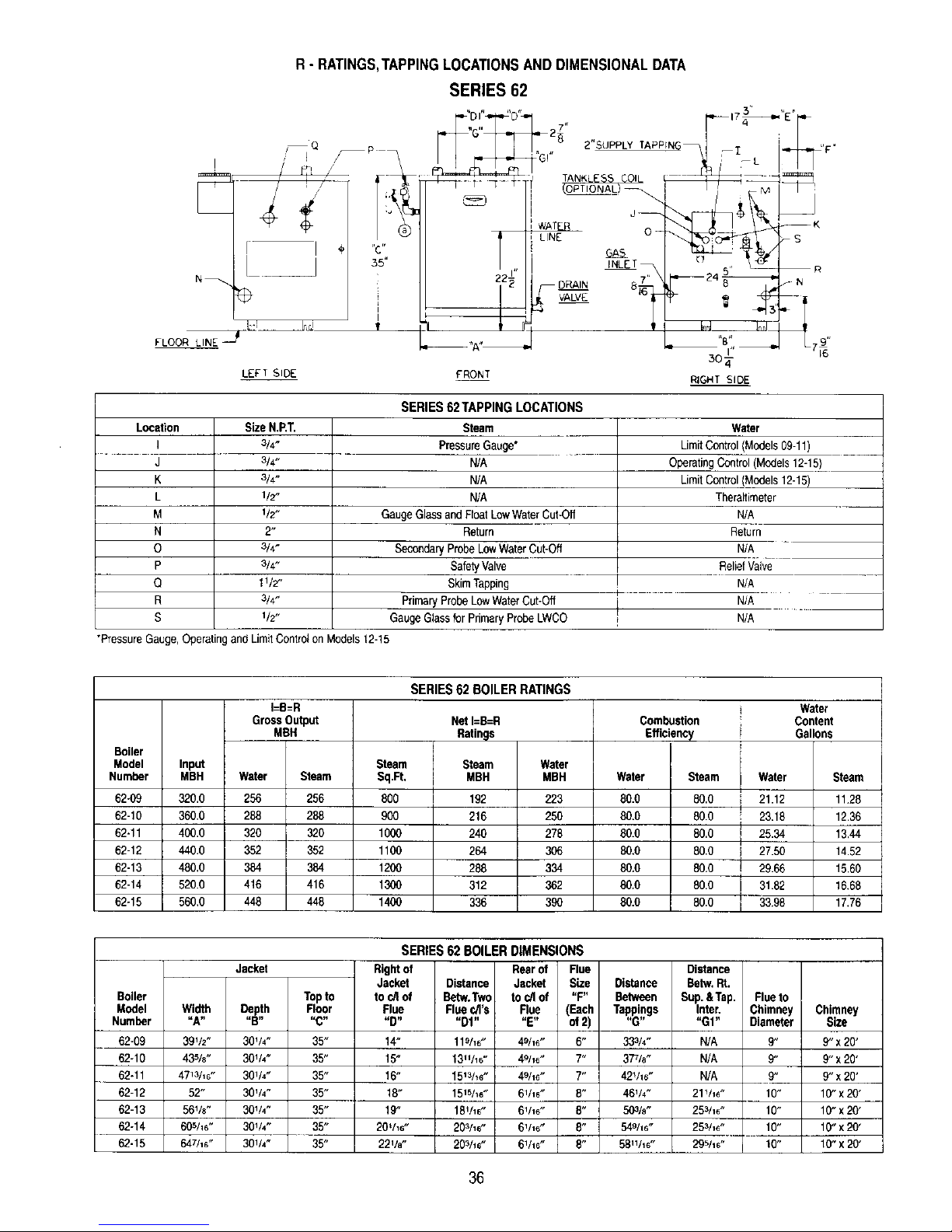
R- RATINGS,TAPPINGLOCATIONSANDDIMENSIONALDATA
SERIES 62
N_
÷
FLOOR LINE_I-LI_4!
LEFT SIDE
,,mr,
35"
"DI.... [ ,, 17_"E"
"G" 27
#'G'" TL,_ Fr
/
/ ,,/ I_LET_ _ .5' 'kff_ r_
I I VALVE 161_ _ ,_ _b_ -|
J
_'A'_' _ BI,, _ LYe'
FRONT RIGHT SIDE
Location
I
J
K
L
M
N
O
P
Q
R
S
SizeN.RT.
3/4.
3/4.
3/4"
1/2"
1/2"
2"
3/4-
3/4"
11/2"
3/4-
1/2"
SERIES 62 TAPPING LOCATIONS
Steam
PressureGauge*
N/A
N/A
N/A
GaugeGlassandFloatLowWaterCut-Off
Return
SecondaryProbeLowWaterCut-off
SafetyValve
SkimTapping
PrimaryProbeLowWaterCut-off
GaugeGlassfor PrimaryProbe LWCO
"PressureGauge, Operatingand LimitControlon Models12-15
Water
LimitControl/Models09-11)
OperatingControl(Models12-16)
LimitControl(Models12-15)
Theraltimeter
N/A
Return
N/A
ReliefValve
N/A
N/A
N/A
Boiler
Model Input
Number MBH
62-09 320.0
62-10 360.0
62-11 400.0
62-12 440.0
62-13 480.0
62-14 520.0
62-15 560,0
I=B=R
GrossOutput
MBH
Water Steam
256 256
288 288
320 320
352 352
384 384
416 416
448 446
SERIES62 BOILERRATINGS
Net I=B=R
Ratings
Steam Steam Water
Sq.Ft, MBH MBH
800 192 223
900 216 250
1000 240 278
1100 264 306
1200 288 334
1309 312 362
1400 336 390
Combustion
Efficiency
Water Steam
80.0 80.0
80.0 80.0
80.0 80.0
80.0 80.0
80.0 80.0
80.0 80.0
80.0 80.0
i
Water
21.12
23.18
25.34
j 27.60
J 29.66
i 3182
j 3398
Water
Content
Gallons
Steam
11.28
12.36
13.44
14.52
15.60
16.68
17#6
Boger
Model
Number
62-09
62-10
62-11
62-12
62-13
62-14
62-15
Width
uA-
39V2"
435/8"
4713/16"
52"
561/8"
605h6"
647/1s"
Jacket
Depth
"B"
301/4"
30114"
301h"
301/4"
30V4"
30V4"
30V4"
Topto
SERGES62 BOILER DIMENSIONS
Rightof Rearof Flue
Jacket Distance Jacket Size
to c/Iof Betw.Tw¢ to cffof "F"
Floor Flue
"C" "D"
35" t4"
35" 15"
35" 16"
35" 18"
35" 19"
35" 20'h6"
35" 22Ve"
Distance
Between
Flea c/l'e Rue (Each Tappings
"D1.... E" of2)
"G"
119h6" 49/16" 6" 33314"
1311116" 49/1e" 7" 37_/e"
15_3h6" 49116" 7" 42V16"
151She" 6V16" 8" 46V4"
18V_e" 6V_6" 8" 50316"
20_he" 6V_6" 8" 549h6"
203/16" 61116" 6" 5811116"
Distance
Betw.Rt.
Sup.&Tap. Flueto
Inter. Chimney Chimney
"Gt" Diameter Size
N/A 9" 9" x 20'
N/A 9" 9" x 20'
N/A 9" 9" x 20'
21V_6" 10" 10" x20'
253h6" 10" 10" x20'
253h6" 10" 10"x 20'
295h6" I0" I0" x 20'
36
Page 45

S - MAINTENANCE AND INSPECTION
1--This boilermustbe disconnectedfromthe gassupplypipingduringanypressuretestingof thesystem.RefertoSectionH- "GASPIPING".
Note8 for details.
2--The gasventusedonthis boi{erisofthehorizontalto verticaltype.Thevent andventingsystemshouldbeinspectedthoroughlyat the
beginningof eachheatingsystem.
3--The areawherethe boileriscontainedshould beclearand free fromcombustiblematerials,gasolineandotherflammablevaporsand liquids.
Theboilerarea shouldhaveampleair for combustionandventilationand thereshouldbeno obstructionspreventingafreeflow of air
4--AI1low watercut-offsshouldbetestedand inspectedper manufacturer'sinstructions,anyfloattypesshouldbeflushed onaweeklybasisto
removeanysedimentfromthefloat bowl.
5--A visualcheck ofburnerandpilotflameshouldbe conductedatleastoncea year.Theflame interconeshouldbe approximately11/2inches
high andshouldhaveavery sharp,bfuecolorcharacteristic.SeeFigurebelow.
m w
f
f
/ \
/ \
\ /
\ J
f
6--At the beginningofeachheatingseason,fluewaysandburnersshouldbecheckedforcleanlinessandcleanedifnecessary.Followingprocedure
wouldapplyifcleaningisrequired.
a. Turnoftallelectricalpowerto boilerbeforebeginningcleaningoperation.FollowLighting/OperatingInstructionsforshuttingoff
maingasto appliance.
b. Removetheflue pipe,drafthood,top jacketpanelsand flue collector.
c. Brushfluewayswithwirebrush.
d. Replacefluecollector.Whenreplacingthe flue collector,be certainthat the sealingropebetweenthe flue collectorandtop section
makesa tightseal topreventleakageofthe productsofcombustion.
e. Replacethetop of jacket,drafthoodand fluepipe.
f. Removethejacketclean-outcoverplate.SeeFigure4.
g. Removecastironcover plateby removingfour(4) capscrewsat thecornersof theplate.
h. Brushtubeswith wire brush.
i. Replacecoverplates.MakesureHi Tempropegasketis in place.
j. Removefrontjacketpanel(Figure4),and burneraccesscoverdoor(Figure11).
k. Removeburnersandbrushgasoutletports lightlyusingsoft bristlebrush.
I. Replaceburners(SeeFigure12)and alljacketpanels.
m. FollowLighting/OperatingInstructionsforputtingboilerintooperation.
37
Page 46

REPAIR PARTS
SERIES 61/62 GAS BOILERS
REPAIR PARTS ARE AVAILABLEFROMYOUR INSTALLER OR BY CONTACTING
PEERLESS HEATER COMPANY,BOYERTOWN,PA 19512-0855
NOTE: REMEMBERTO INCLUDE BOILER MODEL NUMBER AND SERIAL NUMBER WHEN ORDERING PARTS.
ItemNo. Description AdditionalInformation
t IntermediateSection
2 Left HandEndSection
3 RightHandEndSection
4
5
6
7
8
9
10
11
12
13
14
15
16
17
18
19
20
21
22
23
24
25
26
27
28
Part No.
P-150
P-151
P-152
P-152C
P-154
12-EF
64
P-162
P-161
P-158
P-120
P-106
X-1037
X-1023
X-1034
P-155
P-156
X-1009
X-1001
P-4208
P-4209
P-4210
X-4003
X-3005
P-503
P-504
TappedIntermediateSection
PushNipple
PushNipple
5/8"HighTemperatureRope
CompleteBlockAssembly
LeftHandBlockAssembly
RightHandBlockAssembly
DrawRodsw/nutsandwashers
CleanOutCoverPlate
1/4"HighTemperatureRope
TanklessHeaterFlangew/screws
RubberGasket
CoverPlatew/screws
BaseBack
BaseBack
Draw-UpWasher
Draw-UpWasher
3/4"GasManifold
1" GasManifold
11/4"GasManifoldfor 62-15
OrificeSpud
SteelBurnerw/pilotbracket
SteelBurner
ThrottlingPilotCock
FlueCollector
DraftHood
50 lb.WorkingPressure
50 lb.WorkingPressure
w/CoilOpening
w/Cast ClosedCoilOpening
50 lb.WorkingPressure
1 RequiredPerFlueway
1 RequiredPerFlueway
42"RequiredPerFlueway
SpecifyBoilerModel
SpecifyBoilerModel
SpecifyBoilerModel
SpecifyBoilerModel
44"RequiredFor P-106
SpecifyBoilerModel
SpecifyBoilerModeland Rightor Left Side
2 Required
2 Required
SpecifyBoilerModel
SpecifyBoilerModel
SpecifyQuantify,Typeof Gas,BoilerModelandAltitude
SpecifyControlSystem
SpecifyQuantity
SpecifyBoilerModel
SpecifyBoilerModel
38
Page 47
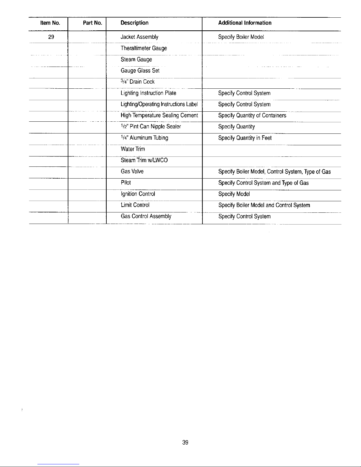
ItemNo, PartNo. Description
29
JacketAssembly
TheraltimeterGauge
SteamGauge
Gauge GlassBet
3/4"DrainCock
LightingInstructionPlate
Lighting/OperatingInstructionsLabel
HighTemperatureSealingCement
1/2"PintCanNippleSealer
1/4"AluminumTubing
WaterTrim
SteamTrimw/LWCO
GasValve
Pilot
IgnitionControl
LimitControl
GasControlAssembly
AdditionalInformation
SpecifyBoilerModel
SpecifyControlSystem
SpecifyControlSystem
SpecifyQuantityof Containers
SpecifyQuantity
SpecifyQuantityinFeet
SpecifyBoilerModel,ControlSystem,Typeof Gas
SpecifyControlSystemandTypeof Gas
SpecifyModel
SpecifyBoilerModelandControlSystem
SpecifyControlSystem
39
Page 48

Series 61/62
Gas
Boilers
Installation,
Operation Et
Maintenance
Manual
TO THE INSTALLER:
This manual is the property of the owner and must
be affixed near the boiler for future reference.
TO THE OWNER:
This boiler should be inspected annually by a
Qualified Service Agency.
HI Division ASME
af gama
PEERLESS BOILERS
www.peerless-heater.com
@2003 Peerless Heater Company P8207 R23 (3/03-2,5M)
Printed in U.SA.
 Loading...