

Page 1
Great Plains Mfg., Inc.
Installation Instructions
6 Foot Drill
Seed Box Agitator Option
Used with:
• 605NT
• 3P605NT
• 3P600
General Information
When you see this symbol, the subsequent instructions and
warnings are serious - follow without exception. Your life and
!
!
the lives of others depend on it!
These instructions explain how to install the agitator option. The agitator stirs the seed directly
above the metering cups. It is intended to cut
down on the "bridging" of light fluffy seeds.
These instructions apply to:
118-748A 3P600 Agitator w/Drive - 7-1/2"
118-749A 3P600 Agitator w/o Drive - 7-1/2"
118-750A 3P605NT & 605NT Agitator
w/Drive
118-751A 3P605NT & 605NT Agitator w/o
Drive
118-788A 3P600 Agitator w/Drive - 6"
118-789A 3P600 Agitator w/o Drive - 6"
Manual Update
Refer to the 6 foot drill operator’s manual for detailed information on safely operating, adjusting,
troubleshooting and maintaining the agitator option. Refer to the parts manual for part
identification.
Drill Manual Part Numbers
151-061M 605NT & 3P605NT Operator’s
Manual
151-061P 605NT & 3P605NT Parts Manual
118-794M 3P600 Operator’s Man ual
118-794P 3P600 Parts Manual
Before You Start
Beginning on page 8 are detailed listings of parts
included in the agitator option packages . Use the
proper list to inventory parts received.
Definitions
Right-hand and left-hand as used in this manual
are determined by facing the direction the machine will travel while in use unless otherwise
stated.
Assembly Instructions
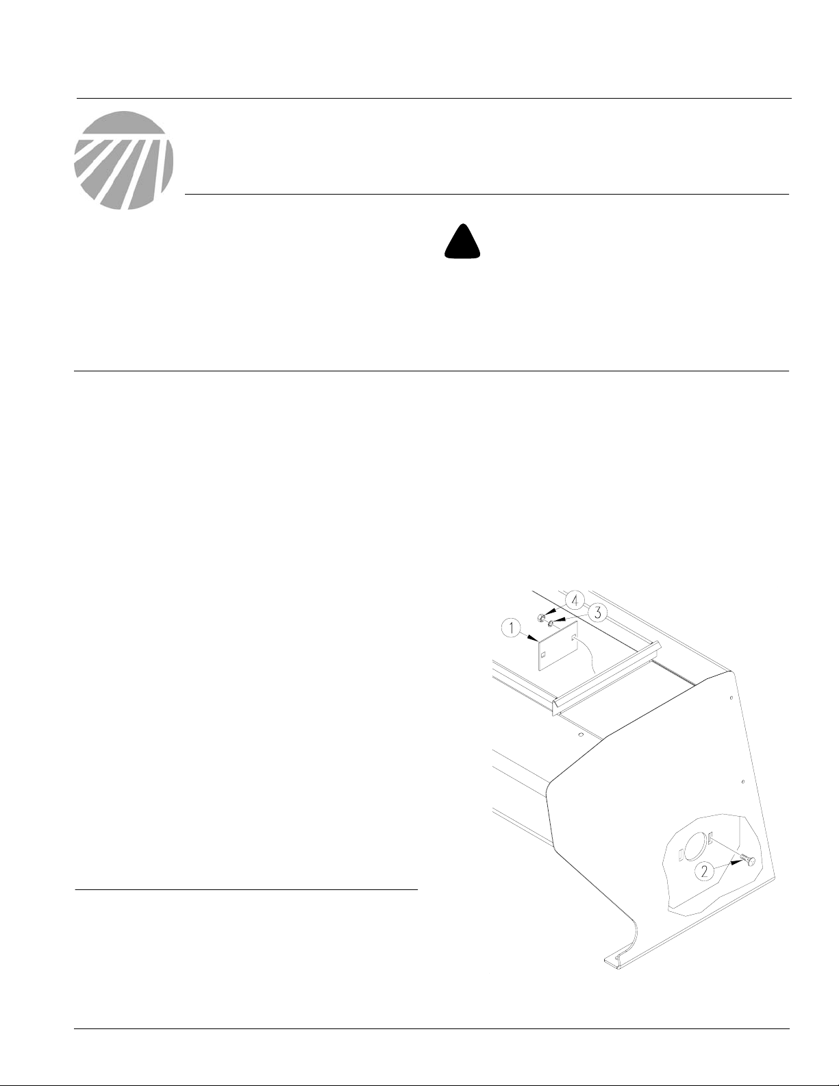
Agitator Shaft
See
Figure 1:
1. Remove cov ers (1) from inside both ends of
seed box by removing bolt (2), loc k washer (3)
and hex nut (4).
© Copyright 2000 Printed
4/26/2000
18726
Figure 1
Seed Box Cover Removal
151-071M
Page 2
Seed Box Agitator Option
2
Great Plains Mfg., Inc.
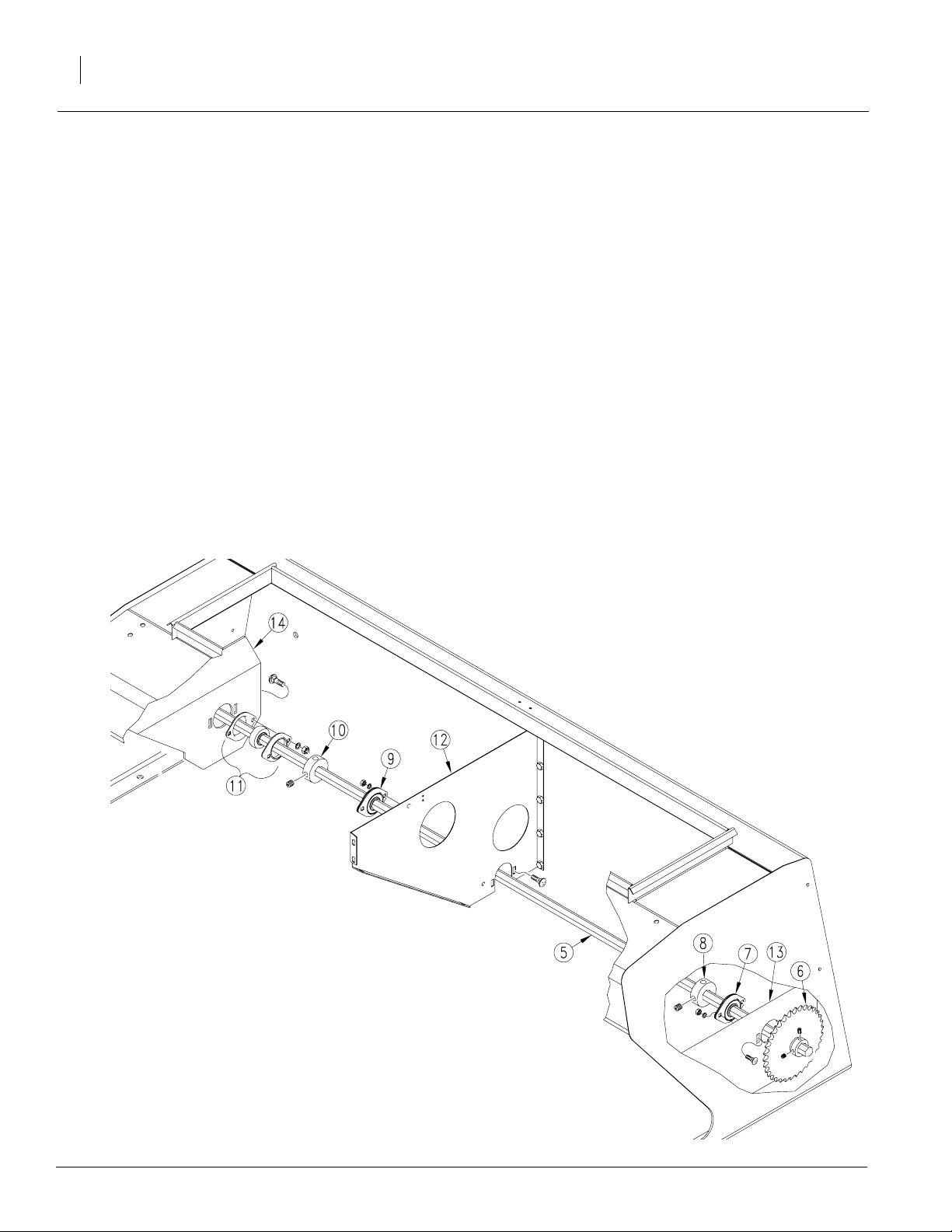
See
Figure 2:
2. Slide agitator shaft (5) into seed box from left
side of drill.
3. As shaft advances, slide on parts in the following order.
• 35 tooth sprocket (6)
• bearing and flanges (7)
• lock collar (8)
• bearing and flanges (9)
• lock collar (10)
• bearing and flanges (11)
4. Attach bearings and flanges to divider (12)
and inside of end panels (13 and 14) with 5/16
x 1 inch round head bolts, lock washers and
hex nuts.
5. Slide lock collars (8 and 10) against bearing
and flanges (7 and 11) and tighten set
screws.
Figure 2
Agitator shaft Installation
151-071M 3/31/2004
18727
Page 3
Great Plains Mfg., Inc.
Drive Assembly
605NT and 3P605NT Drive
NOTE: If your drill is equipped with a nativ e grass
option, a majority of the agitator drive is already
installed. Go to
See
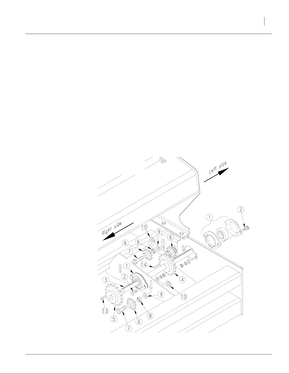
Figure 3:
1. Mount bearings and flanges (1) to left side of
drill frame and to the frame support as shown.
Use 5/16 x 1 inch bolts (2), washers and nuts
to secure flanges. Leave bolts loose .
2. Install drive shaft (3) through bearings. As you
install shaft, place 17 tooth sprocket (4) on
shaft near left side of drill frame.
3. Place 17 tooth sprocket (5) on the right end of
shaft.
4. Install three 12 tooth idler sprockets (6) in locations shown, using a 1/2 x 3-1/2 inch bolts
(7), hex jam nuts (8), USS flat washers (9)
and hex flange nuts (10).
page 4 for chain routing.
Installation Instructions
3
3/31/2004
18662
Figure 3
605NT & 3P605NT Drive Assembly
151-071M
Page 4
Seed Box Agitator Option
4
Great Plains Mfg., Inc.
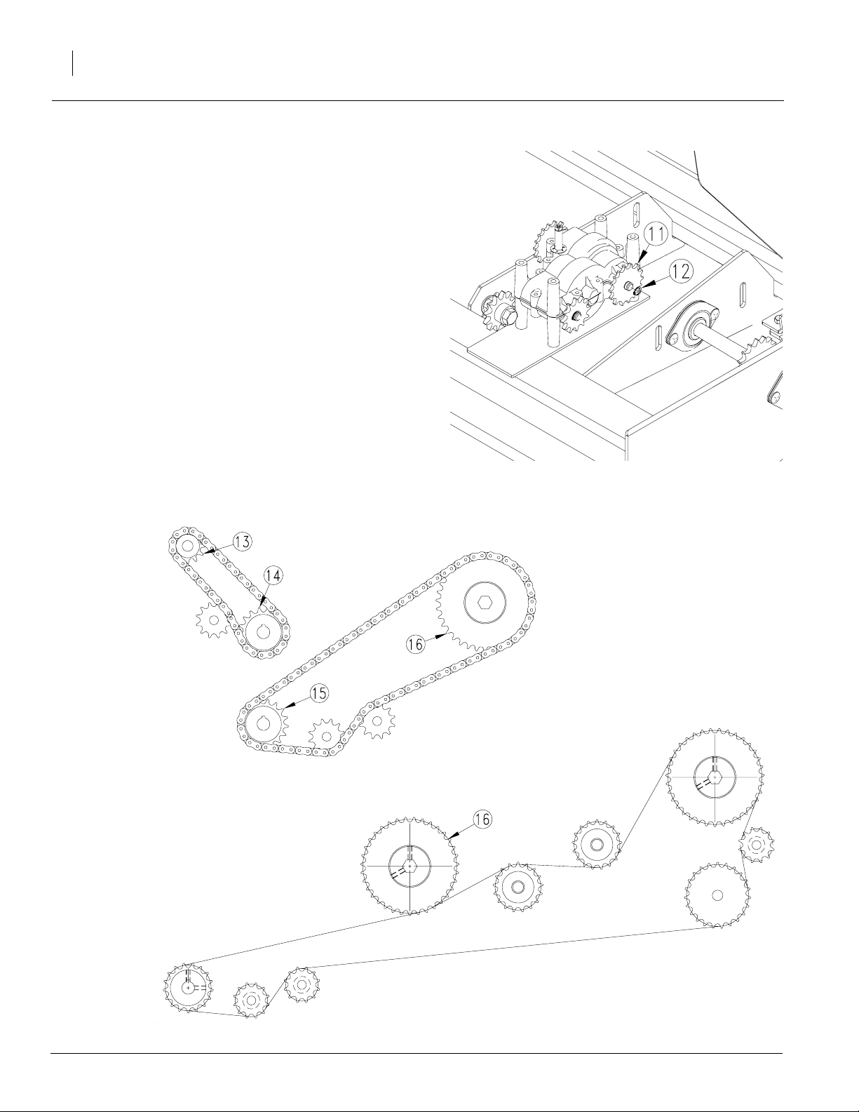
5. Refer to Figure 4.
Install 16 tooth splined
sprocket (11) to gearbo x as sho wn, and fasten with snap ring (12).
See
Figure 5:
6. Route chains as follows:
a. The 45 pitch chain around new 16 tooth
sprocket (13) on gearbo x to 17 tooth
sprocket (14).
b. The 89 pitch chain around 17 tooth
sprocket (15) near left side of frame to 35
tooth sprocket (16) on agitator shaft.
7. Adjust idlers to remove chain slack.
Figure 4
Gearbox Sprocket
18728
Agitator Chain Routing
NOTE: F or drills with the native grass
option, include the agitator sprocket
(16) in the 166 pitch chain routing as
shown.
Agitator Chain Routing with Native Grass
Figure 5
151-071M 3/31/2004
18730
Page 5

Great Plains Mfg., Inc.
3P600 Drive
See
Figure 6:
1. Mount bearing and flanges (1) inside end
panels of drill frame. Use 5/16 x 1 inch bolts
(2), washers and nuts to secure flanges.
Leave bolts loose.
2. Install drive shaft (3) through bearings. As you
install shaft, place 22 tooth sprocket (4) on
shaft to the left of gearbox.
3. Place 17 tooth sprocket (5) on shaft near the
left drill frame end panel.
4. Place 12 tooth splined sprocket (6) on left
front gearbox shaft. Secure with snap ring (7).
5. Align shaft and tighten flange bolts. Align
sprockets (4 and 5). Secure with ke ys (8 and
9).
Installation Instructions
5
3P600 Drive w/Small Seeds Option
If your drill is equipped with a small seeds option,
a majority of the agitator drive is already installed.
Refer to Figure 6:
• Place 17 tooth sprocket (5) near left drill
frame end panel.
• Align sprocket and secure with key (9).
• Go to step 7b on page 6.
3/31/2004
Figure 6
3P600 Drive Assembly
18728
151-071M
Page 6

Seed Box Agitator Option
6
See
Figure 7:
6. Install two 12 tooth idler sprockets (10) in locations shown, using 1/2 x 3 1/2 inch bolts
(11), hex jam nuts (12), USS flat washers (13)
and hex flange nuts (14).
See
Figure 8:
7. Route chains as follows:
a. The 63 pitch chain around new 12 tooth
sprocket (15) on gearbo x to 22 tooth
sprocket (16).
b. The 68 pitch chain around 17 tooth
sprocket (17) near left side of frame to 35
tooth sprocket (18) on agitator shaft.
8. Adjust idlers to remove chain slack.
Figure 7
Idler Installation
Great Plains Mfg., Inc.
18731
Figure 8
3P600 Chain Routing
151-071M 3/31/2004
18732
Page 7

Great Plains Mfg., Inc.
Agitator Paddle Installation
See
Figure 9:
1. Place an agitator paddle (1) over the he x shaft
directly above a f eeder cup. Position paddle
as shown (paddle 1).
2. Slip a 1/4 x 2 inch hex flange bolt (2) through
the paddle and secure with a hex flange lock
nut (3).
NOTE: Bef ore tightening a paddle or group of
paddles, carefully rotate the drive system to make
sure paddles do not hit the tray dividers.
3. Place a paddle over the ne xt feeder cup. Ro-
tate this paddle 1/6th of a turn and slide it onto
the next set of flats as shown (paddle 2).
4. Continue the installation above each f eeder
cup, rotating the paddle 1/6th of a turn each
time as shown ( paddles 3 through 6).
Installation Instructions
5. Start over with paddle 1 and continue until
each feeder cup has a paddle. The fully assembled shaft will have a spir al result.
6. After checking for interf erence, torque the
paddle bolts to 9 ft. lbs. (108 in lbs.)
paddle 1
7
paddle 2
paddle 3
paddle 4
paddle 5
3/31/2004
Figure 9
Agitator Paddle Assembly
paddle 6
18739
151-071M
Page 8

Seed Box Agitator Option
8
118-748A 3P600 AGITATOR ASSY W/DRIVE - 7-1/2"
Your kit includes:
Qty. Part No. Part Description
9 118-493D AGITATOR PADDLE 3/4 HEX
2 118-494D LOCK COLLAR 3/4 HEX BORE
1 118-498D SEED FLOAT DOWN FLOAT STOP
1 118-556D 6’ DRILL AGITATOR SHAFT
1 133-037D SGS/AUXILLARY DRIVE SHAFT
1 136-065D CHAIN RL #40 63 PITCHES
1 136-111D CHAIN RL #40 68 PITCHES
2 168-127D 3/16 X 1 KEY
1 800-141C SNAP RING EXT F/PEERLESS G.B.
4 801-035C SCREW SET 5/16-18 SKT KP X 3/8
2 802-039C HHCS 1/2-13X3 GR5
10 802-282C RHSNB 5/16-18X1 GR5
9 802-448C HFSS 1/4-20X2 GR5
10 803-008C NUT HEX 5/16-18 PLT
2 803-036C NUT HEX JAM 1/2-13PPLT
9 803-088C NUT HEX LOCK 1/4-20 FLG
2 803-169C NUT HEX FLG. LOCK 1/2-13 PLT.
10 804-009C WASHER LOCK SPRING 5/16 PLT
4 804-017C WASHER FLAT 1/2 USS PLT
1 808-100C SPROCKET 40B22 3/4B W/K.W. &SS
1 808-160C SPKT 40B12 X 36T SPLINE BORE
1 808-170C SPKT 40B17 X 3/4BORE W/KW&SS
1 808-185C SPKT 40B35 X 3/4 HEX BORE
2 817-025C NO. 40 12T IDLER SPKT.
2 822-040C BEARING 3/4BORE 47MM SPHERE OD
10 822-041C FLANGETTE 47 MST
3 822-128C BEARING 3/4HEX B 47MM SPHER OD
Great Plains Mfg., Inc.
3/31/2004
151-071M
Page 9

Great Plains Mfg., Inc.
118-750A 605NT & 3P605NT AGITATOR ASSY W/DRIVE
Your kit includes:
Qty. Part No. Part Description
9 118-493D AGITATOR PADDLE 3/4 HEX
2 118-494D LOCK COLLAR 3/4 HEX BORE
1 118-498D SEED FLOAT DOWN FLOAT STOP
1 118-556D 6’ DRILL AGITATOR SHAFT
1 202-182D AUXILLARY DRIVE SHAFT
1 136-054D CHAIN RL #40 89 PITCHES
1 136-161D CHAIN RL #40 45 PITCHES
1 168-127D 3/16 X 1 KEY
1 800-141C SNAP RING EXT F/PEERLESS G.B.
4 801-035C SCREW SET 5/16-18 SKT KP X 3/8
3 802-039C HHCS 1/2-13X3 GR5
10 802-282C RHSNB 5/16-18X1 GR5
9 802-448C HFSS 1/4-20X2 GR5
10 803-008C NUT HEX 5/16-18 PLT
3 803-036C NUT HEX JAM 1/2-13 PLT
9 803-088C NUT HEX LOCK 1/4-20 FLG
3 803-169C NUT HEX FLG. LOCK 1/2-13 PLT.
10 804-009C WASHER LOCK SPRING 5/16 PLT
3 804-017C WASHER FLAT 1/2 USS PLT
2 808-170C SPKT 40B17 X 3/4BORE W/KW&SS
1 808-185C SPKT 40B35 X 3/4 HEX BORE
1 808-271C SPKT 40B16 X 36T SPLINE BORE
3 817-025C NO. 40 12T IDLER SPKT.
2 822-040C BEARING 3/4BORE 47MM SPHERE OD
10 822-041C FLANGETTE 47 MST
3 822-128C BEARING 3/4HEX B 47MM SPHER OD
Installation Instructions
9
151-071M3/31/2004
Page 10

Seed Box Agitator Option
10
118-749A 3P600 AGITATOR ASSY WITHOUT DRIVE - 7-1/2"
Your kit includes:
Qty. Part No. Part Description
9 118-493D AGITATOR PADDLE 3/4 HEX
2 118-494D LOCK COLLAR 3/4 HEX BORE
1 118-498D SEED FLOAT DOWN FLOAT STOP
1 118-556D 6’ DRILL AGITATOR SHAFT
1 136-111D CHAIN RL #40 68 PITCHES
1 168-127D 3/16 X 1 KEY
4 801-035C SCREW SET 5/16-18 SKT KP X 3/8
1 802-039C HHCS 1/2-13X3 GR5
6 802-282C RHSNB 5/16-18X1 GR5
9 802-448C HFSS 1/4-20X2 GR5
6 803-008C NUT HEX 5/16-18 PLT
1 803-036C NUT HEX JAM 1/2-13 PLT
9 803-088C NUT HEX LOCK 1/4-20 FLG
1 803-169C NUT HEX FLG. LOCK 1/2-13 PLT.
6 804-009C WASHER LOCK SPRING 5/16 PLT
2 804-017C WASHER FLAT 1/2 USS PLT
1 808-170C SPKT 40B17 X 3/4BORE W/KW&SS
1 808-185C SPKT 40B35 X 3/4 HEX BORE
1 817-025C NO. 40 12T IDLER SPKT.
6 822-041C FLANGETTE 47 MST
3 822-128C BEARING 3/4HEX B 47MM SPHER OD
Great Plains Mfg., Inc.
118-751A 605NT & 3P605NT AGITATOR ASSY WITHOUT DRIVE
Your kit includes:
Qty. Part No. Part Description
9 118-493D AGITATOR PADDLE 3/4 HEX
2 118-494D LOCK COLLAR 3/4 HEX BORE
1 118-498D SEED FLOAT DOWN FLOAT STOP
1 118-556D 6’ DRILL AGITATOR SHAFT
1 136-054D CHAIN RL #40 89 PITCHES
1 168-127D 3/16 X 1 KEY
4 801-035C SCREW SET 5/16-18 SKT KP X 3/8
2 802-039C HHCS 1/2-13X3 GR5
6 802-282C RHSNB 5/16-18X1 GR5
9 802-448C HFSS 1/4-20X2 GR5
6 803-008C NUT HEX 5/16-18 PLT
2 803-036C NUT HEX JAM 1/2-13 PLT
9 803-088C NUT HEX LOCK 1/4-20 FLG
2 803-169C NUT HEX FLG. LOCK 1/2-13 PLT.
6 804-009C WASHER LOCK SPRING 5/16 PLT
2 804-017C WASHER FLAT 1/2 USS PLT
1 808-170C SPKT 40B17 X 3/4BORE W/KW&SS
1 808-185C SPKT 40B35 X 3/4 HEX BORE
2 817-025C NO. 40 12T IDLER SPKT.
6 822-041C FLANGETTE 47 MST
3 822-128C BEARING 3/4HEX B 47MM SPHER OD
3/31/2004
151-071M
Page 11

Great Plains Mfg., Inc.
118-788A 3P600 AGITATOR ASSY W/DRIVE - 6"
Your kit includes:
Qty. Part No. Part Description
11 118-493D AGITATOR PADDLE 3/4 HEX
2 118-494D LOCK COLLAR 3/4 HEX BORE
1 118-498D SEED FLOAT DOWN FLOAT STOP
1 118-556D 6’ DRILL ADGITATOR SHAFT
1 133-037D SGS/AUXILLARY DRIVE SHAFT
1 136-104D CHAIN RL #40 62 PITCHES
1 136-111D CHAIN RL #40 68 PITCHES
2 168-127D 3/16 X 1 KEY
1 800-141C SNAP RING EXT F/PEERLESS G.B.
4 801-035C SCREW SET 5/16-18 SKT KP X 3/8
2 802-039C HHCS 1/2-13X3 GR5
10 802-282C RHSNB 5/16-18X1 GR5
11 802-448C HFSS 1/4-20X2 GR5
10 803-008C NUT HEX 5/16-18 PLT
2 803-036C NUT HEX JAM 1/2-13GPLT
11 803-088C NUT HEX LOCK 1/4-20 FLG
2 803-169C NUT HEX FLG. LOCK 1/2-13 PLT.
10 804-009C WASHER LOCK SPRING 5/16 PLT
4 804-017C WASHER FLAT 1/2 USS PLT
1 808-100C SPKT 40B22 3/4B W/K.W. &SS
1 808-160C SPKT 40B12 X 36T SPLINE BORE
1 808-170C SPKT 40B17 X 3/4BORE W/KW&SS
1 808-185C SPKT 40B35 X 3/4 HEX BORE
2 817-025C NO. 40 12T IDLER SPKT.
2 822-040C BEARING 3/4BORE 47MM SPHERE
10 822-041C FLANGETTE 47 MST
3 822-128C BEARING 3/4HEX B 47MM SPHER OD
Installation Instructions
11
151-071M3/31/2004
Page 12

Seed Box Agitator Option
12
118-789A 3P600 AGITATOR ASSY WITHOUT DRIVE - 6"
Your kit includes:
Qty. Part No. Part Description
11 118-493D AGITATOR PADDLE 3/4 HEX
2 118-494D LOCK COLLAR 3/4 HEX BORE
1 118-498D SEED FLOAT DOWN FLOAT STOP
1 118-556D 6’ DRILL AGITATOR SHAFT
1 136-111D CHAIN RL #40 68 PITCHES
1 168-127D 3/16 X 1 KEY
4 801-035C SCREW SET 5/16-18 SKT KP X 3/8
1 802-039C HHCS 1/2-13X3 GR5
6 802-282C RHSNB 5/16-18X1 GR5
11 802-448C HFSS 1/4-20X2 GR5
6 803-008C NUT HEX 5/16-18 PLT
1 803-036C NUT HEX JAM 1/2-13 PLT
11 803-088C NUT HEX LOCK 1/4-20 FLG
1 803-169C NUT HEX FLG. LOCK 1/2-13 PLT.
6 804-009C WASHER LOCK SPRING 5/16 PLT
2 804-017C WASHER FLAT 1/2 USS PLT
1 808-170C SPKT 40B17 X 3/4BORE W/KW&SS
1 808-185C SPKT 40B35 X 3/4 HEX BORE
1 817-025C NO. 40 12T IDLER SPKT.
6 822-041C FLANGETTE 47 MST
3 822-128C BEARING 3/4HEX B 47MM SPHER OD
Great Plains Mfg., Inc.
3/31/2004
151-071M
 Loading...