

Page 1
TECHNICAL SUPPORT 1-800-787-5020 ext 275
®
TECHNICAL SUPPORT 1-800-787-5020 ext 275
®
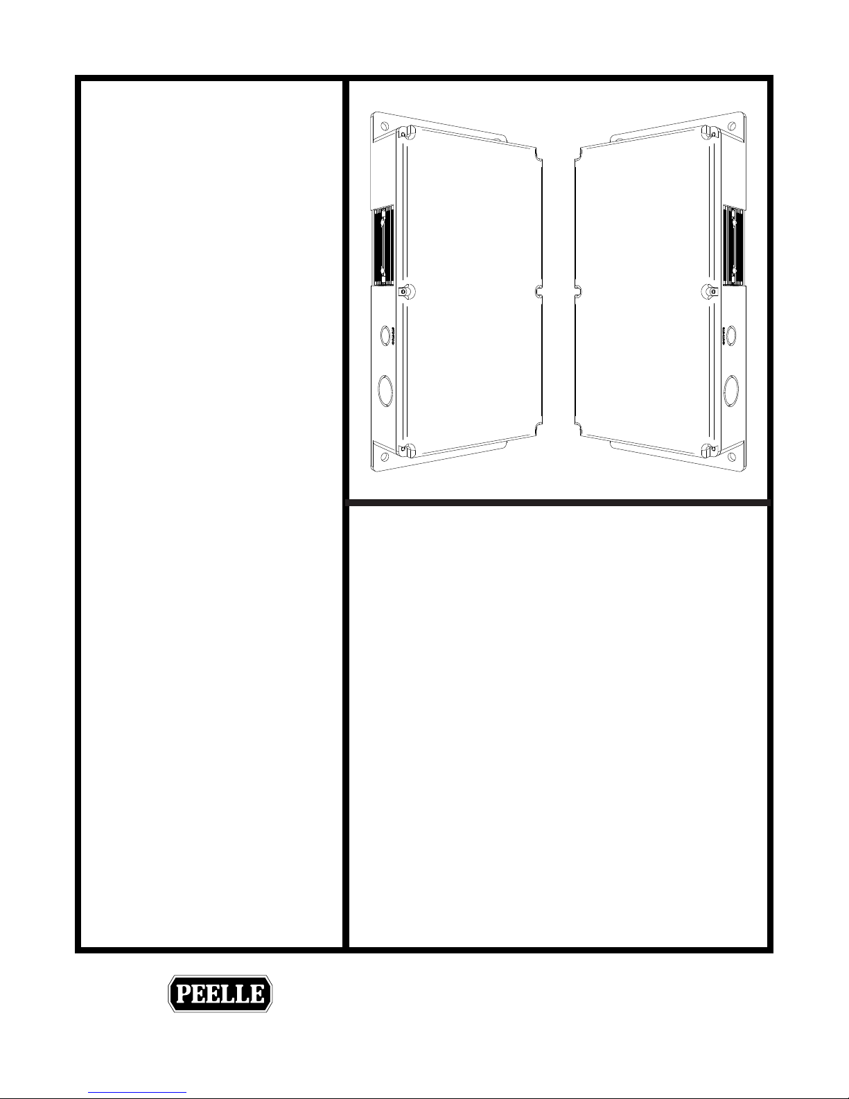
WIRELESS CONTROLLER
& BRIDGE
INSTALLATION &
INTERFACE GUIDE
254-EN
THE PEELLE COMPANY
THE PEELLE COMPANY
FREIGHT DOORSICAR GATESICAR ENCLOSURES
FREIGHT DOORSICAR GATESICAR ENCLOSURES
Guide No.
VERSION:
WIRELESS CONTROLLER & BRIDGE
INSTALLATION & INTERFACE GUIDE
Date:
Mar 07 / 2018
254-EN
Page 2

Page 3

TECHNICAL SUPPORT 1-800-787-5020 ext 275
®
Contents
1.0 SAFETY WARNING 1
2.0 LANDING DOOR CONTROLLER INSTALLATION 2
2.1 LANDING DOOR CONTROLLER MOUNTING 2
2.2 LANDING DOOR WIRING LAYOUT - STANDARD OPERATORS (OPTION) 3
2.3 LANDING DOOR WIRING LAYOUT - EXTRA HIGH TORQUE OPERATORS 4
2.4 LANDING DOOR POWER CONNECTIONS 5
2.5 LANDING DOOR ENCODER 6
2.6 LANDING DOOR OPERATORS - STANDARD OPERATORS 7
2.7 LANDING DOOR OPERATORS - EXTRA HIGH TORQUE (OPTION) 8
2.8 LANDING DOOR EMERGENCY UNLOCKING DEVICE (EUD) 9
2.9 LANDING DOOR ZONE SWITCH (ZNS) 10
2.10 LANDING DOOR HALL PUSHBUTTONS 11
2.11 LANDING DOOR LIGHT CURTAIN (OPTIONAL) 12
3.0 CAR DOOR (GATE) CONTROLLER INSTALLATION 13
3.1 CAR DOOR LOCATION AND WIRING LAYOUT 13
3.2 CAR DOOR POWER CONNECTIONS 14
3.3 CAR DOOR ENCODER 15
3.4 CAR DOOR (GATE) OPERATOR 16
3.5 RETIRING CAM MOTOR 17
3.6 CAR DOOR REVERSING EDGE (OPTIONAL) 18
3.7 SINGLE LIGHT CURTAIN (OPTION) 19
3.8 DUAL LIGHT CURTAINS (OPTION) 20
3.9 WARNING BUZZER 21
3.10 CAR STATION DOOR PUSHBUTTONS 22
4.0 BRIDGE CONTROLLER INSTALLATION 23
4.1 BRIDGE CONTROLLER LOCATION AND WIRING LAYOUT 23
4.2 BRIDGE POWER CONNECTIONS 24
4.3 BRIDGE TO CAR DOOR CONNECTION 25
4.4 ELEVATOR TO BRIDGE CONTROLLER INPUT CONNECTIONS 26
4.5 BRIDGE CONTROLLER TO ELEVATOR OUTPUT CONNECTIONS 28
Guide No.
THE PEELLE COMPANY
FREIGHT DOORSICAR GATESICAR ENCLOSURES
VERSION:
WIRELESS CONTROLLER & BRIDGE
INSTALLATION & INTERFACE GUIDE
254-EN
Date:
Mar 07 / 2018
Page 4

TECHNICAL SUPPORT 1-800-787-5020 ext 275
®
5.0 COMMISSIONING 29
5.1 CAR DOOR COMMISSIONING 29
5.2 LANDING DOOR COMMISSIONING 31
5.3 OPERATION AND TESTING - FROM THE CAR DOOR CONTROLLER 32
5.4 SEQUENCE OF OPERATION 32
5.5 POWER UP MODE / LOSS OF POWER 32
5.6 BRIDGE COMMISSIONING 33
5.7 LANDING AND CAR DOOR INTERLOCKING CIRCUITS 34
6.0 CONTROLLER SETTINGS 35
6.1 DOOR MOTION PROFILES 35
6.2 CAR & LANDING DOOR CONTROLLER PARAMETERS 35
6.3 BRIDGE CONTROLLER PARAMETERS 38
7.0 TROUBLESHOOTING 39
7.1 INDEPENDENT MODE 39
7.2 AUTOMATIC MODE 40
7.3 ELEVATOR INTERFACE OPERATION 41
7.4 ERROR CODES 42
7.5 LANDING DOOR LCD 43
7.6 CAR DOOR LCD 44
7.7 BRIDGE LCD 45
8.0 TECHNICAL SPECIFICATIONS 46
9.0 EC DECLARATION OF CONFORMITY 47
THE PEELLE COMPANY
FREIGHT DOORSICAR GATESICAR ENCLOSURES
Guide No.
254-EN
VERSION:
WIRELESS CONTROLLER & BRIDGE
INSTALLATION & INTERFACE GUIDE
Date:
Mar 07 / 2018
Page 5
TECHNICAL SUPPORT 1-800-787-5020 ext 275
®
1.0 SAFETY WARNING
T&B Conduit Fittings
Rigid and Intermediate Metal Conduit Fittings
Acceptable Method for Bonding
Following
(i) Service Equipment
CEC Rule 10-614
(ii) Bonding for Circuits over 250 volts
CEC Rule 10-614
(iii) Bonding in Hazardous Locations
CEC Rule 18-074
When installed with a bonding jumper,
acceptable method of bonding where
unpunched rings remain around
concentric or eccentric knockouts in
sheet metal boxes or enclosures.
[CEC Rule 10-614].
Suggested Specifications
Bonding and Grounding Wedge
(Series 3650)
Bonding and Grounding Wedges
installed to effectively bond terminating
fitting or metal conduit to a cabinet, box,
enclosure or an auxiliary gutter or to
install bonding jumper around
concentric or eccentric knockouts shall
Electrical Hazard Warning Symbol – Failure to observe this warning could result in electrical shock
or electrocution.
Operational Hazard Warning Symbol – Failure to observe this warning could result in dangerous or
!
unsafe conditions.
Installation Note: This product should be installed and serviced by a qualied elevator technician
familiar with its operation and hazards involved. Proper safety procedures must be followed when
working with this controller during installation and with control under power. Proper shielding and
grounding of this product is necessary to reduce the emissions of radio frequency interference (RFI)
which may adversely affect sensitive electronic equipment.
Electrical Wiring: Wire controller in accordance with the National Electrical Code, Canadian Electrical
Code, European Norms and/or any other local codes that apply.
General Contractor Note: A separate fuse disconnect switch is required for the door controllers. See
job specic wiring diagrams for disconnect and fuse requirements.
Enclosure Conduit Connections
TYPE 1, 4 & 4X
(Indoor Use Only)
CAUTION
Non-metallic enclosure does not provide grounding
between conduit connections. Use grounding bushing
and jumping wires.
WARNING
Do not mount controller on or above a combustible
surface.
The conduit hubs are to be connected to the conduit
before being connected to the enclosure.
To maintain the environmental rating of this enclosure,
install in any openings only listed or recognized conduit
hubs with the same environmental ratings as required,
in compliance with the installation instructions of the
device.
Ground Bus
T&B Series 3651
Bonding & Grounding Wedge
Grounding electrode
Conductor enclosure
(Rigid Metal Conduit or
Intermediate Metal Conduit)
Service Enclosure
Service Equipment
Bonding Jumper
Grounding electrode
conductor
THE PEELLE COMPANY
FREIGHT DOORSICAR GATESICAR ENCLOSURES
1
Guide No.
VERSION:
WIRELESS CONTROLLER & BRIDGE
INSTALLATION & INTERFACE GUIDE
Date:
254-EN
Mar 07 / 2018
Page 6
TECHNICAL SUPPORT 1-800-787-5020 ext 275
®
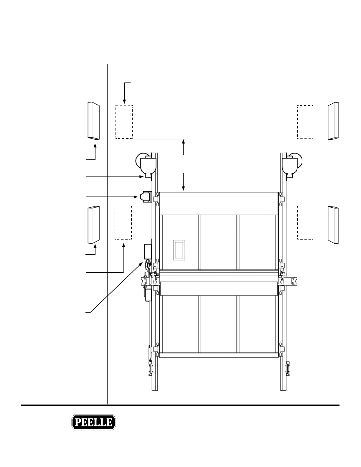
2.0 LANDING DOOR CONTROLLER INSTALLATION
2.1 LANDING DOOR CONTROLLER MOUNTING
Mount the Landing door Controller
to the hoistway wall.
Use 1/4” inch hardware.
Alternate Location
Lowest Landing
Recommended
location
Operator
Encoder
Floors above
lowest landing
Recommended
locations
Alternate Location
Interlock
4 Feet
[1 meter]
SLAVE
Controller
locations
(where
provided)
THE PEELLE COMPANY
FREIGHT DOORSICAR GATESICAR ENCLOSURES
2
Guide No.
VERSION:
WIRELESS CONTROLLER & BRIDGE
INSTALLATION & INTERFACE GUIDE
Date:
Mar 07 / 2018
254-EN
Page 7
TECHNICAL SUPPORT 1-800-787-5020 ext 275
®
2.2 LANDING DOOR WIRING LAYOUT - STANDARD OPERATORS (OPTION)
Power
Operator
Encoder
Operator
Landing
Door
Controller
HOISTWAY TROUGH
EUD
Interlock
Landing
Door
Junction
Box or
Tro u gh
Door lock contact (DI) and
Door Close Contact (DC)
connect to elevator controller
Hall Pushbuttons
THE PEELLE COMPANY
FREIGHT DOORSICAR GATESICAR ENCLOSURES
3
Guide No.
254-EN
VERSION:
WIRELESS CONTROLLER & BRIDGE
INSTALLATION & INTERFACE GUIDE
Date:
Mar 07 / 2018
Page 8
TECHNICAL SUPPORT 1-800-787-5020 ext 275
®
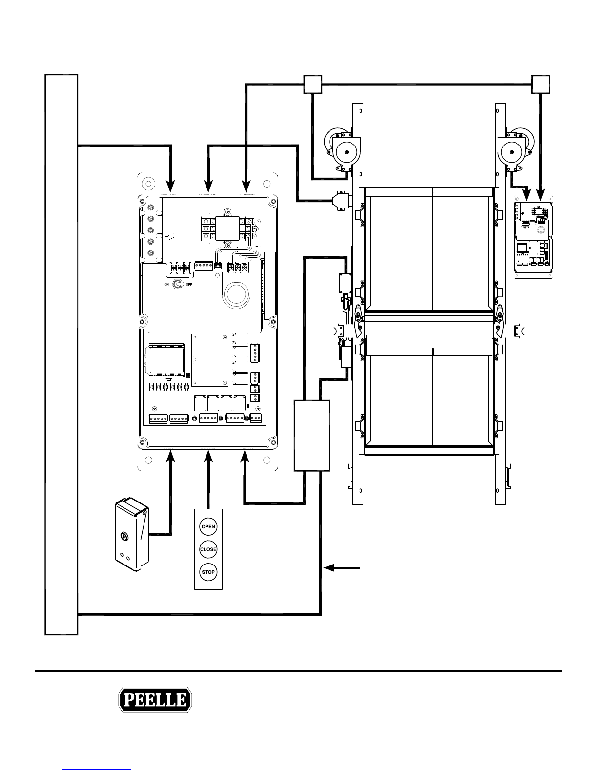
2.3 LANDING DOOR WIRING LAYOUT - EXTRA HIGH TORQUE OPERATORS
Power
Operator
Encoder
Landing
Door
Controller
Interlock
Operator
Slave
Controller
HOISTWAY TROUGH
EUD
Hall Pushbuttons
THE PEELLE COMPANY
FREIGHT DOORSICAR GATESICAR ENCLOSURES
Landing
Door
Junction
Box or
Tro u gh
4
Door lock contact (DI) and
Door Close Contact (DC)
connect to elevator controller
Guide No.
254-EN
VERSION:
WIRELESS CONTROLLER & BRIDGE
INSTALLATION & INTERFACE GUIDE
Date:
Mar 07 / 2018
Page 9
TECHNICAL SUPPORT 1-800-787-5020 ext 275
®
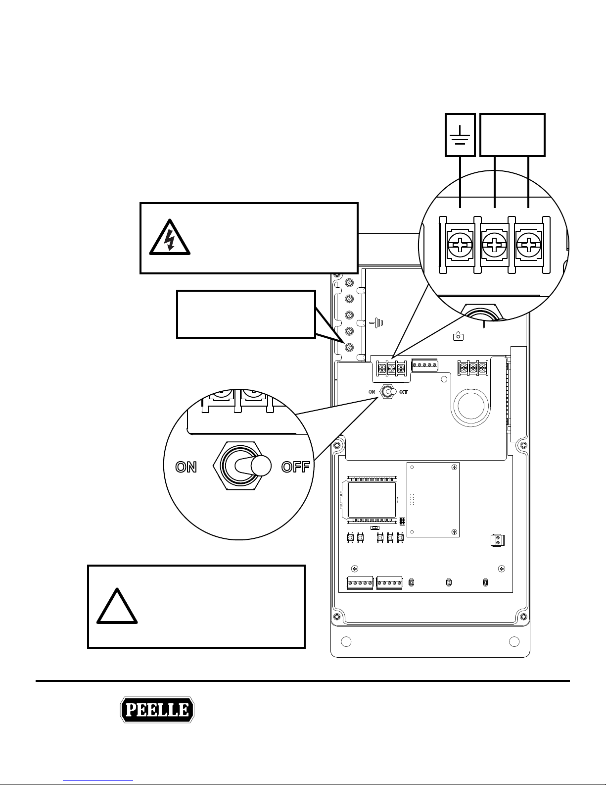
2.4 LANDING DOOR POWER CONNECTIONS
Connect controllers in accordance with local electrical codes.
Power branch circuit should come from machine room disconnect
10 amp circuit for each line of doors. Use #14AWG [2mm]
copper wire for power connection.
• ON/OFF switch disconnects both lines
• If neutral is not used, main disconnect must break both lines.
1 Ø Power
208-240V AC
5.5A, 50/60 Hz
WARNING
HIGH VOLTAGES
Read Safety Warning before
attempting to use this controller
CONDUIT AND SHIELD
GROUNDING LUG
GND L1 L2 / N
Landing
Door
Controller
The enclosure supplied is nonmetallic and does not provide
!
grounding between conduit
connections. Use grounding
bushings or jumper wires.
THE PEELLE COMPANY
FREIGHT DOORSICAR GATESICAR ENCLOSURES
Power
5
Guide No.
VERSION:
WIRELESS CONTROLLER & BRIDGE
INSTALLATION & INTERFACE GUIDE
Date:
Mar 07 / 2018
254-EN
Page 10
TECHNICAL SUPPORT 1-800-787-5020 ext 275
®
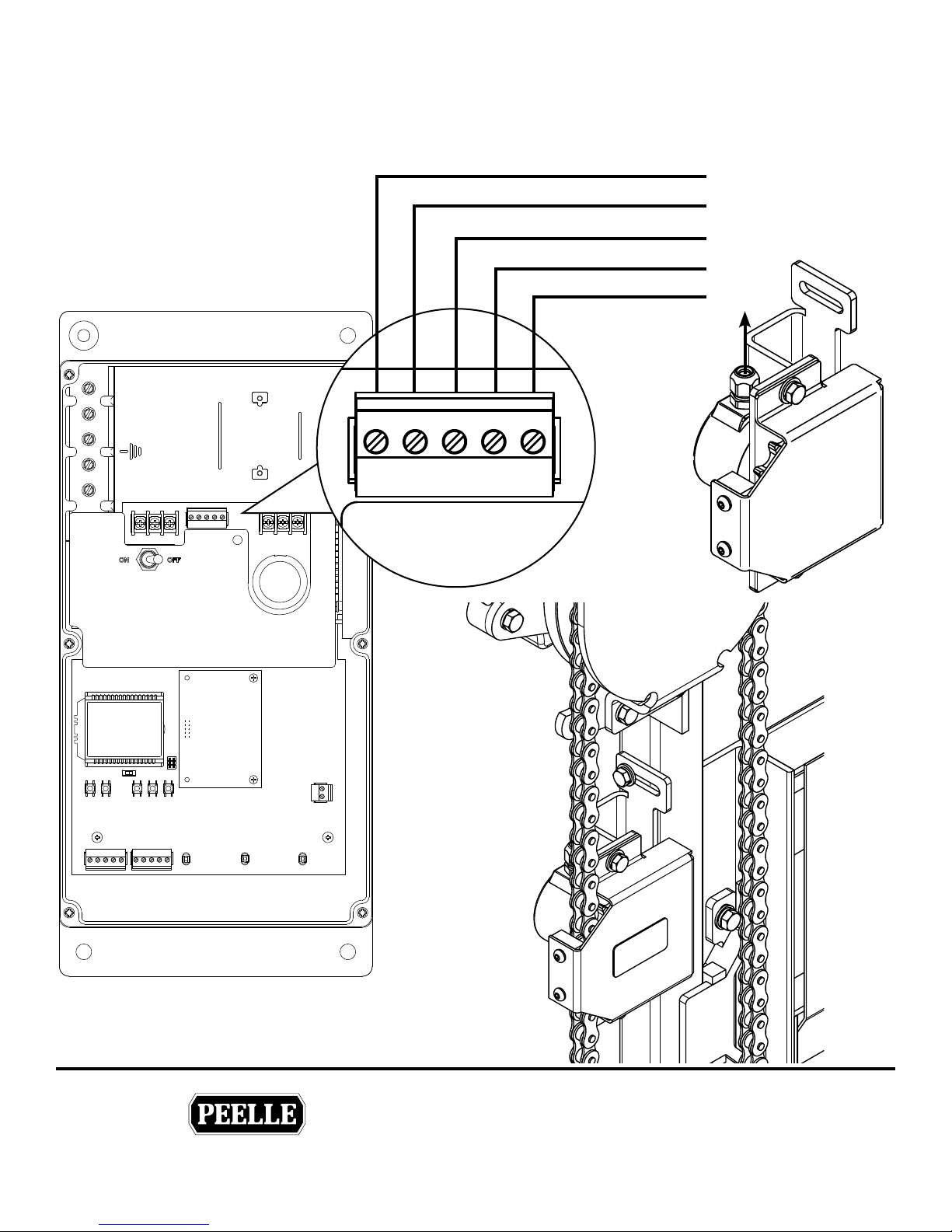
2.5 LANDING DOOR ENCODER
Install and wire encoder same side as the controller. Do not extend the encoder wire.
Shield
White
Yellow
Green
Brown
Landing
Door
Controller
GND COMM B
ENCODER
A 12V
Landing Door
Encoder
THE PEELLE COMPANY
FREIGHT DOORSICAR GATESICAR ENCLOSURES
Landing Door
Encoder
6
Guide No.
VERSION:
WIRELESS CONTROLLER & BRIDGE
INSTALLATION & INTERFACE GUIDE
Date:
Mar 07 / 2018
254-EN
Page 11
TECHNICAL SUPPORT 1-800-787-5020 ext 275
®
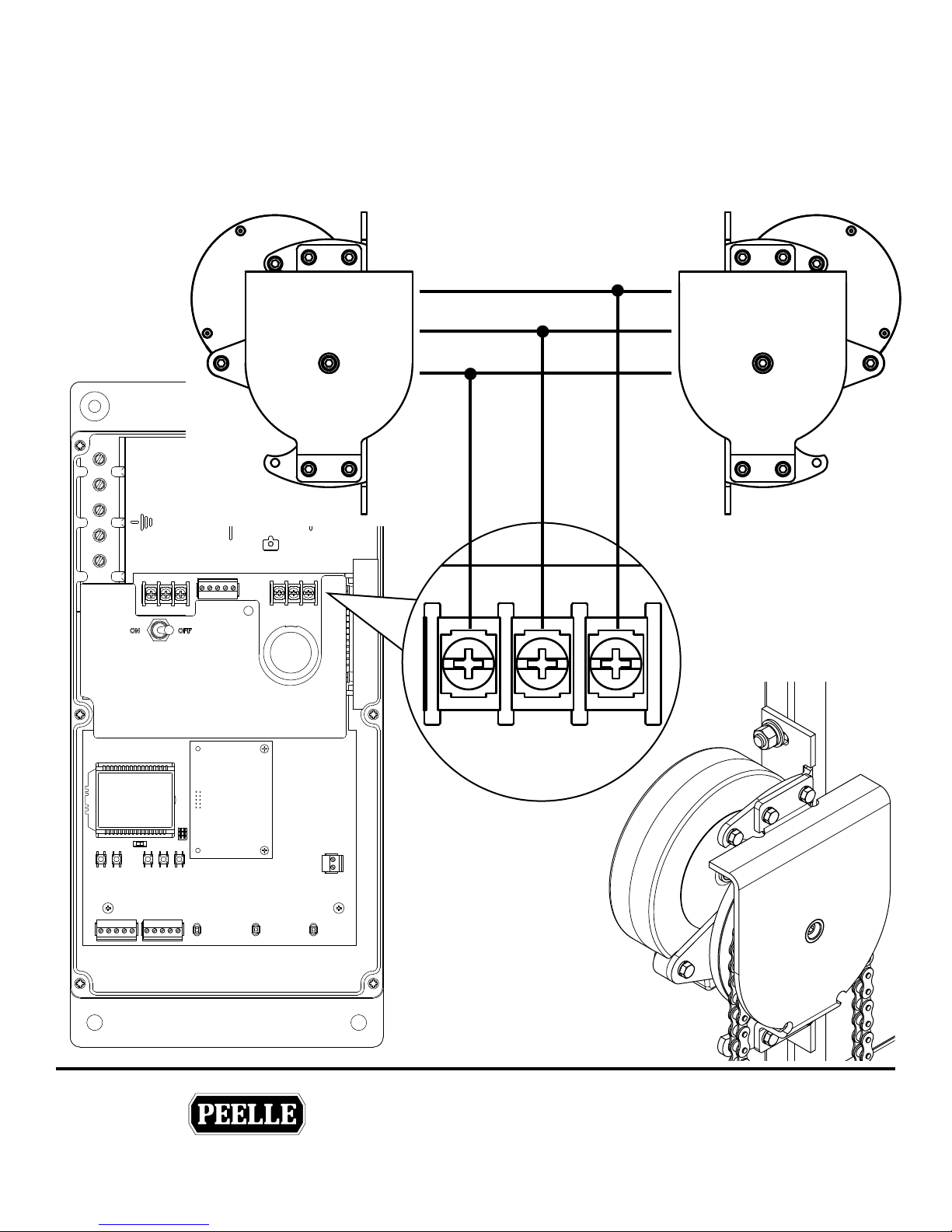
2.6 LANDING DOOR OPERATORS - STANDARD OPERATORS
Wire both door motors in parallel. Use #18AWG [1mm] wire in conduit for motor connection. Do not combine
motor wires with control wires in same conduit.
Note: Low speed winding is not used. Cap black wires separately (R4-R5).
Landing
Door
Controller
Landing Door
Operator
T1
R2
R3
3 2 1
T1
R2
R3
Landing Door
Operator
THE PEELLE COMPANY
FREIGHT DOORSICAR GATESICAR ENCLOSURES
7
MOTOR
Landing Door
Operator
Guide No.
VERSION:
WIRELESS CONTROLLER & BRIDGE
INSTALLATION & INTERFACE GUIDE
Date:
254-EN
Mar 07 / 2018
Page 12
TECHNICAL SUPPORT 1-800-787-5020 ext 275
®
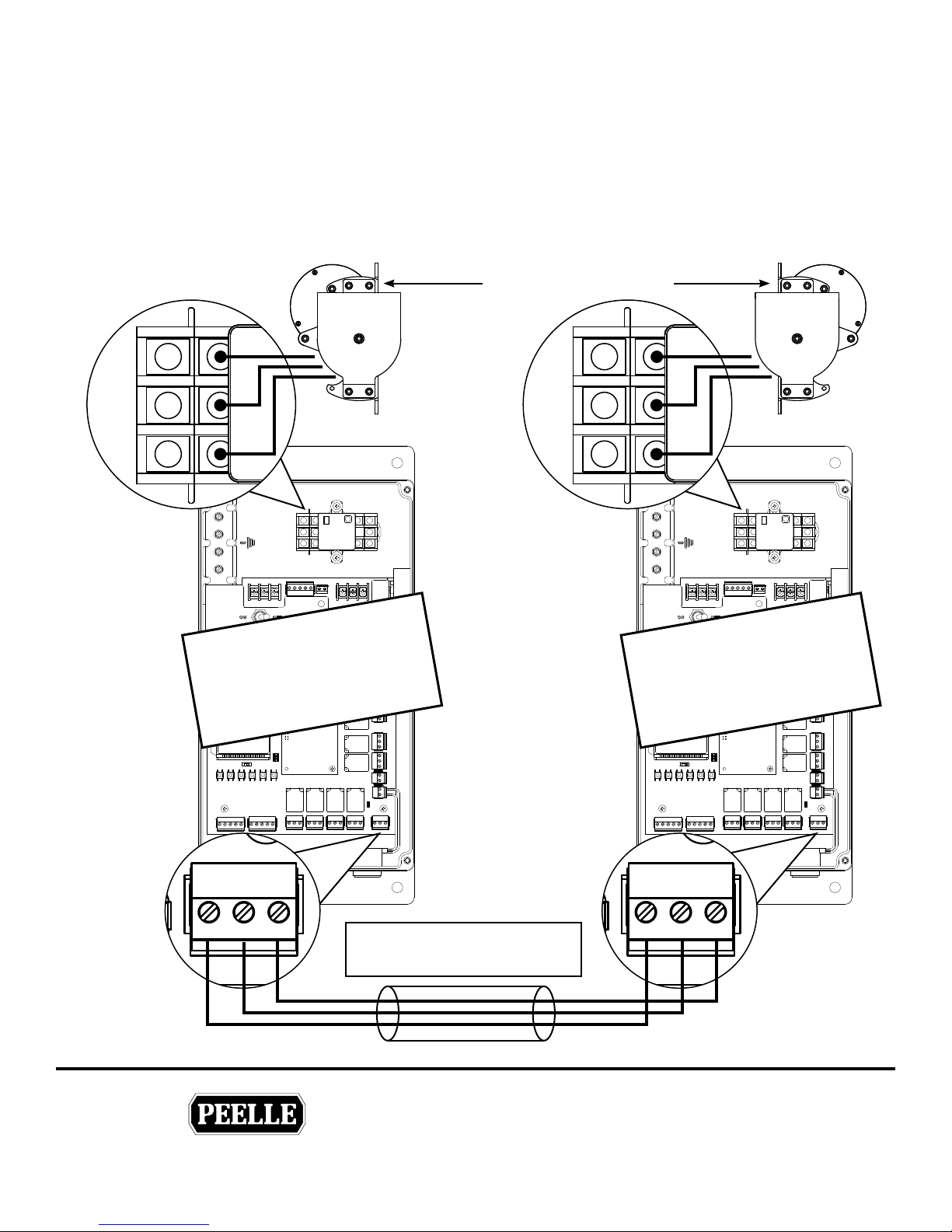
2.7 LANDING DOOR OPERATORS - EXTRA HIGH TORQUE (OPTION)
Use #18AWG [1mm] wire in conduit for motor connection. Do not combine motor wires with control wires in
same conduit. Connect CAN and COMM wires between controllers.
Notes
1. Low speed winding is not used. Cap black wires separately (R4-R5)
2. Use shielded wire or separate conduit for CAN bus connection slave
Extra High Torque
Landing Door Operator
T1
1
R2
2
R3
3
MASTER
CONTROLLER
T1
1
R2
2
R3
3
SLAVE
CONTROLLER
CANL CANH COMM CANL CANH COMM
THE PEELLE COMPANY
FREIGHT DOORSICAR GATESICAR ENCLOSURES
Attention!
Sheilded or separate conduit
8
Guide No.
VERSION:
WIRELESS CONTROLLER & BRIDGE
INSTALLATION & INTERFACE GUIDE
Date:
Mar 07 / 2018
254-EN
Page 13
TECHNICAL SUPPORT 1-800-787-5020 ext 275
®
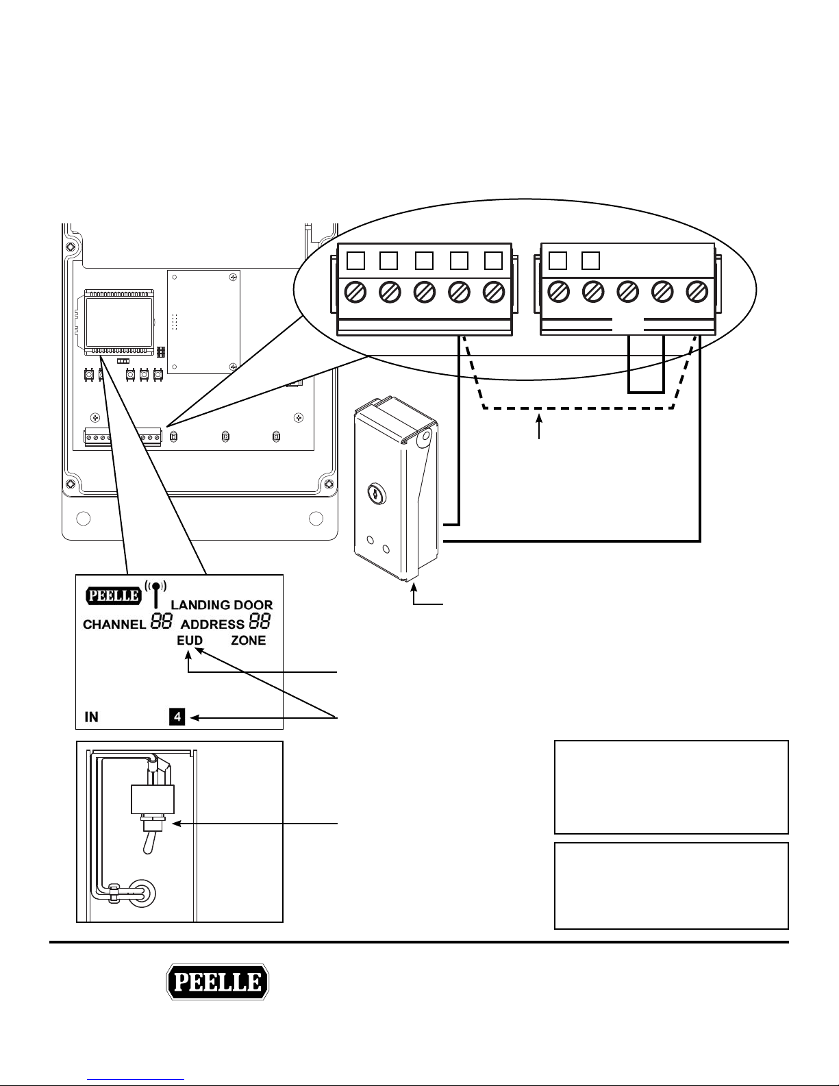
2.8 LANDING DOOR EMERGENCY UNLOCKING DEVICE (EUD)
The Emergency Unlocking Device is located on the landing side and contains a toggle switch which must be wired
to the controller.
NOTE: Only in jurisdictions not requiring unlocking devices, a jumper needs to but added in lieu of the EUD
switch.
Landing Door
Controller
1 2 3 4 5 6 7
RESET SET
HDO HDC ZNS EUD
e EUD indicator will ash ON all controllers in that channel to
indicate there is a SET EUD at another oor.
e EUD and input indicator 4 will go ON solid when the EUD
switch is in the SET position (activated) for the door connected to
that controller.
For automatic door operation,
ALL the EUD switches have to
be in the RESET position as
shown.
(RESET is normally closed)
STOP
Add jumper where EUD’s
are not provided
Emergency Unlocking Device
AUX1
AUX2
INPUT
COM
Attention!
Three quick buzzer outputs (from
car controller) indicates the EUD
is set on that channel
Attention!
When EUD is SET (at any oor)
Doors on the same channel will
not run.
V- V+
THE PEELLE COMPANY
FREIGHT DOORSICAR GATESICAR ENCLOSURES
9
Guide No.
VERSION:
WIRELESS CONTROLLER & BRIDGE
INSTALLATION & INTERFACE GUIDE
Date:
Mar 07 / 2018
254-EN
Page 14
TECHNICAL SUPPORT 1-800-787-5020 ext 275
®
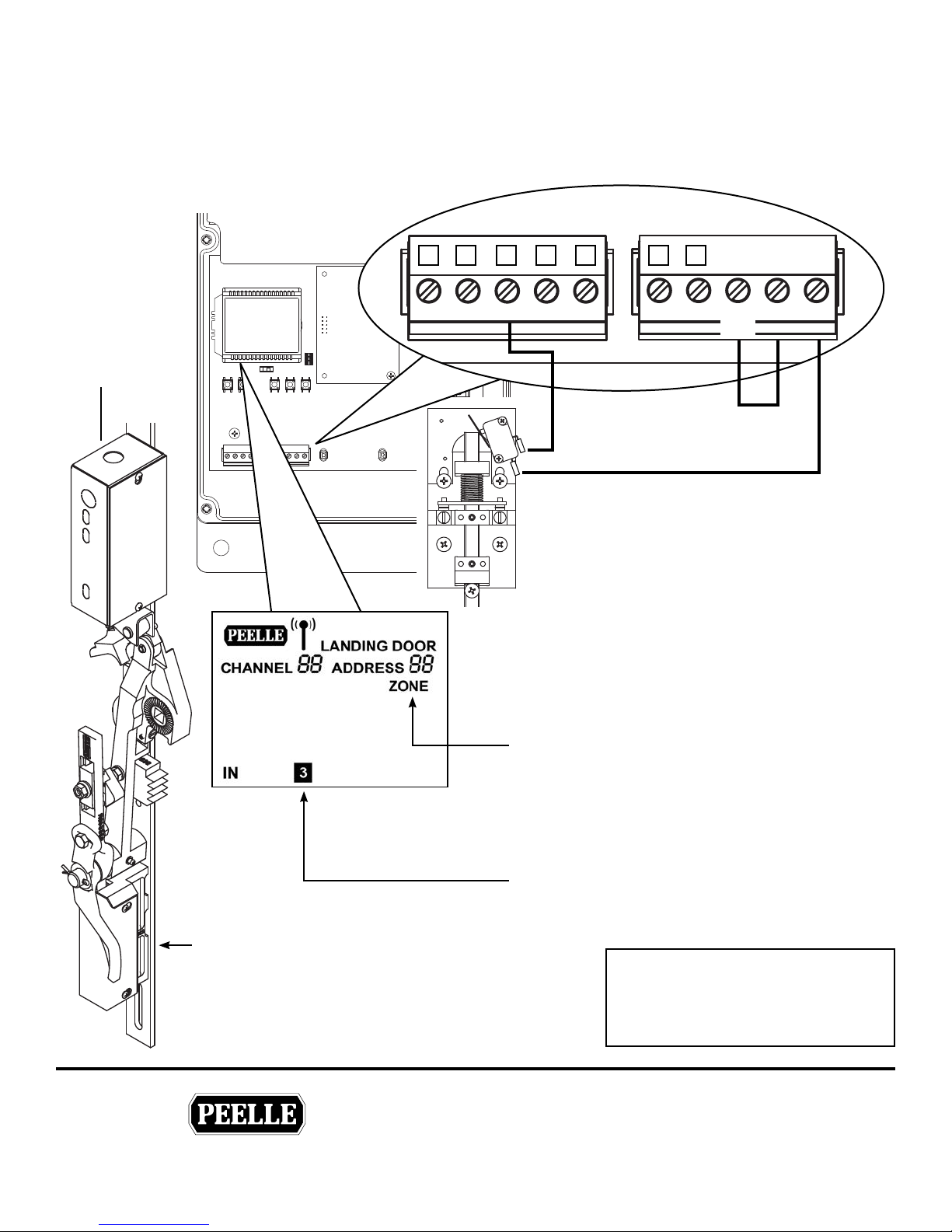
2.9 LANDING DOOR ZONE SWITCH (ZNS)
The landing door Zone Switch located in top of interlock box activates the controller for the Landing door at
which the elevator car is located.
Landing Door
Controller
1 2 3 4 5 6 7
Interlock
DI contact
and ZNS
HDOHDC ZNS EUD
Door Lock Contact (DI)
connect to elevator controller
e ZONE indicator will go ON solid when the
ZNS contact is made for the door connected to
that controller when elevator is at the landing with
retiring cam extended
ZONE turns OFF when the retiring cam lis.
STOP
AUX1
AUX2
INPUT
COM
V- V+
Interlock DC contact
THE PEELLE COMPANY
FREIGHT DOORSICAR GATESICAR ENCLOSURES
10
When the retiring cam lis the ZNS contact is
open and the ZONE indicator turns o.
e input indicator 3 will go ON solid when the
ZNS contact is made for the door connected to
that controller.
Attention!
The ZONE must be made for
automatic door operation. If ZONE
is not made doors will not run.
Guide No.
VERSION:
WIRELESS CONTROLLER & BRIDGE
INSTALLATION & INTERFACE GUIDE
Date:
Mar 07 / 2018
254-EN
Page 15
TECHNICAL SUPPORT 1-800-787-5020 ext 275
®
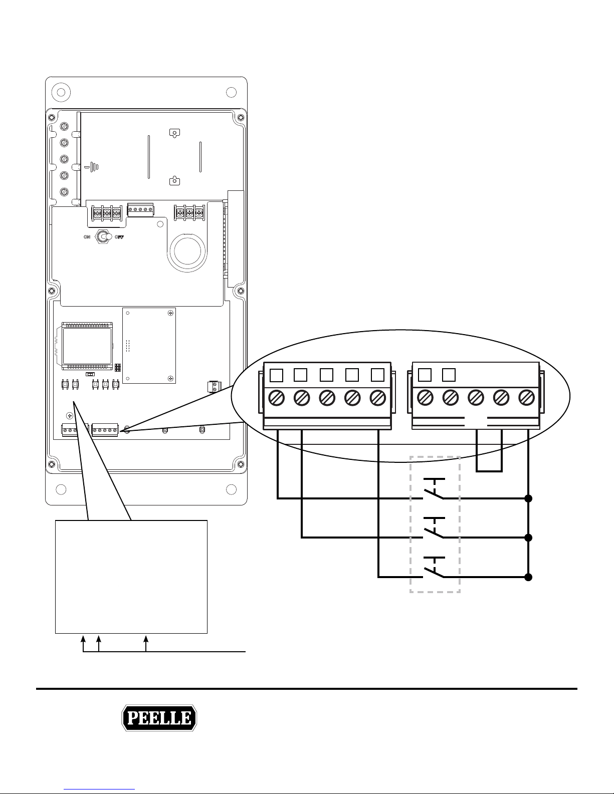
2.10 LANDING DOOR HALL PUSHBUTTONS
Landing
Door
Controller
HALL DOOR OPEN BUTTON (HDO)
Where provided, wire landing station door OPEN pushbuttons
as shown. When elevator car is within landing ZONE,
pushbutton inputs will be transmitted to the Car Door controller
for connection to elevator control.
HALL DOOR CLOSE BUTTON (HDC)
Where provided, wire landing station door CLOSE pushbutton
as shown. When elevator car is within oor ZONE, pushbutton
inputs will be transmitted to the Car Door controller for
connection to elevator control.
DOOR STOP BUTTON (STOP) 5
Where provided, wire landing station door STOP pushbutton as
shown. The door STOP button should be normally open (NO). If
normally closed (NC) set parameter 96 to 01. See DOOR STOP
output for connection to elevator control.
1
2
2 3 4 5 6 7
1
HDCHDO ZNS EUD
e input indicators 1 2 and 5 will go ON when the
pushbutton is activated for the door connected to that controller.
STOP
Landing Station
AUX1
OPEN
CLOSE
STOP
AUX2
INPUT
COM
V- V+
THE PEELLE COMPANY
FREIGHT DOORSICAR GATESICAR ENCLOSURES
11
Guide No.
VERSION:
WIRELESS CONTROLLER & BRIDGE
INSTALLATION & INTERFACE GUIDE
Date:
Mar 07 / 2018
254-EN
Page 16
TECHNICAL SUPPORT 1-800-787-5020 ext 275
®
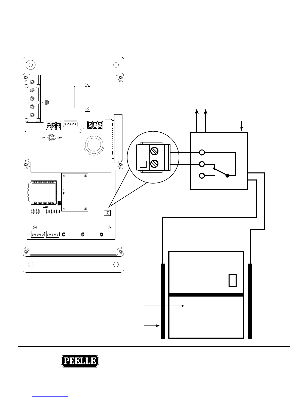
2.11 LANDING DOOR LIGHT CURTAIN (OPTIONAL)
Install and wire Landing Door Light Curtain where provided.
Note: V+ to RE contact must close when beams are blocked
To landing box
or trough
Light Curtain
Controller
Power
Landing
Door
Controller
8
V+
RE
Use N.C. contact
See job specic
wiring schematic
THE PEELLE COMPANY
FREIGHT DOORSICAR GATESICAR ENCLOSURES
Landing Door
Landing Door
Light Curtain
12
Guide No.
VERSION:
WIRELESS CONTROLLER & BRIDGE
INSTALLATION & INTERFACE GUIDE
Date:
Mar 07 / 2018
254-EN
Page 17
TECHNICAL SUPPORT 1-800-787-5020 ext 275
®
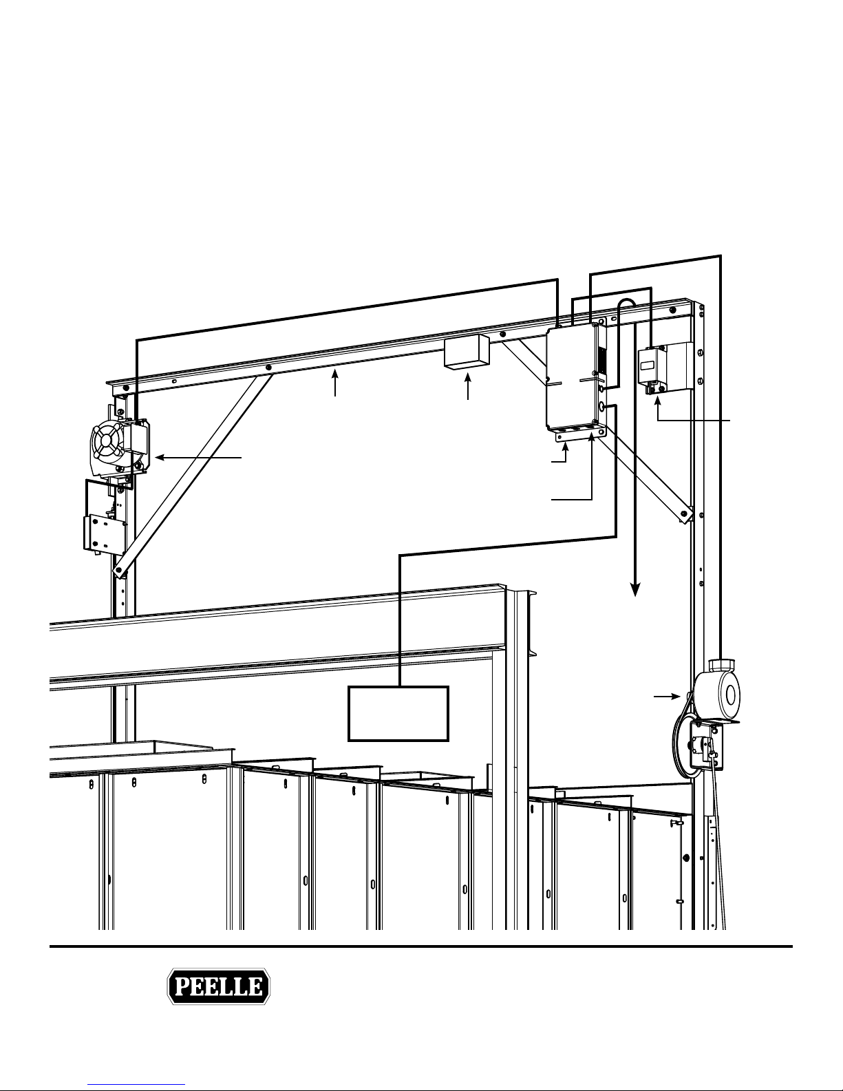
3.0 CAR DOOR (GATE) CONTROLLER INSTALLATION
3.1 CAR DOOR LOCATION AND WIRING LAYOUT
Mount the Car Door Controller to the car door rail spreader. Mount to same side as the Encoder. Use 1/4”
Hardware.
Car Door
Motor
Spreader
Light Curtain
Car Door Controller
Ca r Top
Junction Box
Controller
Car Door Buzzer
Encoder
Reversing
Edge
Retiring Cam
Motor
THE PEELLE COMPANY
FREIGHT DOORSICAR GATESICAR ENCLOSURES
13
Guide No.
VERSION:
WIRELESS CONTROLLER & BRIDGE
INSTALLATION & INTERFACE GUIDE
Date:
Mar 07 / 2018
254-EN
Page 18
TECHNICAL SUPPORT 1-800-787-5020 ext 275
®
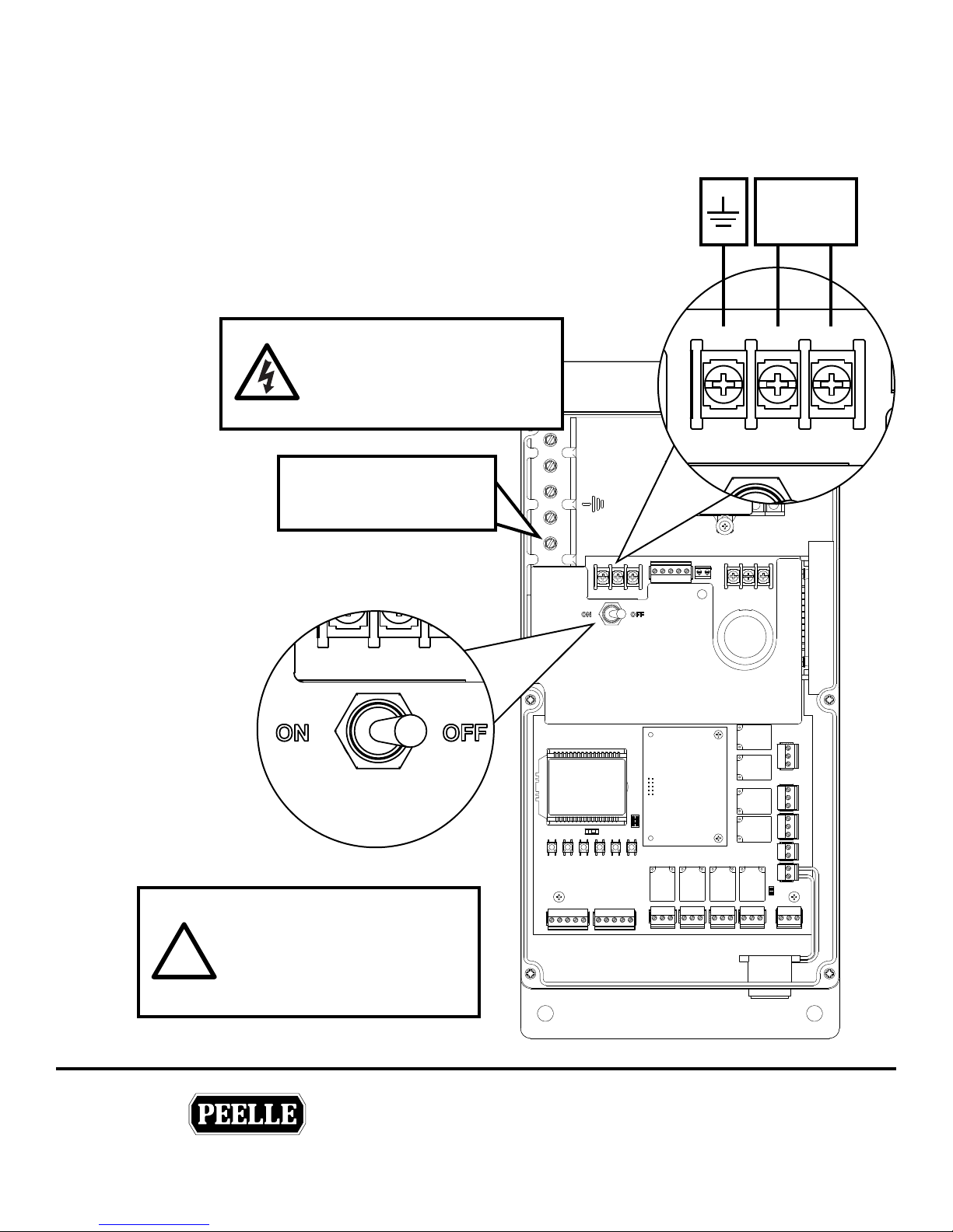
3.2 CAR DOOR POWER CONNECTIONS
Connect controllers in accordance with local electrical codes.
Power branch circuit should come from machine room disconnect
10 amp circuit for each line of doors. Use #14AWG [2mm]
copper wire for power connection.
• ON/OFF switch disconnects both lines
• If neutral is not used, main disconnect must break both lines.
1 Ø Power
208-240V AC
5.5A, 50/60 Hz
WARNING
HIGH VOLTAGES
Read Safety Warning before
attempting to use this controller
CONDUIT AND SHIELD
GROUNDING LUG
GND L1 L2 / N
Car Door
Controller
The enclosure supplied is nonmetallic and does not provide
!
grounding between conduit
connections. Use grounding
bushings or jumper wires.
THE PEELLE COMPANY
FREIGHT DOORSICAR GATESICAR ENCLOSURES
Power
14
Guide No.
VERSION:
WIRELESS CONTROLLER & BRIDGE
INSTALLATION & INTERFACE GUIDE
Date:
Mar 07 / 2018
254-EN
Page 19
TECHNICAL SUPPORT 1-800-787-5020 ext 275
®
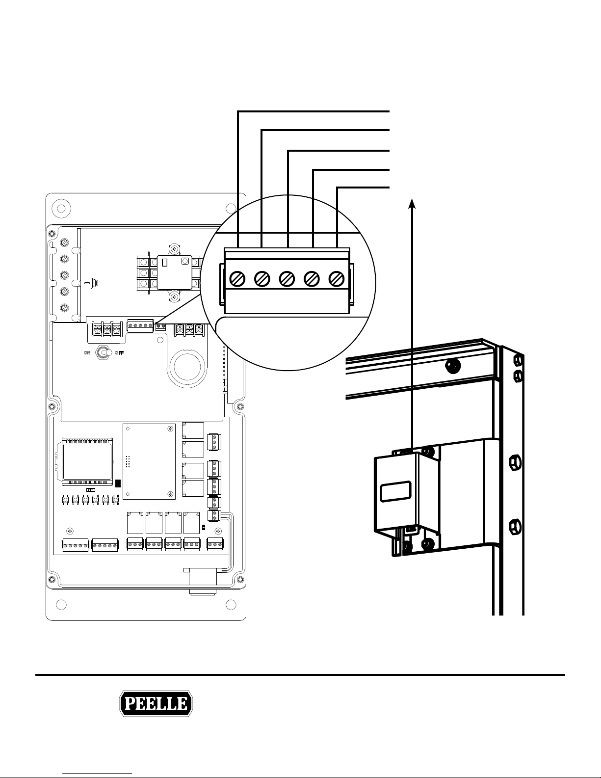
3.3 CAR DOOR ENCODER
Install and wire encoder. Do not extend the encoder wire.
Shield
White
Yellow
Green
Brown
Car Door
Controller
GND COMM B
ENCODER
A 12V
Car Door
Encoder
THE PEELLE COMPANY
FREIGHT DOORSICAR GATESICAR ENCLOSURES
15
Guide No.
VERSION:
WIRELESS CONTROLLER & BRIDGE
INSTALLATION & INTERFACE GUIDE
Date:
Mar 07 / 2018
254-EN
Page 20
TECHNICAL SUPPORT 1-800-787-5020 ext 275
®
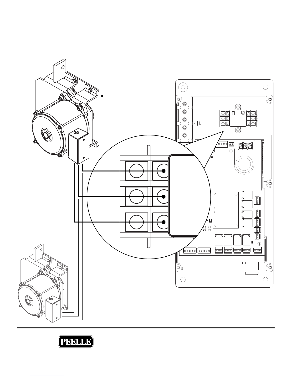
3.4 CAR DOOR (GATE) OPERATOR
Use #18AWG [1mm] wire in conduit for motor connection.
Do not combine motor wires with control wires in same conduit.
Note: Low speed winding is not used. Cap black wires separately (T8-T9).
Car Door
Operator
T1
T6
T7
On large car doors
where provided wire
opposite car door
operator in parallel.
1
Car Door
Controller
2
3
THE PEELLE COMPANY
FREIGHT DOORSICAR GATESICAR ENCLOSURES
16
Guide No.
VERSION:
WIRELESS CONTROLLER & BRIDGE
INSTALLATION & INTERFACE GUIDE
Date:
Mar 07 / 2018
254-EN
Page 21
TECHNICAL SUPPORT 1-800-787-5020 ext 275
®
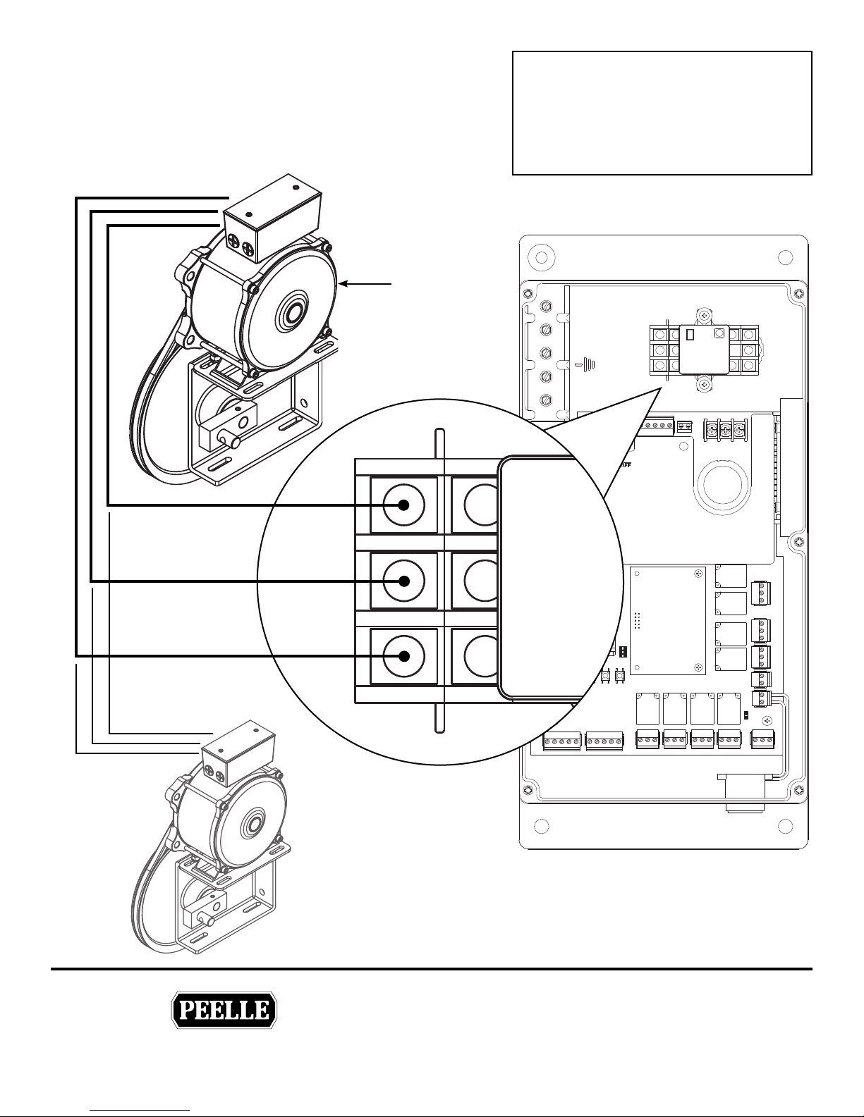
3.5 RETIRING CAM MOTOR
Use #18AWG [lmm] wire in conduit for motor connection.
Do not combine motor wires with control wires in same conduit.
Retiring Cam
Motor
Attention!
220 Volt 3 Ø Retiring Cam Motors Only
For 110 Volt 1 Ø Retiring Cam Motors for
battery lowering see elevator control panel
Y1
Y2
Y3
4
5
6
Where provided on
wide landing doors,
wire opposite side
retiring cam motor in
parallel.
Car Door
Controller
THE PEELLE COMPANY
FREIGHT DOORSICAR GATESICAR ENCLOSURES
17
Guide No.
VERSION:
WIRELESS CONTROLLER & BRIDGE
INSTALLATION & INTERFACE GUIDE
Date:
Mar 07 / 2018
254-EN
Page 22
TECHNICAL SUPPORT 1-800-787-5020 ext 275
®
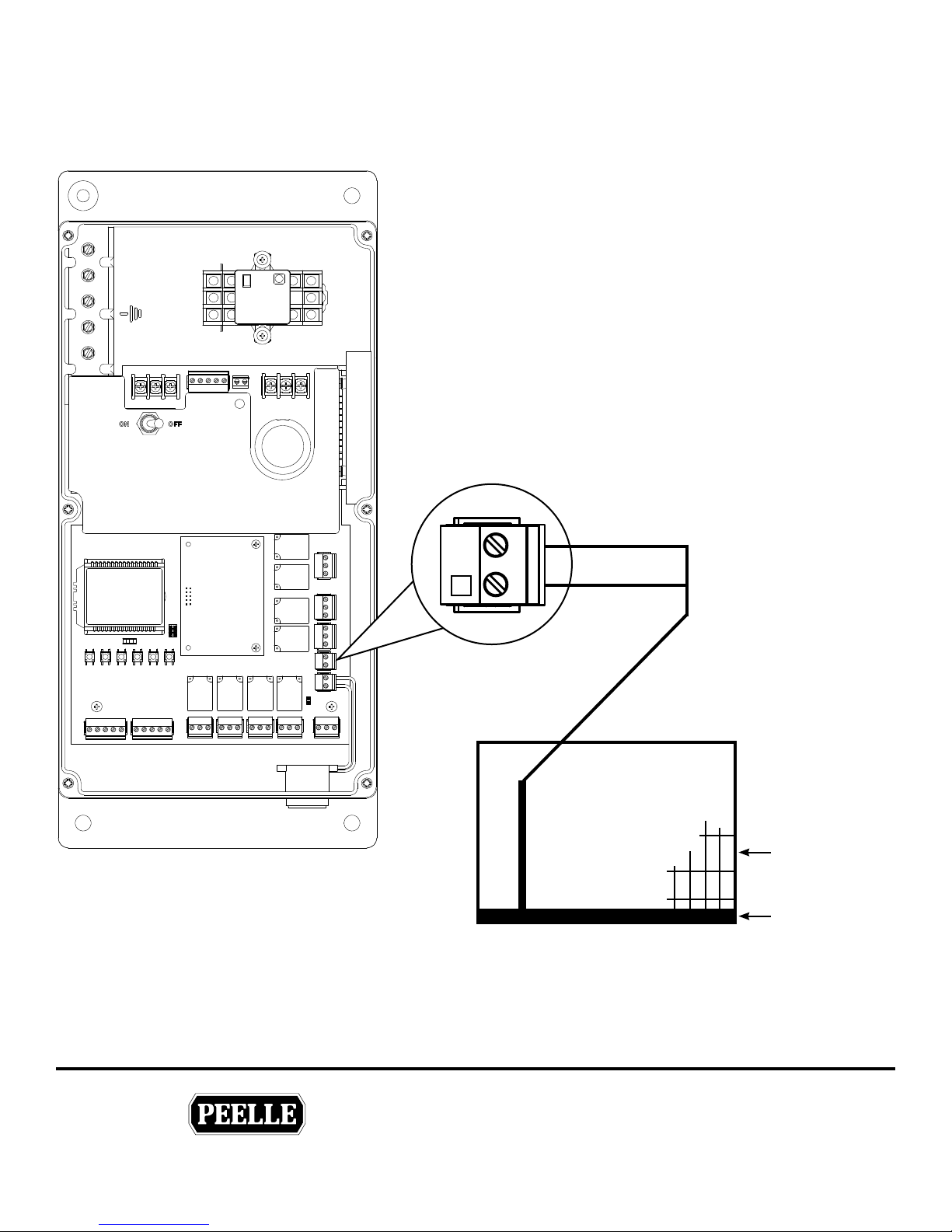
3.6 CAR DOOR REVERSING EDGE (OPTIONAL)
Wire reversing edge as shown where provided.
Note V+ to RE contact closes when reversing edge is obstructed.
L
Car Door
Controller
See job specic
wiring schematic
V+
8
RE
Car Door Panel
Reversing Edge
THE PEELLE COMPANY
FREIGHT DOORSICAR GATESICAR ENCLOSURES
18
Guide No.
VERSION:
WIRELESS CONTROLLER & BRIDGE
INSTALLATION & INTERFACE GUIDE
Date:
Mar 07 / 2018
254-EN
Page 23
TECHNICAL SUPPORT 1-800-787-5020 ext 275
®
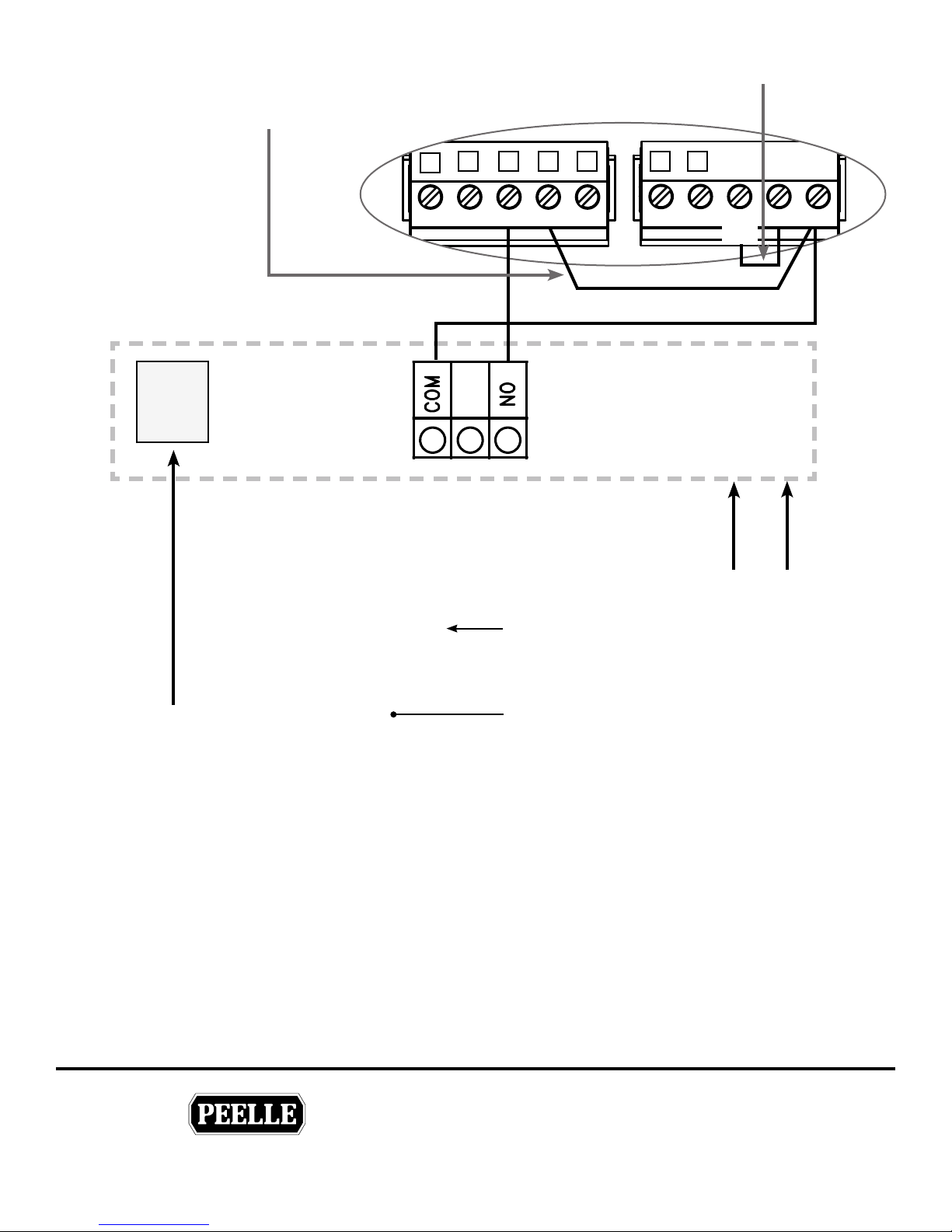
3.7 SINGLE LIGHT CURTAIN (OPTION)
For Single Light Curtain option, you must
L
add a jumper from V+ to DCM
2 3 4 5 6 7
1
Add Jumper
LC#1
PLUG
See job specic
wiring schematic
DCD0 SE DCM
Light Curtain #1
RC
AUX2
BUZZ
INPUT
Light Curtain
Power Supply
Power In
L1 N
100-240 VAC
V- V+
COM
Inside the Car
THE PEELLE COMPANY
FREIGHT DOORSICAR GATESICAR ENCLOSURES
Car Door Panel
LIGHT CURTAIN #1 (SE) 3
Wire light curtain RD1 output as shown use normally
open (NO) signal from light curtain controller.
Wire V+ to Input 4.
19
Guide No.
VERSION:
WIRELESS CONTROLLER & BRIDGE
INSTALLATION & INTERFACE GUIDE
254-EN
Date:
Mar 07 / 2018
Page 24
TECHNICAL SUPPORT 1-800-787-5020 ext 275
®
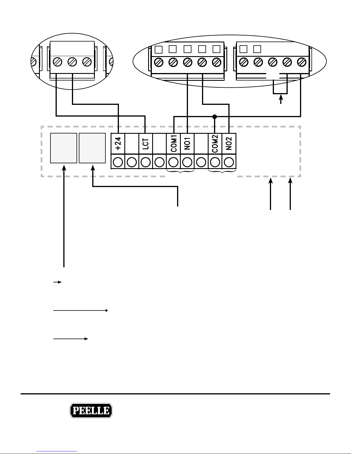
3.8 DUAL LIGHT CURTAINS (OPTION)
USER 1
NO COM6 NC
LC#1
PLUG
LC#2
PLUG
See job specic
wiring schematic
2 3 4 5 6 7
1
DCD0 SE DCM
RC
RD1 RD2
AUX2
BUZZ
INPUT
Add Jumper
Light Curtain
Power Supply
Power In
L1 N
V- V+
COM
Light
Curtain #1
Car Door
Panel
Light
Curtain #2
Inside the Car
100-240 VAC
LIGHT CURTAIN #1 (SE)
Wire light curtain RD1 output as shown use
normally open (NO) signal from light curtain
controller
LIGHT CURTAIN #2 (DCM)
Wire light curtain RD2 output as shown. Use
normally open (NO) signal from light curtain
controller.
LIGHT CURTAIN TEST OUTPUT (USER 1)
Wire light curtain test as shown for dual light
curtains. Use normally open (NO) from USER 1
relay output.
You must set parameter 65 to 07.
3
4
L
THE PEELLE COMPANY
FREIGHT DOORSICAR GATESICAR ENCLOSURES
20
Guide No.
VERSION:
WIRELESS CONTROLLER & BRIDGE
INSTALLATION & INTERFACE GUIDE
Date:
Mar 07 / 2018
254-EN
Page 25
TECHNICAL SUPPORT 1-800-787-5020 ext 275
®
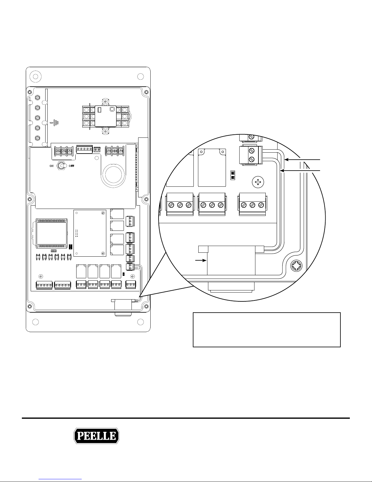
3.9 WARNING BUZZER
Install and wire door close warning buzzer as shown. See parameter 94 for constant or pulsing tone.
+
-
BUZZER
Car Door
Controller
RED
BLACK
THE PEELLE COMPANY
FREIGHT DOORSICAR GATESICAR ENCLOSURES
BUZZER
21
Attention!
Warning Buzzer is mounted in Auxiliary strobe
controller (27465) if strobe light is provided
Guide No.
VERSION:
WIRELESS CONTROLLER & BRIDGE
INSTALLATION & INTERFACE GUIDE
254-EN
Date:
Mar 07 / 2018
Page 26
TECHNICAL SUPPORT 1-800-787-5020 ext 275
®
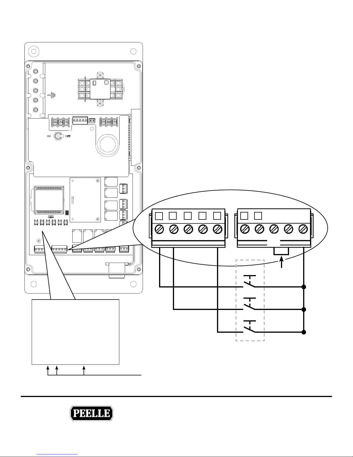
3.10 CAR STATION DOOR PUSHBUTTONS
Car Door
Controller
CAR DOOR OPEN BUTTON (DO)
Wire car station door OPEN pushbutton as shown.
CAR DOOR CLOSE BUTTON (DC) 2
Wire car station door CLOSE pushbutton as shown.
CAR DOOR STOP BUTTON (RC) 5
Where provided, wire car station door STOP pushbutton as
shown. The car door STOP button should be normally open
(NO). If normally closed (NC) set parameter 96 to 01. See
DOOR STOP output on bridge controller for connection to
elevator control.
1
2 3 4 5 6 7
1
DCDO SE DCM
e input indicators 1 2 or 5 will go ON when the
pushbutton is activated.
RC
AUX2
BUZZ
OPEN
CLOSE
STOP
Car Station
INPUT
COM
V- V+
Add
Jumper
THE PEELLE COMPANY
FREIGHT DOORSICAR GATESICAR ENCLOSURES
22
Guide No.
VERSION:
WIRELESS CONTROLLER & BRIDGE
INSTALLATION & INTERFACE GUIDE
Date:
Mar 07 / 2018
254-EN
Page 27

TECHNICAL SUPPORT 1-800-787-5020 ext 275
®
4.0 BRIDGE CONTROLLER INSTALLATION
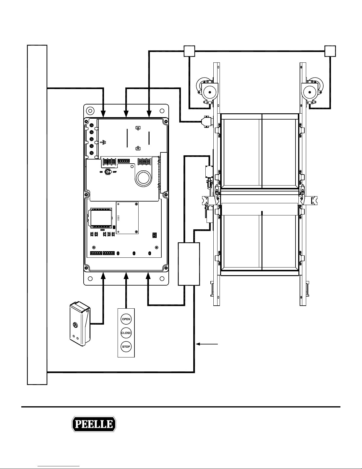
4.1 BRIDGE CONTROLLER LOCATION AND WIRING LAYOUT
MACHINE ROOM
Main
Disconnect
Peelle
Transformer
Peelle
Disconnect
Peelle Bridge
Controller
Elevator
Controller
THE PEELLE COMPANY
FREIGHT DOORSICAR GATESICAR ENCLOSURES
23
Guide No.
VERSION:
WIRELESS CONTROLLER & BRIDGE
INSTALLATION & INTERFACE GUIDE
Date:
Mar 07 / 2018
254-EN
Page 28
TECHNICAL SUPPORT 1-800-787-5020 ext 275
®
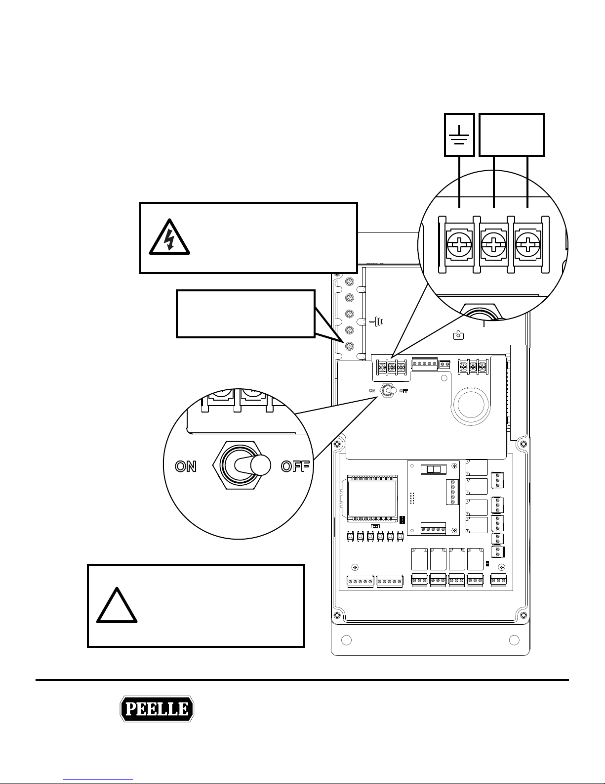
4.2 BRIDGE POWER CONNECTIONS
Connect controllers in accordance with local electrical codes.
Power branch circuit should come from machine room disconnect
10 amp circuit for each line of doors. Use #14AWG [2mm]
copper wire for power connection.
• ON/OFF switch disconnects both lines
• If neutral is not used, main disconnect must break both lines.
1 Ø Power
208-240V AC
5.5A, 50/60 Hz
WARNING
HIGH VOLTAGES
Read Safety Warning before
attempting to use this controller
CONDUIT AND SHIELD
GROUNDING LUG
GND L1 L2 / N
Bridge
Controller
The enclosure supplied is nonmetallic and does not provide
!
grounding between conduit
connections. Use grounding
bushings or jumper wires.
THE PEELLE COMPANY
FREIGHT DOORSICAR GATESICAR ENCLOSURES
Power
24
Guide No.
VERSION:
WIRELESS CONTROLLER & BRIDGE
INSTALLATION & INTERFACE GUIDE
Date:
Mar 07 / 2018
254-EN
Page 29
TECHNICAL SUPPORT 1-800-787-5020 ext 275
®
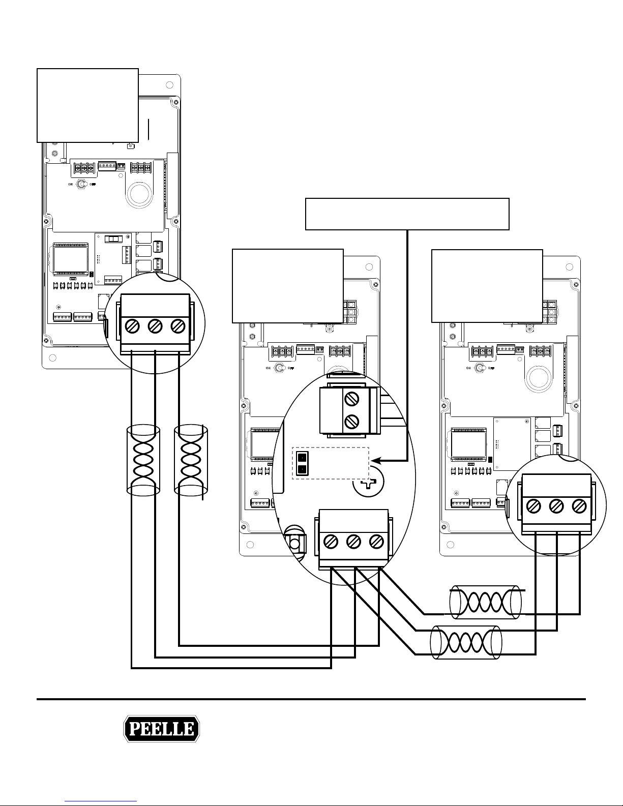
4.3 BRIDGE TO CAR DOOR CONNECTION
CAN BUS WIRING
BRIDGE
CONTROLLER
Wire Bridge Controller to the Car Door Controller in series as shown. Use
(2) shielded twisted pair in travel cable.
Located in
Machine Room
CANL CANH COMM
TERMINATING JUMPERS
For elevators with front doors only, do NOT remove terminating jumper.
For front & rear doors remove terminating jumper on Front Car Door
Controller only.
Terminating Jumper located between
CAN and BUZZER connectors
CAR DOOR
CONTROLLER
LINE A (FRONT)
Located on Car Top
CAR DOOR
CONTROLLER
LINE C (REAR)
Located on Car Top
BUZZER
TERMINATING
JUMPER
CANL CANH COMM
CANL CANH COMM
THE PEELLE COMPANY
FREIGHT DOORSICAR GATESICAR ENCLOSURES
25
Guide No.
VERSION:
WIRELESS CONTROLLER & BRIDGE
INSTALLATION & INTERFACE GUIDE
Date:
Mar 07 / 2018
254-EN
Page 30
TECHNICAL SUPPORT 1-800-787-5020 ext 275
®
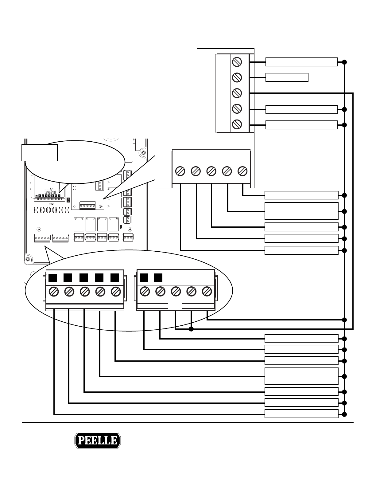
4.4 ELEVATOR TO BRIDGE CONTROLLER INPUT CONNECTIONS
CONTROLLER INTERFACE
Inputs to the Bridge controller are the only interface to
the elevator control for door operation. A single Bridge
Controller is used for front doors or for front and rear door
arrangement.
INPUT COM
Add jumper to the INPUT COM from V- when car door
controller V+ is used for the input voltage.
Where elevator control voltage is used, connect
L
INPUT COM to elevator controller according to
elevator control prints. Do not use V+ or V-.
LCD INPUT
INDICATORS
1
8
7
6
2 3 4 5
DCRDOR INSR DCMR
X13
N/C
X14 X18 COM HDB
ELEVATOR
CONTROLLER
HALL DOOR BUTTON DISABLE
NO CONNECTION
PHASE 2 “OFF”
PHASE 2 “HOLD”
PHASE 2 “ON”
REAR DOOR CLOSE
MOMENTARY
2 3 4 5 6 7
1
DCD0 INS DCM
RC
X11
X12
INPUT
COM
REAR INSPECTION
REAR DOOR CLOSE
REAR DOOR OPEN
V- V+
DESIGNATED LANDING
PHASE 1 RECALL
RETIRING CAM
FRONT DOOR CLOSE
MOMENTARY
FRONT INSPECTION
FRONT DOOR CLOSE
THE PEELLE COMPANY
FREIGHT DOORSICAR GATESICAR ENCLOSURES
26
FRONT DOOR OPEN
Guide No.
254-EN
VERSION:
WIRELESS CONTROLLER & BRIDGE
INSTALLATION & INTERFACE GUIDE
Date:
Mar 07 / 2018
Page 31

TECHNICAL SUPPORT 1-800-787-5020 ext 275
®
ELEVATOR TO BRIDGE CONTROLLER INPUT CONNECTIONS CONTINUED
DO - Front Door Open
1
Momentary front signal required to open doors
DC - Front Door Close
2
Constant signal required to close doors
SE - Front Inspection
3
Constant signal required for front door operation
DCM - Front Door Close Momentary
4
Momentary signal required to initiate Auto Close sequence
RC - Retiring Cam
5
Input required to lift cam and move car. Signal should be low whenever car is stopped.
X11 - Fire Service Phase 1 Recall
6
Input required when Fire Service Phase 1 Recall is on.
X12 - Designated Landing Door
7
Input required when elevator is at designated landing
DOR - Rear Door Open
1
Momentary signal to open doors
DCR - Rear Door Close
2
Constant Signal required to close doors
INSR - Rear Inspection
3
Constant signal required for rear door operation
DCMR - Rear Door Close Momentary
4
Momentary signal required to initiate Auto Close sequence
X13 - Phase 2 “ON”
5
Constant signal required in phase 2 operation
X14 - Phase 2 “HOLD”
6
Constant signal required in phase 2 “HOLD” operation
X18 - Phase 2 “OFF”
7
Constant signal required in phase 2 “OFF” operation (until recall)
HDB - Hall Door Button Disable
8
Constant signal required to enable hall buttons
THE PEELLE COMPANY
FREIGHT DOORSICAR GATESICAR ENCLOSURES
27
Guide No.
VERSION:
WIRELESS CONTROLLER & BRIDGE
INSTALLATION & INTERFACE GUIDE
Date:
Mar 07 / 2018
254-EN
Page 32
TECHNICAL SUPPORT 1-800-787-5020 ext 275
®
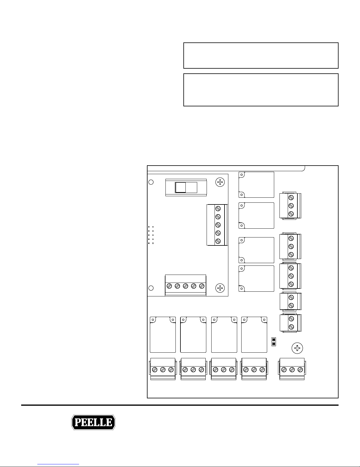
4.5 BRIDGE CONTROLLER TO ELEVATOR OUTPUT CONNECTIONS
Hall Stop Buttons
DSF - Front Door Stop - Relay COM1
Contact closes when door stops during operation
Attention!
See Parameter 97 for power-up mode relay condition.
sequence
DSR - Rear Door Stop - Relay COM1
Contact closes when door stops during operation
sequence
Elevator controller interface connections to
L
the Bridge Controller ONLY. No connection to
landing door controller, or car door controller.
Front Door Open - Relay COM2
Normally open contact closes and normally closed
contact opens, when landing and car doors are closed
Front Door Closed
Relay COM3
Normally open contact closes and normally closed
contact opens, when landing and car doors
are closed
Rear Door Open
Relay COM4
Normally open contact closes and
FRONT REAR
SWITCH
normally closed contact opens when
landing door and car door are open.
Rear Door Closed
Relay COM5
Bridge
Controller
Normally open contact closes and
normally closed contact opens when
landing door and car door are closed
USER 1 - Relay COM6
Default: Normally open contact closes and
normally closed contact opens when both
landing door and car door are 3/4 open.
Option: see parameter 65
DOOR
STOP
FRONT
DOOR
STOP
REAR
DOOR
OPEN
FRONT
DOOR
CLOSE
FRONT
DSF
COM1
DSR
NC
COM2
NO
NC
COM3
NO
+
V
AUX
HALL STOP
BUTTONS
DOOR
OPEN
FRONT
DOOR
CLOSED
FRONT
AUX
INPUT
USER 2 - Relay COM7
Normally open contact closes and
normally closed contact opens when both
landing door and car door are 3/4 closed.
Option: see parameter 85
THE PEELLE COMPANY
FREIGHT DOORSICAR GATESICAR ENCLOSURES
DOOR
USER 1USER 2
NO COM7 NC NO COM6 NC NO COM5 NC NO COM4 NC
USER 2 USER 1
CLOSED
REAR
DOOR CLOSED
REAR
DOOR
OPEN
REAR
DOOR OPEN
REAR
Guide No.
VERSION:
28
WIRELESS CONTROLLER & BRIDGE
INSTALLATION & INTERFACE GUIDE
Date:
COMCANHCANL
254-EN
Mar 07 / 2018
+
BUZZER
-
Page 33
TECHNICAL SUPPORT 1-800-787-5020 ext 275
®
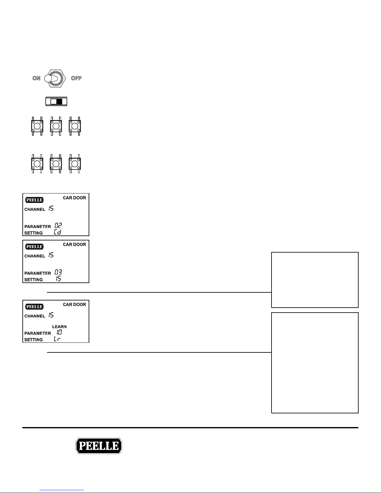
5.0 COMMISSIONING
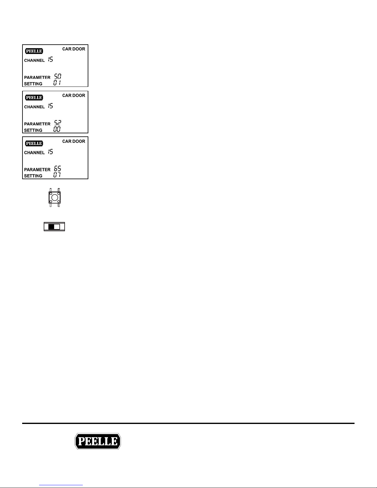
5.1 CAR DOOR COMMISSIONING
Make sure all Landing Doors and Car Doors are adjusted and run freely by hand in the door guides without
binding or sticking.
1. Turn power ON
AUTO
OPEN CLOSE RET
_
+
Tweaks
Tweaks
IND
CAM
ENTER
2. Set AUTO<>IND switch to IND
3. Using the OPEN, CLOSE and RETCAM cam buttons, ensure the car door operator(s) and
retiring cam motor(s) are phased for correct rotation. If a motor rotates in the wrong direction,
switch any two of the three motor wires
4. To begin, cycle through parameters by pressing the - & + buttons. Once the desired parameter
is displayed, press the ENTER button to access the setting for that parameter. Change the setting
by pressing the - & + buttons. Once the desired setting is displayed, press the ENTER button to
save the setting. Parameters can only be modied in IND mode.
5. Change parameter 02 to “Cd” setting.
e LCD display should now read “CAR DOOR”.
6. Use parameter 03 default “CHANNEL 15” for the rst car
door . For each additional car door , change parameter 03 to
a dierent channel. e LCD display will show what channel
has been selected.
7. Change parameter 10 to “Lr” setting. Press ENTER to begin
learn cycle. Prior to learn, car door can be in any position. e
learn cycle will fully close and then fully open. Once the car
door is fully open, the learn cycle is complete and the ashing
“LEARN” indicator on the LCD will turn o.
If car door stalls before learn
is complete, set parameter
12 to HD. Re-run the learn
cycle. Adjust speeds to suit
to ensure car door does not
slam.
If car door stalls during
operation (normal operation
or nudging), set parameter
12 to HD. Adjust speeds to
suit to ensure car door does
not slam.
THE PEELLE COMPANY
FREIGHT DOORSICAR GATESICAR ENCLOSURES
29
If retiring cam top assembly
does not completely li
retiring cam bottom
assembly, set parameter 70
to 10.
Guide No.
254-EN
VERSION:
WIRELESS CONTROLLER & BRIDGE
INSTALLATION & INTERFACE GUIDE
Date:
Mar 07 / 2018
Page 34
TECHNICAL SUPPORT 1-800-787-5020 ext 275
®
CLOSE
8. Set parameter 50 to “01” for CAN_Bridge Operation
9. Set parameter 52 to “00” for Front Car Door or “01” for Rear Car Door.
10. Set parameter 65 to “07” for Dual Light Curtain Test Output setting. see section 3.8 on page
20.
Note see output USER 1
L
11. Press and hold the CLOSE button to
close the door.
AUTO
IND
12. Set AUTO<>IND switch to AUTO.
THE PEELLE COMPANY
FREIGHT DOORSICAR GATESICAR ENCLOSURES
30
Guide No.
VERSION:
WIRELESS CONTROLLER & BRIDGE
INSTALLATION & INTERFACE GUIDE
Date:
Mar 07 / 2018
254-EN
Page 35
TECHNICAL SUPPORT 1-800-787-5020 ext 275
®
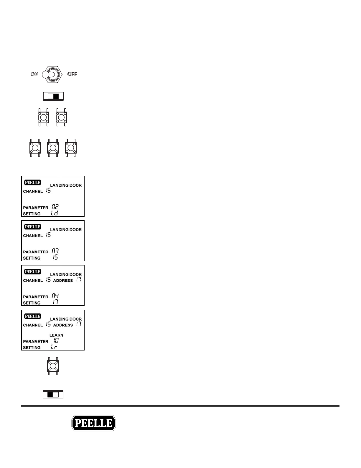
5.2 LANDING DOOR COMMISSIONING
• Ensure Landing Door interlock is mechanically unlocked. Ideally car is level at oor with retiring cam extended
• Ensure all EUD switches are set to the SET position
1. Turn power ON
AUTO
OPEN CLOSE
_
IND
ENTER
+
2. Set AUTO<>IND switch to IND
3. Using the OPEN and CLOSE buttons, ensure the landing door operators are phased for correct
rotation. If a motor rotates in the wrong direction, switch any two of the three motor wires.
4. To begin, cycle through parameters by pressing the - & + buttons. Once the desired parameter
is displayed, press the ENTER button to access the setting for that parameter. Change the setting
by pressing the - & + buttons. Once the desired setting is displayed, press the ENTER button to
save the setting. Parameters can only be modied in IND mode.
5. Change parameter 02 to “Ld” setting.
e LCD display should now read “landing door”.
If you have “Extra High Torque Door Operators” (see pg 7)
Set Slave controller to SL, no further commissioning of the slave controller is required.
Commission the associated master controller normally.
6. Change parameter 03 to match the channel of the adjacent car door. All the landing doors for
the front line must have the same channel as the front car door. e LCD display will show what
channel has been selected.
7. Change parameter 04 to address the landing door. Use “ADDRESS 01” for the lowest door in a
line of doors. Each additional landing door in line should be addressed in sequence (01, 02, 03
Etc). e LCD display will show what address has been selected.
8. Change parameter 10 to “Lr” setting. Press ENTER to begin learn cycle. Prior to learn, Landing
Door can be in any position. e learn cycle will fully close and then fully open. Once the
Landing Door is fully open, the learn cycle is complete and the ashing “LEARN” indicator on
the LCD will turn o.
9. Press and hold the CLOSE button to close
the door.
CLOSE
AUTO
IND
10. Set AUTO<>IND switch to AUTO.
THE PEELLE COMPANY
FREIGHT DOORSICAR GATESICAR ENCLOSURES
31
Guide No.
254-EN
VERSION:
WIRELESS CONTROLLER & BRIDGE
INSTALLATION & INTERFACE GUIDE
Date:
Mar 07 / 2018
Page 36
TECHNICAL SUPPORT 1-800-787-5020 ext 275
®
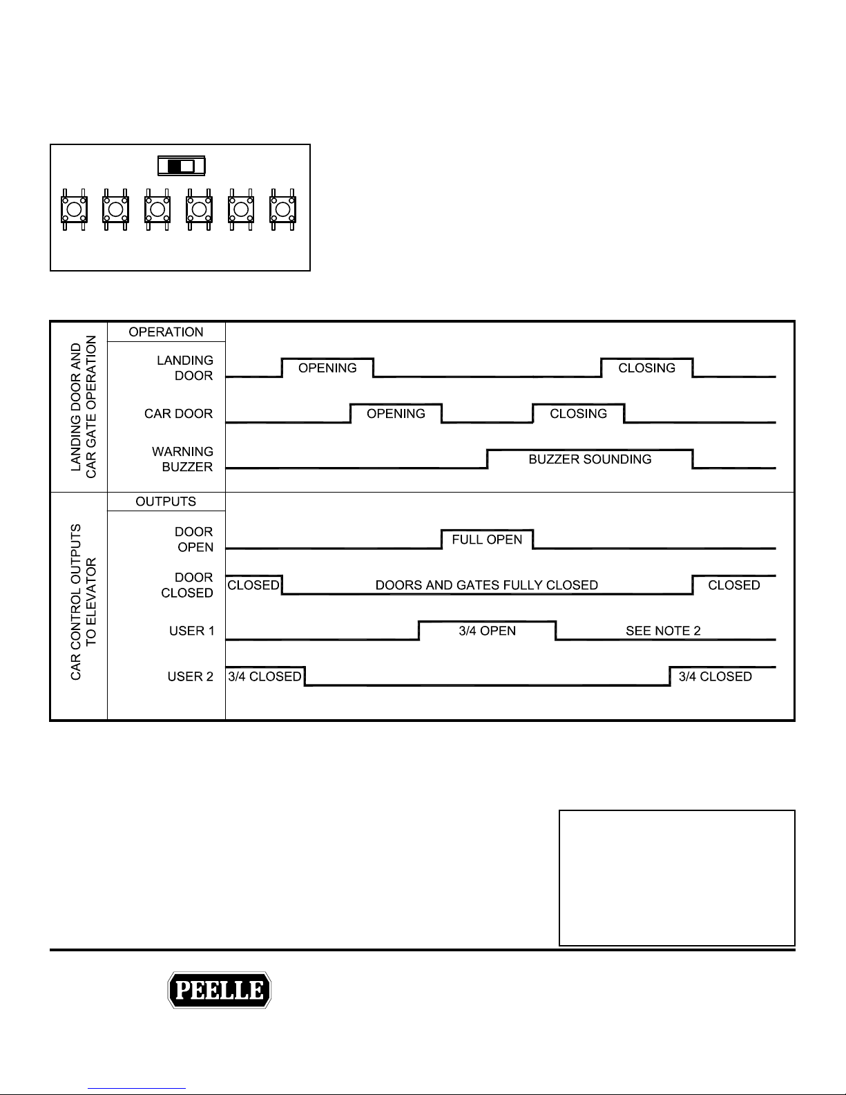
5.3 OPERATION AND TESTING - FROM THE CAR DOOR CONTROLLER
With the CAN connection from the bridge controller removed, test the following Sequence of Operation using the
OPEN, CLOSE and RETCAM buttons on the car door controller from the top of the car.
AUTO
CLOSEOPEN ENTER
5.4 SEQUENCE OF OPERATION
RET
CAM
IND
_
+
1. Remove the CAN connector to the controller
2. Make sure the controllers are set to AUTO
3. Use the OPEN, CLOSE and RETCAM buttons to test the door and
car door and retiring cam sequence of operation.
4. Reconnect the CAN connector.
For USER 1 and 2 options, see parameter 65 and 85
L
5.5 POWER UP MODE / LOSS OF POWER
After power-up with the elevator car at a landing, upon automatic initiation
of either open or close, the landing door and car door will operate at learn
speed until the nal open or closed position is reached and held for 1
second. The control will reset the learned prole and initiate DOOR OPEN
or DOOR CLOSED output. All un-zoned landing door controllers will
power up to normal prole See Parameter 93.
THE PEELLE COMPANY
FREIGHT DOORSICAR GATESICAR ENCLOSURES
32
Attention!
Landing door and Car door
settings and speed proles are
retained by the controller when
power is removed. It is not
necessary to relearn the opening.
Guide No.
VERSION:
WIRELESS CONTROLLER & BRIDGE
INSTALLATION & INTERFACE GUIDE
Date:
Mar 07 / 2018
254-EN
Page 37
TECHNICAL SUPPORT 1-800-787-5020 ext 275
®
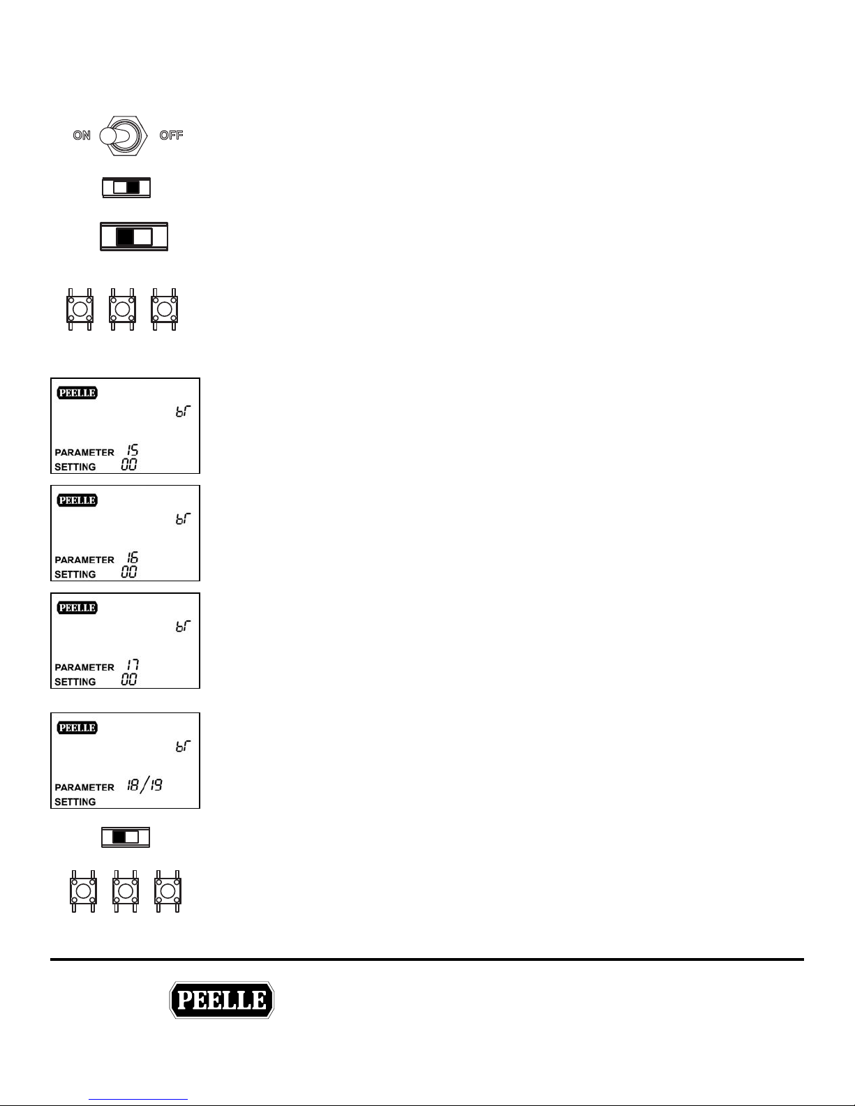
5.6 BRIDGE COMMISSIONING
Complete this commissioning after door operation testing, section 5.3
1. Turn power ON
AUTO
_
IND
REARFRONT
ENTER
+
2. Set AUTO<>IND switch to IND
3. Set FRONT<>REAR switch to desired setup. Both front and rear are commissioned
independently.
4. To begin, cycle through parameters by pressing the - & + buttons. Once the desired parameter
is displayed, press the ENTER button to access the setting for that parameter. Change the setting
by pressing the - & + buttons. Once the desired setting is displayed, press the ENTER button to
save the setting. Parameters can only be modied in IND mode.
5. Set parameter 15 to desired Auto Close time. Setting ”00” Auto Close is disabled.
• Auto Close set times: 30, 45, 60, 90, 120, 150, 180, 300 seconds.
6. Set parameter 16 to elevator code jurisdiction.
• New York City RS18 = “01”
• All others = “00”
7. Set parameter 17 for single or dual light curtains.
• Single Light Curtain = “00”
• Dual Light Curtains (2010 code compliance) = “01”
Also make sure to change your Car Door Controller Parameters 65 to “07” for dual
L
light curtains.
8. If required select USER1 or USER2 for desired relay output. See section Bridge Parameters,
and elevator control prints.
• USER 1 = Parameter 18
• USER 2 = Parameter 19
AUTO
OPEN CLOSE RET
IND
CAM
9. Set AUTO<>IND switch to AUTO.
10. Using the OPEN, CLOSE and RETCAM cam buttons, ensure the doors are functioning from
the Bridge Controller.
THE PEELLE COMPANY
FREIGHT DOORSICAR GATESICAR ENCLOSURES
33
Guide No.
254-EN
VERSION:
WIRELESS CONTROLLER & BRIDGE
INSTALLATION & INTERFACE GUIDE
Date:
Mar 07 / 2018
Page 38
TECHNICAL SUPPORT 1-800-787-5020 ext 275
®
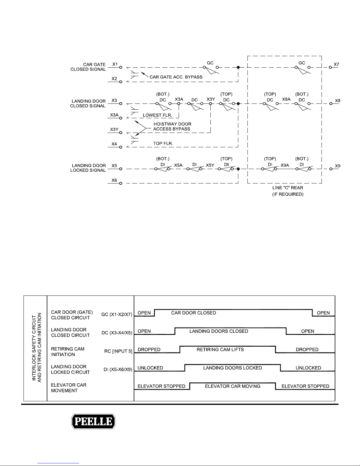
5.7 LANDING AND CAR DOOR INTERLOCKING CIRCUITS
Wiring
Note: The following interlock safety circuit wiring is for reference only.
REFER TO THE ELEVATOR PRINTS FOR PROPER INTERLOCK WIRING.
Elevator Control Operation
1) All DC (hoistway door closed) and GC (car gate closed) contacts should be connected in series and that the
contacts be made when the doors and gates are closed.
2) All DI (hoistway door lock) contacts should be connected in series and the contacts be made when all doors
are locked.
When the elevator controller is signaled, “all doors closed” through the DC and GC circuits, the elevator controller
may initiate retiring cam operation (see Retiring Cam Initiation Contact). Initiation will cause the retiring cam
face to retire (lift). When the interlock roller is no longer depressed by retiring cam, hoistway door locking
action takes place and the elevator controller is signaled, “all doors locked” through the Di circuit. The elevator
controller shall not allow the elevator car to run unless all DC (hoistway door closed) and GC (gate closed) and
DI (hoistway door locking) contacts are made.
Sequence of Operation
THE PEELLE COMPANY
FREIGHT DOORSICAR GATESICAR ENCLOSURES
34
Guide No.
VERSION:
WIRELESS CONTROLLER & BRIDGE
INSTALLATION & INTERFACE GUIDE
Date:
Mar 07 / 2018
254-EN
Page 39
TECHNICAL SUPPORT 1-800-787-5020 ext 275
®
6.0 CONTROLLER SETTINGS
A
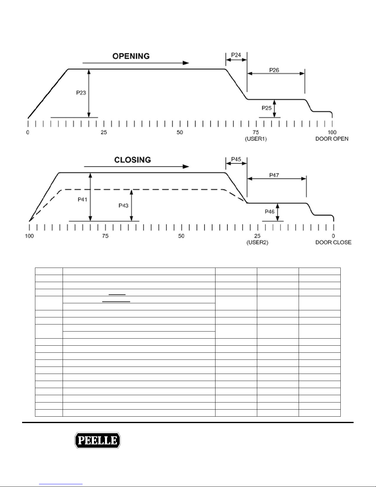
A
6.1 DOOR MOTION PROFILES
6.2 CAR & LANDING DOOR CONTROLLER PARAMETERS
Parameter Description Range Landing Pre Set Car Pre Set
Reset Overload (00 = Do not reset, 01 = Reset)
1
Controller Type: Car Door, Landing Door, Slave
2
Channel: set a unique Channel for each line of doors
3
Floor: set a unique Floor address for each Landing Door
4 00-30 00
(note: 00 is not a valid address)
Learn Command: used to learn the opening
10
Learn Speed: set learn and power-up speed
11
Car Door Duty: increase the car door duty
12 Sd-Hd N/A Sd
Sd = Standard Duty, Hd = Heavy Duty
Open High Speed: set the opening high speed
23
Open Deceleration Zone: set distance of deceleration ramp
24
Open Low Speed: set low speed open
25
Open Low Speed Zone
26
Open Hold Torque: set the hold open torque
27
Close High Speed: set the closing high speed
41
Close High Speed Torque Limit
42
Close Nudging Speed
43
Close Nudging Speed Torque Limit
44
Close Deceleration Zone: set distance of deceleration ramp
45
Close Low Speed: set low speed close
46
00-01 00 00
Cd,Ld,SL Ld Ld
11-22 15 15
Lr or -- -- --
40-70 40 40
20-99 99 99
00-30 10 10
20-99 50 30
00-30 10 10
00-50 25 20
20-99 99 85
30-99 99 99
30-70 N/
30-99 N/
00-30 10 10
20-99 50 30
N/A
50
99
THE PEELLE COMPANY
FREIGHT DOORSICAR GATESICAR ENCLOSURES
35
Guide No.
254-EN
VERSION:
WIRELESS CONTROLLER & BRIDGE
INSTALLATION & INTERFACE GUIDE
Date:
Mar 07 / 2018
Page 40
TECHNICAL SUPPORT 1-800-787-5020 ext 275
®
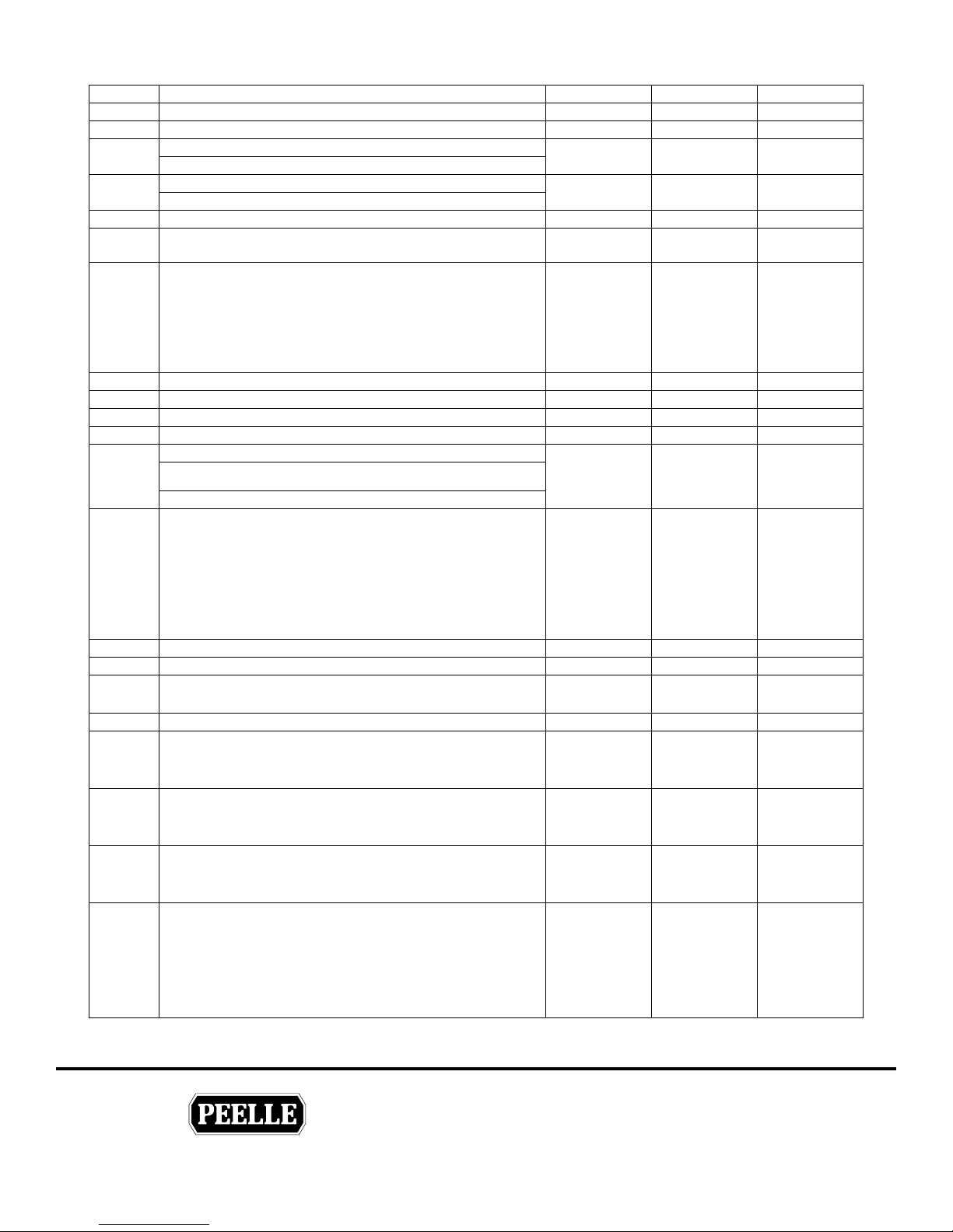
Parameter Description Range Landing Pre Set Car Pre Set
A
A
Close Low Speed Zone: set distance of low speed zone
47
Close Hold Torque: set the hold close torque
48
Control Interface: set discrete or CAN bus interface
50 00-01 N/A
00 = discrete, 01 = CAN
Car Door Designation: 00 = Front, 01 = Rear
52 00-01 N/A 00
(only displayed if Parameter 50 = 01)
CmcMedia: 00 = RF, 01 = Wired RS_485
53
USING AS REPLACEMENT CONTROLLER
54
If Parameter 80 is 18 or lower change Parameter 54 to 01
Lost Communication Reaction Time
04 = 0.4 sec
05 = 0.5 sec
.
55
.
.
18 = 1.8 sec
Deceleration rate
60
Acceleration rate
61
USER 2 Close Limit: set position of the user door close limit
62
USER 1 Open Limit: set position of the user door open limit
63
User Limits Setting:
00 = landing door USER limit + car door USER limit sets USER relay
64 00-01 N/A 00
output on car door controller
01 = car door USER limit sets USER relay output on car door controller
USER 1 options
00 = USER1 POSITION
01 = USER2 POSITION
02 = ZONE
03 = BUZZ / STROBE
65
04 = DOOR OPEN POSITION
05 = DOOR CLOSED POSITION
06 = AUX2 INPUT
07 = TEST OUTPUT (BRIDGE OPTION ONLY)
Retiring Cam Ramp Up Time (0.1 second increments)
70
Retiring Cam Ramp Down Time (0.1 second increments)
71
Software Version (read only)
80
Radio Strength
81
Motor Duty Control
00 = Disabled (contact Peelle if used)
82
01 = Standby Duty
02 = Increased Duty
Motor Overload Control
00 = Disabled (contact Peelle if used)
83
01 = Default Threshold
02 = Increased Threshold
Drive Over Temperature Control
00 = Disabled (contact Peelle if used)
84
01 = Default Threshold
02 = Increased Threshold
USER 2 options
00 = USER 2 POSITION
01 = USER 1 POSITION
02 = ZONE
85
03 = BUZZ / STROBE
04 = DOOR OPEN POSITION
05 = DOOR CLOSED POSITION
06 = AUX2 INPUT
00-20 10 10
00-50 25 20
00-01 00 00
00-01 00 00
04-18 10 10
01-10 03 03
01-10 03 03
70-99 75 75
70-99 75 75
00-07 03 00
00-20 N/
00-20 N/
2 digits
Software
Version
Software
Version
01-31 31 31
00-02 01 01
00-02 01 01
00-02 01 01
00-06 03 00
00
00
00
THE PEELLE COMPANY
FREIGHT DOORSICAR GATESICAR ENCLOSURES
36
Guide No.
254-EN
VERSION:
WIRELESS CONTROLLER & BRIDGE
INSTALLATION & INTERFACE GUIDE
Date:
Mar 07 / 2018
Page 41
TECHNICAL SUPPORT 1-800-787-5020 ext 275
®
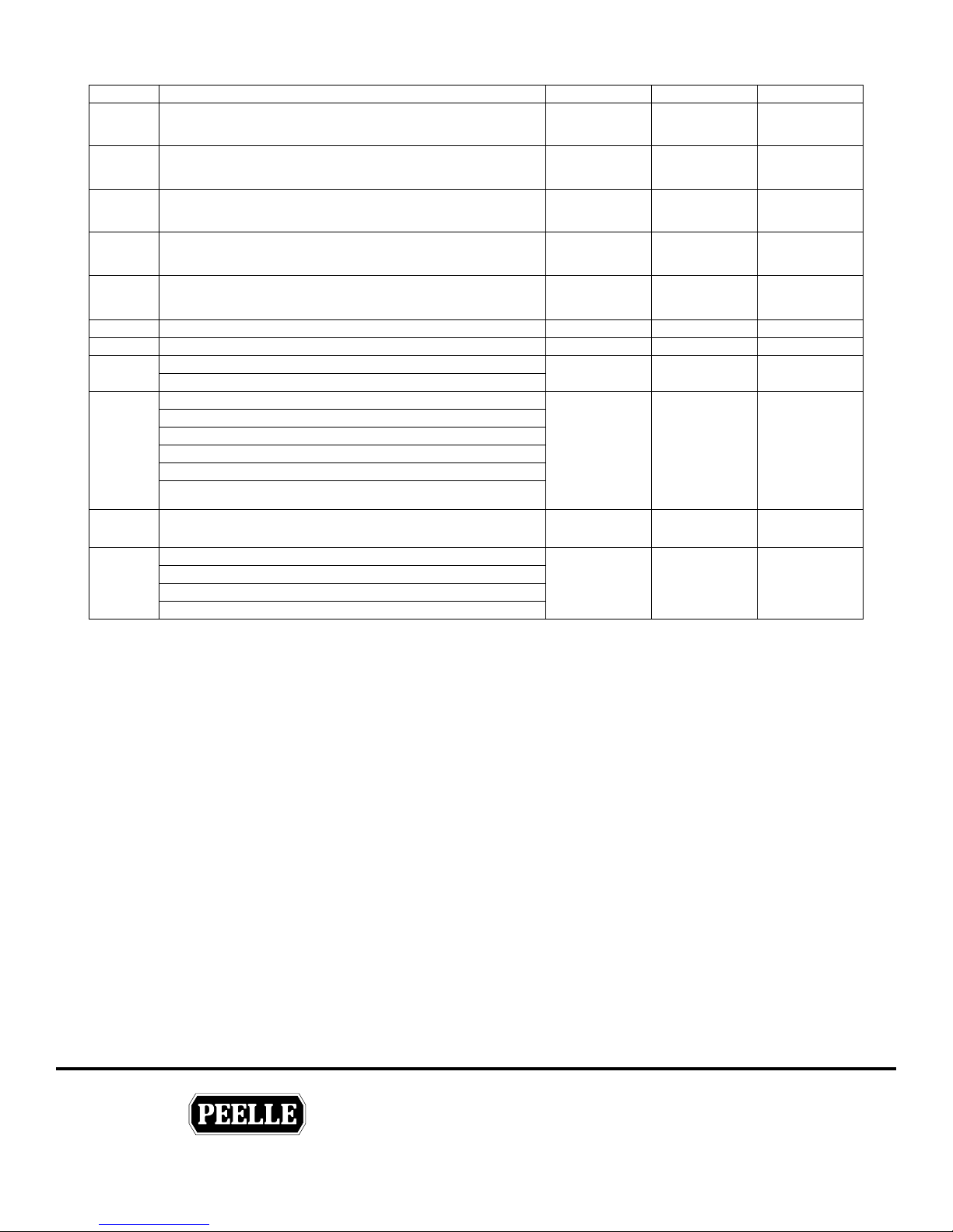
Parameter Description Range Landing Pre Set Car Pre Set
Retiring Cam Startup Torque
86
Only applicable if P70 or P71 is >0
Fast Open / Close
00 = Fast close only
87
01 = Fast open and close
Car Door Aux2 Input Option
00 = Disabled
88
01 = Independent Car Door Operation with input ON
Momentary Door Open / Door Close Option
00 = Constant DO and DC operation
89
01 = Momentary DO and DC operation
Power Up landing door speed (unzoned only)
00 = learn speed until final open/close limit
93
01 = normal profile speed
Buzzer Output: 00 = Pulsing, 01 = Continuous
94
Close Input Buzzer Control: 00 = Disabled, 01 = Enabled
95
Hall Stop Button Input:
96 00-01 00 N/A
00 = Normally Open, 01 = Normally Closed
Power-Up Settings:
01 – Door Closed = 1, Door Open = 1;
02 – Door Closed = 1, Door Open = 0;
97 01-03 02 02
03 – Door Closed = 0, Door Open = 0;
If zoned, both Door Closed and Door Open = 0, regardless of selection.
Condition of outputs is established automatically after opening or closing
cycle
Show Cycle Counter
98
Restore Factory Default Settings
00 – Exit without saving
99 00-02 00
01 – Restore all Motor parameters (#20 – 97)
02 – Restore all parameters (#2 – 97)
50-99 N/A 50
00-01 N/A 00
00-01 N/A 00
00-01 N/A 00
00-01 01 N/A
00-01 01 00
00-01 01 01
6 digits
Cycle
Counter
Cycle
Counter
00
N/A – Not available
Speeds are expressed as a percentage of full speed. Zone is expressed as a percentage of total travel.
Torque is expressed as a percentage of nominal voltage for corresponding speed.
THE PEELLE COMPANY
FREIGHT DOORSICAR GATESICAR ENCLOSURES
37
Guide No.
254-EN
VERSION:
WIRELESS CONTROLLER & BRIDGE
INSTALLATION & INTERFACE GUIDE
Date:
Mar 07 / 2018
Page 42
TECHNICAL SUPPORT 1-800-787-5020 ext 275
®
7
6.3 BRIDGE CONTROLLER PARAMETERS
Bridge Controllers will show a “br” on the LCD display
L
Parameter Description Range Bridge Pre Set
Auto Close Timer
00 = Disabled
15
30 - 300 = Enabled time in seconds (30, 45, 60, 90, 120, 150, 180, 300)
New York City Fire Service
00 = Disabled
16
01 = Enabled
Dual Light Curtains (Test Output)
00 = Disabled
17
01 = Enabled
Note: Also set parameter 65 on Car Door Controller to 0
USER 1 options
00 = USER 1 POSITION - FRONT
01 = USER 2 POSITION - FRONT
02 = ZONE - FRONT
03 = BUZZ / STROBE - FRONT
04 = DOOR OPEN POSITION - FRONT
06 = AUX 2 INPUT - FRONT
18
07 = LIGHT CURTAIN TEST OUTPUT (BRIDGE OPTION ONLY)
08 = USER 1 POSITION - REAR
09 = USER 2 POSITION - REAR
10 = ZONE - REAR
11 = BUZZ / STROBE - REAR
12 = DOOR OPEN POSITION - REAR
13 = AUX 2 INPUT - REAR
USER 2 options
00 = USER 1 POSITION - FRONT
01 = USER 2 POSITION - FRONT
02 = ZONE - FRONT
03 = BUZZ / STROBE - FRONT
04 = DOOR OPEN POSITION - FRONT
06 = AUX 2 INPUT - FRONT
19
07 = LIGHT CURTAIN TEST OUTPUT (BRIDGE OPTION ONLY)
08 = USER 1 POSITION - REAR
09 = USER 2 POSITION - REAR
10 = ZONE - REAR
11 = BUZZ / STROBE - REAR
12 = DOOR OPEN POSITION - REAR
13 = AUX 2 INPUT - REAR
Software Version (Read Only)
20
Restore Factory Default Settings
00 – Exit without saving
21 00-01 00
01 – Restore all Deafult parameters
00-300 00
00-01 00
00-01 00
00-13 00
00-13 00
2 digits
Software
Version
THE PEELLE COMPANY
FREIGHT DOORSICAR GATESICAR ENCLOSURES
38
Guide No.
254-EN
VERSION:
WIRELESS CONTROLLER & BRIDGE
INSTALLATION & INTERFACE GUIDE
Date:
Mar 07 / 2018
Page 43
TECHNICAL SUPPORT 1-800-787-5020 ext 275
®
7.0 TROUBLESHOOTING
7.1 INDEPENDENT MODE
PEELLE ONLY OPERATION - USED FOR COMMISSIONING AND INDIVIDUAL
LANDING/CAR DOOR OPERATION
(AUTO-IND slider switch set to IND)
Problem Possible Cause Action
AUTO-IND slider not set to IND Set AUTO-IND slider to IND
No operation from
OPEN/CLOSE pushbutton
No operation from RETCAM
pushbutton
Slow speed Landing/Car Door
operation only
Wiring problem to Landing Door motor output
or Car Door selector relay output
Flashing LCD “OVERLOAD” icon
Constant LCD “OVERLOAD” icon
Controller type not set to Car Door (CD) Ensure parameter P02 is set to “CD”
Wiring problem to Car Door selector relay
output
LCD “LEARN” flashing
See page 6 for Landing Door motor wiring
See pages 15 & 16 for Car Door/Retiring Cam
motor wiring
Duty timer for motor has been exceeded. Cool
down period required for motor regeneration. If
condition persists, increase duty timer. See
parameters P72 & P82.
Note: increasing duty timer may shorten motor
life
Check Landing Door motor output or Car Door
selector relay output for short circuit to ground
See page 6 for Landing Door motor wiring
See pages 15 & 16 for Car Door/Retiring Cam
motor wiring
Acknowledge “OVERLOAD” by setting
parameter P01 to 01
See pages 15 & 16 for Car Door/Retiring Cam
motor wiring
Operational profile not learned. Set parameter
P10 to “Lr” to initiate learn sequence
Encoder set screw loose Ensure set screw is tight on encoder shaft
Landing/Car door runs for 12”
then stops
Retiring Cam not fully pulling
back
Encoder wiring problem
Mechanical problem with bottom assembly
(face)
Mechanical problem with top assembly (motor) Ensure pulley belt has 3/4” of deflection
Mechanical problem with full assembly
THE PEELLE COMPANY
FREIGHT DOORSICAR GATESICAR ENCLOSURES
39
See page 5 for Landing Door encoder wiring
See pages 14 for Car Door encoder wiring
Move door manually and check that encoder
count on LCD is changing
Ensure bottom assembly moves freely on pivot
pins
Ensure connecting rod is parallel to bottom
assembly (face) and top assembly (motor)
Ensure when pulling back that pickup arm on
top assembly starts at 6 o’clock and rotates
towards middle of car to either 9 o’clock or 3
o’clock (depending on rotational direction)
Guide No.
254-EN
VERSION:
WIRELESS CONTROLLER & BRIDGE
INSTALLATION & INTERFACE GUIDE
Date:
Mar 07 / 2018
Page 44
TECHNICAL SUPPORT 1-800-787-5020 ext 275
®
7.2 AUTOMATIC MODE
PEELLE ONLY OPERATION - USED FOR COMBINED LANDING AND CAR DOOR
OPERATION
(AUTO-IND slider switch set to AUTO)
Problem Possible Cause Action
No operation from
OPEN/CLOSE pushbutton
AUTO-IND slider not set to AUTO
Elevator not in Landing Door zone
LCD “ZONE” icon not on at either Landing
Door controller or corresponding Car Door
controller
LCD “ANTENNA” icon not on (or flashing) at
zoned Landing Door controller or
corresponding Car Door controller
LCD “EUD” icon on (or flashing) at Landing
Door controller and flashing at corresponding
Car Door controller
LCD “MULTIZONE” icon on at Landing Door
controller and corresponding Car Door
controller
Flashing LCD “OVERLOAD” icon
Constant LCD “OVERLOAD” icon
Set AUTO-IND slider to AUTO
All controllers must be set to AUTO.
Ensure retiring cam bottom assembly is on
Landing Door roller arm
Ensure Input 3 is on at Landing Door controller.
See page 9.
Ensure Landing Door channel matches Car
Door channel. Adjust parameter P03 if
necessary
Ensure Landing Door address is unique and not
set to 00. Adjust parameter P04 if necessary
Constant LCD “EUD” icon = EUD is in set
position at current landing
Flashing LCD “EUD” icon = EUD is in set
position at another landing on the same channel
See page 8.
Check all interlock zone micro switches. Only
one zone micro switch can be on at a time on
one channel.
Duty timer for motor has been exceeded. Cool
down period required for motor regeneration. If
condition persists, increase duty timer. See
parameters P72 & P82.
Note: increasing duty timer may shorten motor
life
Check Landing Door motor output or Car Door
selector relay output for short circuit to ground
See page 6 for Landing Door motor wiring
See pages 15 & 16 for Car Door/Retiring Cam
motor wiring
Acknowledge “OVERLOAD” by setting
parameter P01 to 01
THE PEELLE COMPANY
FREIGHT DOORSICAR GATESICAR ENCLOSURES
40
Guide No.
254-EN
VERSION:
WIRELESS CONTROLLER & BRIDGE
INSTALLATION & INTERFACE GUIDE
Date:
Mar 07 / 2018
Page 45

TECHNICAL SUPPORT 1-800-787-5020 ext 275
®
p
7.3 ELEVATOR INTERFACE OPERATION
Problem Possible Cause Action
Are LCD input icons on Bridge controller?
If not check the folowing:
If Peelle power is used to power Peelle inputs,
missing jumper from Input Com terminal to V–
terminal on Car Door controller
Elevator controller is sending
outputs to Bridge controller but
no Landing / Car Door
operation in open or close
direction
If external power is used to power Peelle inputs,
missing external power reference wire on Input
Com terminal on Car Door controller
LD & CD on Auto?
Add jumper from Input Com to V-. See page 22
Ensure external power reference is wired to Input
Com. See page 22
Ensure external power reference is wired to Input
Com. See page 22
Note: ensure no connections to Peelle V+/V-
Ensure parameter P50 is set to 00 on Car Door
Controller
Bridge controller is sending
signal to car door controller but
no Landing/Car Door operation
in open or close direction
Is antenna icon solid on Bridge controller?
If not...
Are LCD input icons on Car Door controller?
If not check the folowing:
If Peelle power is used to power Peelle inputs,
missing jumper from Input Com terminal to V–
terminal on Car Door controller
If external power is used to power Peelle inputs,
missing external power reference wire on Input
Com terminal on Car Door controller
Landing Door stop input on
Landing/Car door stopped before final
open/close
Check CAN connection from Bridge Controller to
Car Door Controller
Add jumper from Input Com to V-. See page 22
Ensure external power reference is wired to Input
Com. See page 22
Note: ensure no connections to Peelle V+/VEnsure parameter P50 is set to 00.
Ensure input 5 is off on Landing Door controller.
See page 10
See Automatic Mode chart
Door may be mechanically obstructed. Fix
obstruction.
If there is not enough power in slow speed for final
open or final close, increase the following
arameter(s) in multiples of 5 until fixed:
Open direction - P27
Close direction - P48
Bridge controller is sending
signals to car door controller but
no Landing/Car Door operation
in close direction
Light curtain obstructed
THE PEELLE COMPANY
FREIGHT DOORSICAR GATESICAR ENCLOSURES
41
Check light curtain alignment
For dual light curtains ensure P65 is set to 047 on
car door controller
Guide No.
254-EN
VERSION:
WIRELESS CONTROLLER & BRIDGE
INSTALLATION & INTERFACE GUIDE
Date:
Mar 07 / 2018
Page 46
TECHNICAL SUPPORT 1-800-787-5020 ext 275
®
7.4 ERROR CODES
If the setting is ashing from encoder count (5 digits) to and error code (4 digits) refer to
the following.
How to read
Example: Car Door Error 06 10
The rst two digits are the sum of the rst four possible errors.
06 = 02 (car door motor run error) + 04 (car motor over duty)
The last two digits are the sum of the last four possible errors.
10 = 02 (EUD error) + 08 (lost zone)
Car door error codes - last two digits
01 - Not used
02 - EUD error
04 - Multi Zone error
08 - Lost zone
Car door error codes - rst two digits
01 - Landing door motor run error
02 - Car door motor run error
04 - Car motor over duty
08 - retiring cam motor over duty
Landing door error codes - rst two digits
01 - Landing door motor run error
02 - Not used
04 - Landing door motor over duty
08 - Not used
To clear error codes cycle the AUTO-IND slider switch
Landing door error codes - last two digits
01 - Not used
02 - EUD input set
04 - Multi Zone error
08 - Lost zone
AUTO
IND
THE PEELLE COMPANY
FREIGHT DOORSICAR GATESICAR ENCLOSURES
42
Guide No.
254-EN
VERSION:
WIRELESS CONTROLLER & BRIDGE
INSTALLATION & INTERFACE GUIDE
Date:
Mar 07 / 2018
Page 47
TECHNICAL SUPPORT 1-800-787-5020 ext 275
®
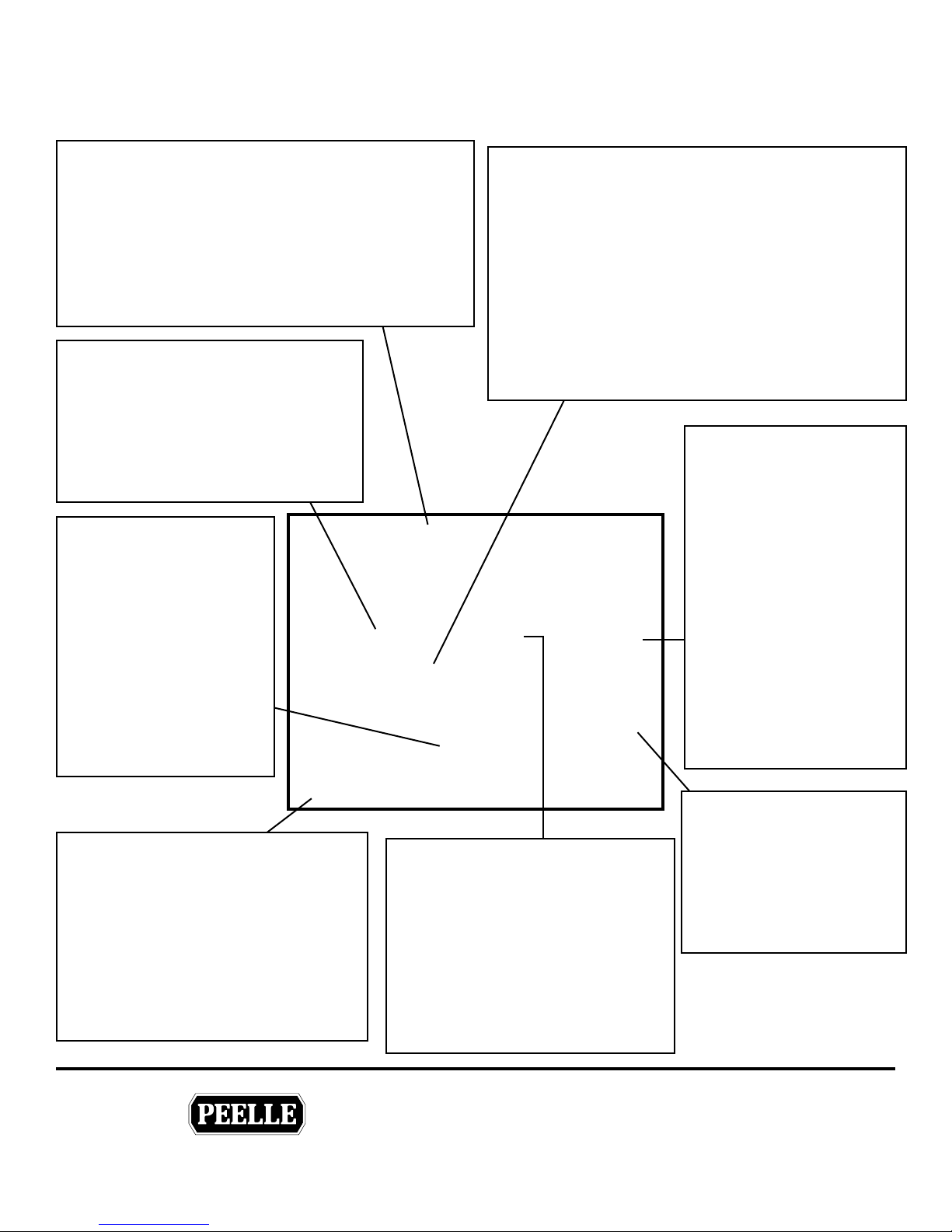
7.5 LANDING DOOR LCD
Radio Communication
Antenna is ON solid when elevator is at a oor and
•
door is ZONED
Antenna is ON solid when EUD is SET whether
•
door is ZONED or not
Antenna is OFF when elevator is not ZONED
•
For intermittent ashing in ZONE adjust channel
•
selection
Multiple Zone
MULTIZONE indicator is shown
•
when two or more landing door
controllers are ZONED on the same
channel
Check zone switches and ZNS inputs
•
at landings
Number Display
Number display show
•
encoder count (door
position)
Approximately 0-50
•
for landing door closed
position
Full count for open
•
position
May ash fault codes for
•
Peelle Use
Motor Overload / Over Duty
OVERLOAD is ON solid when over current exists
•
at motor output
Check for shorts on motor line
◦
Check for shorts to ground
◦
Reset of overload is required; set parameter 01 to 01
•
and press ENTER to clear (must go to IND mode)
OVERLOAD is ashing when motor run time
•
exceeds duty
Let motor reset for 5 minutes
◦
Over Duty does not require reset
•
Landing Zone
Zone is ON solid when
•
elevator is at a oor with
retiring cam extended and
door unlocked
Input indicator 3 ZNS is
•
ON when door is ZONED
Zone and 3 are OFF
•
when doors are locked
and / or car is moving
between oors
Doors will not run if
•
ZONE is not made
Check ZNS and zone
•
switch
Input Indicators
1 HDO - Hall door open button
2 HDC - Hall door closed button
3 ZNS - Floor Zone switch
4 EUD - Emergency Unlocking Device
5 STOP - hall door stop button
6 AUX1 - Not Used
7 AUX2 - Not Used
8 RE - Hall door light curtain input
(where provided)
THE PEELLE COMPANY
FREIGHT DOORSICAR GATESICAR ENCLOSURES
Emergency Unlocking Device
EUD is ON solid when EUD is
•
SET at that oor
Input indicator 4 is ON when
•
EUD is SET at that oor
EUD is ashing when EUD is SET
•
at another oor on same channel
Doors will not run if any EUD is
•
SET on the same channel
43
Door Stop Sign
Door Stop Sign is ON
•
whenever motors are not
running
Door Stop Sign is OFF
•
when power is being
applied to motors
Guide No.
VERSION:
WIRELESS CONTROLLER & BRIDGE
INSTALLATION & INTERFACE GUIDE
Date:
Mar 07 / 2018
254-EN
Page 48

TECHNICAL SUPPORT 1-800-787-5020 ext 275
®
7.6 CAR DOOR LCD
Radio Communication
Antenna is ON solid when elevator is at a oor and
•
door is ZONED
Antenna is OFF when elevator is travelling
•
Antenna is Flashing Constant when elevator is not
•
ZONED
For intermittent ashing in ZONE adjust channel
•
selection
Multiple Zone
MULTIZONE error is shown when
•
two or more landing door controllers
are ZONED on the same channel
ZONED oor addresses are shown
•
in Number Display
Check ZONE switches and ZNS
•
inputs at landings
Number Display
Number display show
•
encoder count (car door
position)
Approximately 0-50 for
•
car door closed position
Full count for open
•
position
Will show oor addresses
•
in MULTIZONE error
Shows oor addresses
•
when and EUD is SET
May ash fault codes for
•
Peelle Use
Input Indicators
1 DO - Door open command from elevator
2 DC - Door closed command from elevator
3 SE - Close nudging command from elevator
4 DCM - Fast close command from elevator
5 RC - Retiring cam command from elevator
6 BUZZ - Close warning buzzer command
from elevator
7 AUX2 - Not Used
8 RE - Reversing edge input from car door
Motor Overload / Over Duty
OVERLOAD is ON solid when over current exists
•
at motor output
Check for shorts on motor line
•
Check for shorts to ground
•
Reset of overload is required; set parameter 01
•
to 01 and press ENTER to clear (must go to IND
mode)
OVERLOAD is ashing when motor run time
•
exceeds duty
Let motor reset for 5 minutes
•
Over Duty does not require reset
•
Emergency Unlocking Device
EUD is ashing when an EUD has
•
been SET
EUD is OFF when all landing
•
doors have been RESET
Floor addresses where EUD is
•
SET are shown in the Number
Display
Doors will not run if any EUD is
•
SET on the same channel
Landing Zone
Zone is ON solid when
•
elevator is at a oor with
retiring cam extended
and door unlocked
Zone is OFF when all
•
doors are locked and / or
car is moving between
oors
Doors will not run if
•
ZONE is not made
Check ZNS and zone
•
switch
Door Stop Sign
Door Stop Sign
•
is ON whenever
motor is not
running
Door Stop Sign is
•
OFF when power
is being applied to
motor
THE PEELLE COMPANY
FREIGHT DOORSICAR GATESICAR ENCLOSURES
44
Guide No.
VERSION:
WIRELESS CONTROLLER & BRIDGE
INSTALLATION & INTERFACE GUIDE
Date:
Mar 07 / 2018
254-EN
Page 49

TECHNICAL SUPPORT 1-800-787-5020 ext 275
®
7.7 BRIDGE LCD
FRONT or REAR Selector
• LCD shows indicators according to selector switch
• Parameters setting according to selector switch
FRONT
REAR
THE PEELLE COMPANY
FREIGHT DOORSICAR GATESICAR ENCLOSURES
45
Guide No.
VERSION:
WIRELESS CONTROLLER & BRIDGE
INSTALLATION & INTERFACE GUIDE
Date:
Mar 07 / 2018
254-EN
Page 50
TECHNICAL SUPPORT 1-800-787-5020 ext 275
®
8.0 TECHNICAL SPECIFICATIONS
Technical Data Specication
Input Power 5.5A @ 240V, 1.3 kW
Supply Voltage 208-240V, 1 Ø AC, 50/60Hz
Output Power 0-230V, 3 Ø AC, 4.2A, 0-60Hz
Output Motor 0.75 kW (1 HP)
Digital Inputs 8 provided, 12-30V, AC or DC
Encoder Input Incremental, NPN, 12VDC, 120 PPR
Relay Outputs 8 provided, Form C, 10A, 125VAC
Input Indicators LCD screen
Output Indicators LED
Enclosure Protection NEMA 1,4,4X (indoor use only) - IP 65
Temperature 40 Deg C Max
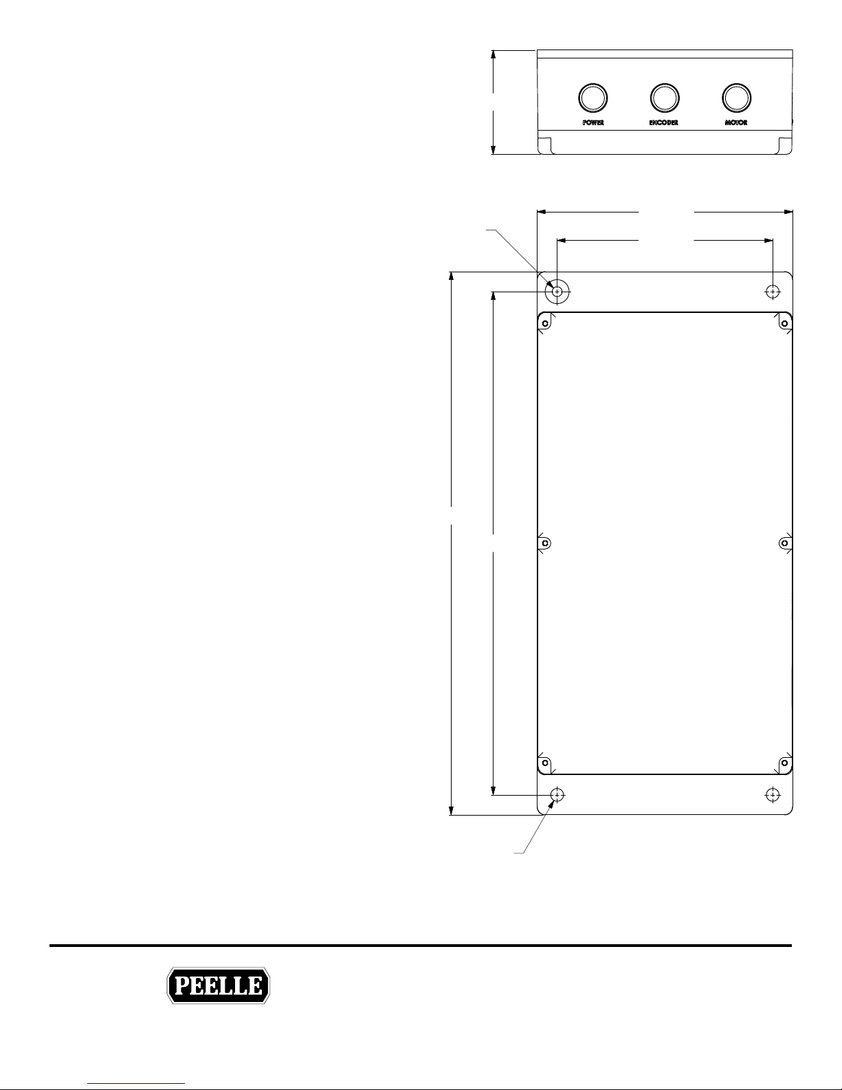
Dimensions 200mm x 430mm x 85mm (W x H x D)
Mounting Method 4 screw holes on outside perimeter
Equipment Class Digital Transmission System
Wireless Network 802.15.4 LR-WPAN standard
Wireless Frequency 2.4GHz
Wireless Output 0.094 Watts
Wireless Range 100m oor-to-oor up to 99 oors
User Interface On board pushbuttons with visual display
Visual Display 50mm x 40mm back-lit LCD
Parameters User adjustable with factory presets and defaults
Learn Adjustment Automatic by user parameter
Landing Door Address User selectable parameter
Car or Landing Door Type User selectable parameter
Fail Safe Condition Door Stop if communication lost
17.00 [432]
.31 [8]
3.26 [83]
8.00 [203]
6.75 [171]
Standards
Elevators and Lifts
ASME-A17.1/CSA-B44
ASME-A17.5/CSA-B44.1
EN 81
EN 12015 and EN12016
Telecommunication
FCC
Industry Canada
R&TTE Directive
Certication
ETL Listing and Certication Mark
FCC Grant of Equipment Authorization
Industry Canada Certicate of Acceptance
Declaration
This device complies with part 15 of the FCC rules. Operation is subject to the
following two conditions: (1) the device may not cause harmful interference, and
(2) the device must accept any interference received, including interference that
may cause undesired operation.
Modications not expressly approved by The Peelle Company Ltd. could void the
user’s authority to operate the equipment under FCC rules.
15.75 [400]
.40 [10]
THE PEELLE COMPANY
FREIGHT DOORSICAR GATESICAR ENCLOSURES
46
Guide No.
254-EN
VERSION:
WIRELESS CONTROLLER & BRIDGE
INSTALLATION & INTERFACE GUIDE
Date:
Mar 07 / 2018
Page 51

TECHNICAL SUPPORT 1-800-787-5020 ext 275
®
9.0 EC DECLARATION OF CONFORMITY
Manufacturer:
The Peelle Company Ltd.
195 Sandalwood Pkwy W.
Brampton, Ontario L7A 1J6
CANADA
W e, The Peelle Company Limited of Brampton, Ontario, declare that the product designated below complies with
the relevant fundamental requirements of Article 3 of the Lifts directive 2014/33/EU insofar as the product is used
as intended and the following standards applied:
Product: Wireless Freight Door Controller, 2.4GHz, 802.15.4 Transceiver Module
Manufactured by: The Peelle Company Ltd. Trade mark: Peelle
Model: WFDC 27451 Car Door, WFDC 27452 Landing Door
Environment of use: Residential, commercial and light industry
Standards:
-Lifts EN 81-20:2014 Safety rules for the construction and installation of lifts
EN 12015:2014 Electromagnetic compatibility – Emissions
EN 12016:2013 Electromagnetic compatibility – Immunity
EN 61000-6-1:2007 Electromagnetic compatibility (EMC)
-Telecommunication EN 50371, EN 301 489-1, EN 301 489-17, EN 300 440
Date of issue: MAY 2017
Place of issue: Brampton, Ontario, CA
Frank Leo P.Eng.
Engineering Manager
THE PEELLE COMPANY
FREIGHT DOORSICAR GATESICAR ENCLOSURES
47
Guide No.
VERSION:
WIRELESS CONTROLLER & BRIDGE
INSTALLATION & INTERFACE GUIDE
Date:
Mar 07 / 2018
254-EN
Page 52

TECHNICAL SUPPORT 1-800-787-5020 ext 275
®
THE PEELLE COMPANY
FREIGHT DOORSICAR GATESICAR ENCLOSURES
Guide No.
VERSION:
WIRELESS CONTROLLER & BRIDGE
INSTALLATION & INTERFACE GUIDE
254-EN
Date:
Dec 18 / 2017
 Loading...