

Page 1

Peek Traffic Model LPM-14-E
High Speed Low Power Modem
REFERENCE MANUAL
Peek Traffic, Inc.
©1996, Peek Traffic, Inc. All Rights Reserved Rev. 1, January 16, 1997
1500 North Washington Blvd. Sarasota FL 34236 (941) 366-8770
Page 2

TABLE OF CONTENT
1. GENERAL DESCRIPTION...................................................................................................................................................................1-1
1.1. INTRODUCTION................................................................................................................................................................ 1-1
1.2. FEATURES ........................................................................................................................................................................ 1-1
1.3. INDICATORS ..................................................................................................................................................................... 1-1
1.4. INSTALLATION.................................................................................................................................................................. 1-1
1.5. INSTALLATION.................................................................................................................................................................. 1-1
2. AT COMMAND SUMMARY.................................................................................................................................................................. 2-1
3. AT COMMAND SET .............................................................................................................................................................................3-1
3.1. AT COMMAND GUIDELINES............................................................................................................................................. 3-1
3.1.1. AT Commands, DTE Adaption....................................................................................................................3-1
3.1.2. AT Command Format ................................................................................................................................. 3-1
3.1.3. Escape Code Sequence..............................................................................................................................3-1
3.2. AT COMMAND SET ........................................................................................................................................................... 3-2
3.2.1. AT Commands............................................................................................................................................3-2
A/ - Re-execute Command.............................................................................................................. 3-2
AT= x - Write to Selected S-Register............................................................................................... 3-2
AT? - Read Selected S-Register ..................................................................................................... 3-2
A - Answer ......................................................................................................................................3-2
Bn - CCITT or Bell...........................................................................................................................3-2
Cn - Carrier Control.........................................................................................................................3-2
Dn - Dial..........................................................................................................................................3-3
En - Command Echo.......................................................................................................................3-4
Fn - Select Line Modulation.............................................................................................................3-4
Hn - Disconnect (Hang-Up).............................................................................................................3-4
In - Identification..............................................................................................................................3-5
Ln - Speaker Volume.......................................................................................................................3-5
Mn - Speaker Control...................................................................................................................... 3-5
Nn - Automode Enable....................................................................................................................3-5
On - Return to On-Line Data Mode..................................................................................................3-5
P - Set Pulse Dial Default................................................................................................................ 3-6
Qn - Quiet Results Codes Control................................................................................................... 3-6
Sn - Read/Write S-Register............................................................................................................. 3-6
T - Set Tone Dial Default................................................................................................................. 3-6
Vn - Result Code Form....................................................................................................................3-6
Wn - Connect Message Control ...................................................................................................... 3-7
Xn - Extended Result Codes:..........................................................................................................3-7
Table 3.1 Result Codes .................................................................................................................................................. 3-8
Yn - Long Space Disconnect........................................................................................................... 3-8
Zn - Soft Reset and Restore Profile................................................................................................. 3-9
3.2.2. AT& Commands..........................................................................................................................................3-9
&Cn - RLSD (DCD) Option.............................................................................................................. 3-9
&Dn - DTR Option........................................................................................................................... 3-9
&Fn - Restore Factory Configuration (Profile).................................................................................. 3-9
&Gn - Select Guard Tone.............................................................................................................. 3-10
&Jn - Telephone Jack Control....................................................................................................... 3-10
&Kn - Flow Control........................................................................................................................ 3-10
&Ln - Leased Line Operation......................................................................................................... 3-10
&Mn - Asynchronous/Synchronous Mode Selection......................................................................3-10
&Pn - Select Pulse Dial Make/Break Ratio.................................................................................... 3-11
i
Page 3

&Qn - Sync/Async Mode............................................................................................................... 3-11
&Rn - RTS/CTS Option................................................................................................................. 3-11
&Sn - DSR Override......................................................................................................................3-12
&Tn - Test and Diagnostics...........................................................................................................3-12
&V - Display Current Configuration and Stored Profiles................................................................. 3-12
&Wn - Store Current Configuration................................................................................................ 3-13
&Yn - Designate a Default Reset Profile........................................................................................3-13
&Zn=x - Store Telephone Number................................................................................................. 3-13
3.2.3. AT% Commands....................................................................................................................................... 3-14
%En - Enable/Disable Line Quality Monitor and Auto-Retrain or Fallback/Fall Forward................. 3-14
%L - Line Signal Level...................................................................................................................3-14
%Q - Line Signal Quality............................................................................................................... 3-14
3.2.4. AT\ Commands.........................................................................................................................................3-15
\Gn - Modem-to-Modem Flow Control (XON/XOFF) ......................................................................3-15
\Kn - Break Control........................................................................................................................ 3-15
\Nn - Operating Mode.................................................................................................................... 3-15
3.3. ERROR DETECTION AND DATA COMPRESSION COMMANDS................................................................................... 3-16
3.3.1. AT% Commands....................................................................................................................................... 3-16
%C - Enable/Disable Data Compression....................................................................................... 3-16
3.3.2. AT\ Commands.........................................................................................................................................3-16
\An - Select Maximum MNP Block Size......................................................................................... 3-16
\Bn - Transmit Break to Remote.................................................................................................... 3-16
3.4. MNP 10 COMMANDS....................................................................................................................................................... 3-17
3.4.1. AT) Commands......................................................................................................................................... 3-17
)Mn - Enable Cellular Power Level Adjustment..............................................................................3-17
*Hn - Link Negotiation Speed........................................................................................................3-17
-Kn - MNP Extended Services.......................................................................................................3-18
-Qn - Enable Fallback to V.22 bis/V.22..........................................................................................3-18
@Mn - Initial Cellular Power Level Setting..................................................................................... 3-18
:E - Compromise Equalizer Enable Command .............................................................................. 3-18
4. S-REGISTERS ..................................................................................................................................................................................... 4-1
4.1. FACTORY DEFAULTS....................................................................................................................................................... 4-1
4.2. S-REGISTER DEFINITIONS .............................................................................................................................................. 4-1
S0 - Number of Rings to Auto-Answer.............................................................................................4-2
S1 - Ring Counter............................................................................................................................4-2
S2 - Escape Character....................................................................................................................4-2
S3 - Carriage Return Character....................................................................................................... 4-2
S4 - Line Feed Character................................................................................................................4-2
S5 - Backspace Character .............................................................................................................. 4-2
S6 - Wait Time for Dial Tone Before Blind Dialing........................................................................... 4-2
S7 - Wait Time For Carrier After Dial............................................................................................... 4-2
S8 - Pause Time For Dial Delay...................................................................................................... 4-3
S9 - Carrier Detect Response Time.................................................................................................4-3
S10 - Lost Carrier To Hang Up Delay.............................................................................................. 4-3
S11 - DTMF Tone Duration.............................................................................................................4-3
S12 - Escape Prompt Delay (EPD)..................................................................................................4-3
S13 - Reserved...............................................................................................................................4-3
S14 - General Bit Mapped Options Status.......................................................................................4-3
S15 - Reserved...............................................................................................................................4-4
S16 - General Bit Mapped Test Options Status...............................................................................4-4
S17 - Reserved...............................................................................................................................4-4
S18 - Test Timer ............................................................................................................................. 4-4
ii
Page 4

S19 - AutoSync Bit Mapped Options............................................................................................... 4-4
S20 - AutoSync HDLC Address or BSC Sync Character................................................................. 4-4
S21 - V.24/General Bit Mapped Options Status...............................................................................4-4
S22 - Speaker/Results Bit Mapped Options Status ......................................................................... 4-4
S23 - General Bit Mapped Options Status.......................................................................................4-4
S24 - Sleep Inactivity Timer ............................................................................................................ 4-4
S25 - Delay To DTR........................................................................................................................4-4
S26 - RTS to CTS Delay ................................................................................................................. 4-5
S27 - Bit Mapped Options Status .................................................................................................... 4-5
S28 - Bit Mapped Options Status .................................................................................................... 4-5
S29 - Flash Dial Modifier Time........................................................................................................ 4-5
S30 - Disconnect Inactivity Timer.................................................................................................... 4-5
S31 - Bit Mapped Options Status .................................................................................................... 4-5
S32 - XON Character...................................................................................................................... 4-5
S33 - XOFF Character..................................................................................................................... 4-6
S34-S35 - Reserved........................................................................................................................ 4-6
S36 - LAPM Failure Control............................................................................................................. 4-6
S37 - Desired Line Connection Speed............................................................................................. 4-6
S38 - Delay Before Forced Hang Up...............................................................................................4-6
S39 - Flow Control Bit Mapped Options Status................................................................................4-7
S40 - General Bit Mapped Options Status.......................................................................................4-7
S41 - General Bit Mapped Options Status.......................................................................................4-7
S46 - Data Compression Control..................................................................................................... 4-7
S48 - V.42 Negotiation Action ......................................................................................................... 4-7
S82 - Break Handling Options......................................................................................................... 4-8
S86 - Call Failure Reason Code......................................................................................................4-8
S91 - PSTN Transmit Attenuation Level.......................................................................................... 4-8
S92 - Fax Transmit Attenuation Level ............................................................................................. 4-8
S95 - Extended Result Codes......................................................................................................... 4-8
S201 - Cellular Transmit Level........................................................................................................ 4-8
6. FAX CLASS 1 COMMANDS................................................................................................................................................................. 5-1
6.1. FAX I/O PROCESSING......................................................................................................................................................5-1
6.1.1. DTE-to-Modem Transmit Data Stream........................................................................................................ 5-1
6.1.2. Modem-to-DTE Receive Data Stream......................................................................................................... 5-1
6.1.3. Fax Mode Selection ....................................................................................................................................5-1
6.1.4. Fax Origination............................................................................................................................................5-1
6.1.5. Fax Answering............................................................................................................................................ 5-1
6.1.6. Fax Control Transmission ........................................................................................................................... 5-1
6.1.7. Fax Control Reception.................................................................................................................................5-2
6.1.8. Fax Data Transmission ............................................................................................................................... 5-2
6.1.9. Fax Data Reception ....................................................................................................................................5-2
6.2. COMMANDS...................................................................................................................................................................... 5-3
+FCLASS=n - Select Service Class ................................................................................................ 5-3
+F<command>? - Report Active Configuration................................................................................ 5-3
+F<command>=? - Report Operating Capabilities .......................................................................... 5-3
+FAE=n - Data/Fax Auto Answer .................................................................................................... 5-3
+FTS=n - Stop Transmission and Wait ........................................................................................... 5-3
+FRS=n - Receive Silence..............................................................................................................5-3
+FTM=n - Transmit Data.................................................................................................................5-3
+FRM=n - Receive Data..................................................................................................................5-4
+FTH=n - Transmit Data with HDLC Framing.................................................................................. 5-4
+FRH=n - Receive Data with HDLC Framing .................................................................................. 5-4
iii
Page 5

1.1. INTRODUCTION
Unlike traditional commercial modems, the Peek LPM-14-E is designed to perform its data
transmission functions in virtually all types of environments. From solar-powered roadside equipment
where the temperature could dip well below freezing to the blazing heat of an industrial production line, the
LPM-14-E functions with equal reliability. This is possible because the LPM-14-E is housed in a rugged,
enamal-coated aluminum chassis which protects both the delicate electronics and its signal integrity. A
very efficient standby mode is also implemented in the hardware of the LPM-14-E to take advantage of the
frequent idle periods typical in all remote data retrieval systems. Additionally, only wide temperature range
components are used to build the LPM-14-E which are then conformal coated, allowing it to function in the
harshest environments.
The LPM-14-E comes with a rich set of features that rival that of our competitors. With its power
consumption of less than 100mW in standby mode and only 3.6 Watts while active, the LPM-14-E is
suited for systems that are powered by solar energy. It will reliably communicate with remote modems at
temperatures ranging from -40C to +80C and up to 95% non-condensing humidity. The LPM-14-E is fully
compatible with the CCITT V.32bis, V.32, V.22bis, V.22, Bell 212A and Bell 103, allowing it to
communicate at speeds from 300 to 14,400 baud with all other CCITT compliant modems on the market.
It also features MNP2-4/V.42 Error Correction and MNP5/V.42bis Data Compression protocols, allowing
the LPM-14-E to perform reliable compressed data transmission at a maximum speed of 19200 baud.
1.2. FEATURES
Listed below are features included in the LPM-14-E.
1. GENERAL DESCRIPTION
Powered by 5.5V to 40V DC or 24V AC
Power consumption: 100mW standby and 3.6W active power
Mode control: Active by ringing voltage or activity on RS-232 RD line
Operating Temperature: -40C to +80C
Humidity: 95% non-condensing
Data modem standards: V.32bis at 14,400bps, V.32, V.22bis V.22, V.23, V.21, Bell 212A and 103
Error Correction: MNP 2-4 and V.42 LAPM
Data Compression: MNP 5 and V.42bis LAPM
Fax standards: V.17, V.29, V.27ter and V.21 at 14,400bps
Command set: Hayes AT compatible with extensions and Fax class I and II
1
Page 6
LPM-14-E
1.3 INDICATORS
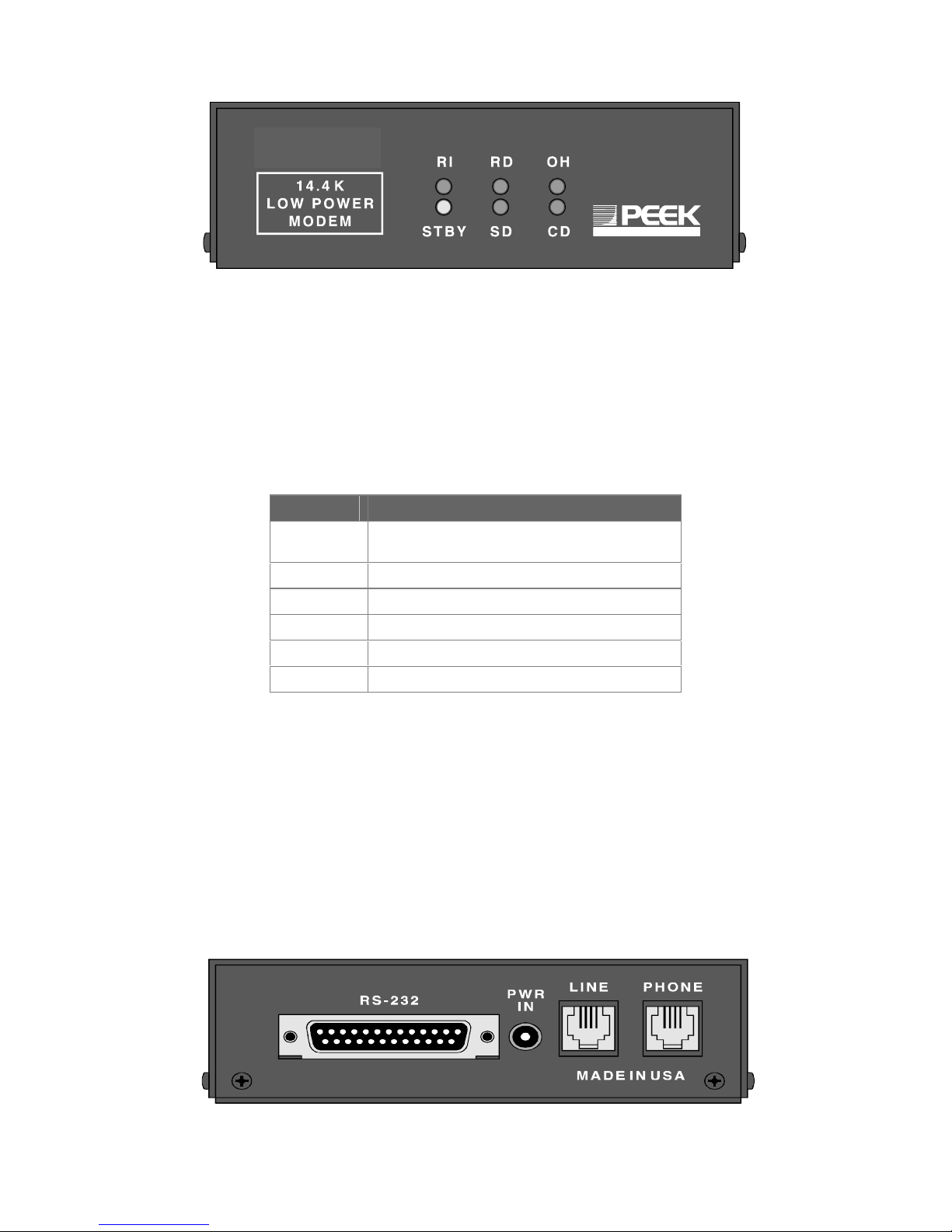
The front panel of the LPM-14-E features six LED indicators as shown in Figure 1.1. The STBY
lamp indicates whether the LPM-14-E is in the standby mode or the active mode. When the LPM-14-E is
first powered up, the LPM-14-E enters into the standby mode and flashes the STBY lamp. All other
indicators should be off when the unit is in the standby mode. When the LPM-14-E detects the ringing
voltage or an activity on the RS-232 RD line, it goes into the full power mode and the STBY lamp will go
off. The rest of the lamps are used to indicate various stages during a connecting session with a remote
modem. Table 1.1 lists the indicators and their functions.
Figure 1.1
TABLE 1.1
INDICATORS FUNCTIONS
STBY In standby mode when flashing; active mode
otherwise
RI Ringing voltage detected
OH Off Hook
CD Carrier signal detected
RD Receiving data from DTE
SD Sending data to the DTE
1.4 INSTALLATION
As with standard modem equipment, the LPM-14-E comes with the required connections on the
back panel to allow it to be connected to any Data Terminal Equipment (DTE). Figure 1.2 shows the
connectors and their functions. An RS-232C cable from the DTE equipment connects to the RS-232 port
as shown. DC supply ranging from 5.5V to 40V can be wired to the supplied power plug with the negative
terminal on the outside shell and the positive terminal connected to the inner recepticle as shown in the
figure. This plug then connects to the power jack on the LPM-14-E. Optionally, the power plug from the
Peek supplied wall mount AC transformer can be connected to the power jack on the LPM-14-E. A Dial-up
line from the local phone company connects to the RJ-11 connector marked “Line,” and a telephone,
which is to be shared with the LPM-14-E on the same dial-up line, can be connected to the RJ-11
connector marked “Phone.”
Figure 1.2
2
Page 7

1.5 MODEM CONTROL
The LPM-14-E communicates with the DTE through the RS-232 connection and can be controlled
by command strings received from the DTE. The command strings are in the form of AT commands.
The string is always preceded by the letters “AT” and ends with the Carriage Return character. The LPM14-E uses the “AT” part of the string to sense the different baud rates and line settings that the DTE might
be set at. Section 2 of this manual lists the summary of the AT commands available for the LPM-14-E.
While in the active mode, the LPM-14-E can be in one of its two operating modes—command
mode and data mode. “AT” commands are accepted only when the modem is in the command mode.
The DTE can set various operating parameters that are part of the modem’s profiles while the LPM-14-E
is in the command mode. Also, the DTE can instruct the LPM-14-E to dial a phone number, answer an
incoming call, show the current modem profile, etc. The LPM-14-E can be instructed to enter the data
mode by the Dial, Answer or Online commands. Section 3 will discuss these commands in more detail.
For example, after receiving the “ATD555-1212” command, it dials the phone number and attempts to
connect with the modem at that number. When the remote modem answers and the carrier signal has
been detected, the LPM-14-E goes into the data mode.
In the data mode, the LPM-14-E will send all received data from the remote modem to the DTE.
At the same time, all characters received from the DTE will be transmitted to the remote modem.
Depending on the setting of parameters in the active modem profile, data to be transmitted may be
compressed and/or formatted for automatic error correction. Data received from the DTE will first be
formatted by either MNP 4 or V.42 algorithm for automatic error correction by the remote modem, then
they are compressed by either the MNP 5 or V.42bis algorithm for improved data transmission efficiency.
Data from the remote modem will first be uncompressed by the respective compression protocol—MNP 5
or V.42bis. The LPM-14-E recognizes the type of compression protocol used by inspecting the patterns in
the data. It then tests the data for any transmission errors and applies automatic error correction
procedures to ensure that all remotely received data is accurate. Data to be transmitted are processed in
the manner described above, except the Escape sequence.
An Escape sequence is composed of an Escape character repeated three times, followed by a
brief pause. The Escape character is usually the ‘+’ sign but may be modified to any symbol by one of the
AT commands. Once the Escape sequence is received, the LPM-14-E enters the command mode,
waiting for an AT command. At this time, the LPM-14-E can be instructed to re-enter the data mode by
the online command (“ATO”) or to disconnect from the remote modem by the “ATH” command. When
disconnected from the remote modem, the LPM-14-E will be in the command mode, waiting for a
command. If no command is received within 25 seconds, the LPM-14-E will switch to the standby mode
to conserve power.
3
Page 8

2. AT COMMAND SUMMARY
2.1. BASIC AT COMMANDS
Command Function
A/ Re-execute command.
A Go off-hook and attempt to answer a call.
B0 Select V.22 connection at 1200 bps.
B1 Select Bell 212A connection at 1200 bps.
C1 Return OK message.
Dn Dial modifier.
E0 Turn off command echo.
E1 Turn on command echo.
F0 Select auto-detect mode (equivalent to N1).
F1 Select V.21 or Bell 103.
F2 Reserved.
F3 Select V.23 line modulation.
F4 Select V.22 or Bell 212A 1200 bps line speed.
F5 Select V.22 bis line modulation.
F6 Select V.32 bis or V.32 4800 line modulation.
F7 Select V.32 bis 7200 line modulation.
F8 Select V.32 bis or V.32 9600 line modulation.
F9 Select V.32 bis 12000 line modulation.
F10 Select V.32 bis 14400 line modulation.
H0 Initiate a hang-up sequence.
H1 If on-hook, go off-hook and enter command mode.
I0 Report product code.
I1 Report pre-computed checksum.
I2 Report OK.
I3 Report firmware revision, model, and interface type.
I4 Report response programmed by an OEM.
I5 Report the country code parameter.
I6 Report modem data pump model and code revision.
I7 Reports the DAA code (W-class models only).
L0 Set low speaker volume.
L1 Set low speaker volume.
L2 Set medium speaker volume.
L3 Set high speaker volume.
M0 Turn speaker off.
M1 Turn speaker on during handshaking and turn speaker off while receiving carrier.
M2 Turn speaker on during handshaking and while receiving carrier.
M3 Turn speaker off during dialing and receiving carrier and turn speaker on during answering.
N0 Turn off automode detection.
N1 Turn on automode detection.
O0 Go on-line.
O1 Go on-line and initiate a retrain sequence.
P Force pulse dialing.
Q0 Allow result codes to DTE.
Q1 Inhibit result codes to DTE.
Sn Select S-Register as default.
Sn? Return the value of S-Register n.
=v Set default S-Register to value v.
? Return the value of default S-Register.
T Force DTMF dialing.
V0 Report short form (terse) result codes.
V1 Report long form (verbose) result codes.
W0 Report DTE speed in EC mode.
W1 Report line speed, EC protocol and DTE speed.
W2 Report DCE speed in EC mode.
4
Page 9

X0 Report basic call progress result codes, i.e., OK, CONNECT, RING, NO CARRIER, NO ANSWER
and ERROR.
X1 Report basic call progress result codes and connections speeds, i.e., OK, CONNECT, RING, NO
CARRIER, NO ANSWER, CONNECT XXXX, and ERROR.
X2 Report basic call progress result codes and connections speeds, i.e., OK, CONNECT, RING, NO
CARRIER, NO ANSWER, CONNECT XXXX, and ERROR.
X3 Report basic call progress result codes and connection rate, i.e., OK, CONNECT, RING, NO
CARRIER, NO ANSWER, CONNECT XXXX, BUSY, and ERROR.
X4 Report all call progress result codes and connection rate, i.e., OK, CONNECT, RING, NO
CARRIER, NO ANSWER, CONNECT XXXX, BUSY, NO DIAL TONE and ERROR.
Y0 Disable long space disconnect before on-hook.
Y1 Enable long space disconnect before on-hook.
Z0 Restore stored profile 0 after warm reset.
Z1 Restore stored profile 1 after warm reset.
&C0 Force RLSD active regardless of the carrier state.
&C1 Allow RLSD to follow the carrier state.
&D0 Interpret DTR ON-to-OFF transition per &Qn:
&Q0, &Q5, &Q6 The modem ignores DTR.
&Q1, &Q4 The modem hangs up.
&Q2, &Q3 The modem hangs up.
&D1 Interpret DTR ON-to-OFF transition per &Qn:
&Q0, &Q1, &Q4,.
&Q5, &Q6 Asynchronous escape.
&Q2, &Q3 The modem hangs up.
&D2 Interpret DTR ON-to-OFF transition per &Qn:
&Q0 through &Q6 The modem hangs up.
&D3 Interpret DTR ON-to-OFF transition per &Qn:.
&Q0, &Q1, &Q4,.
&Q5, &Q6 The modem performs soft reset.
&Q2, &Q3 The modem hangs up.
&F0 Restore factory configuration 0.
&F1 Restore factory configuration 1.
&G0 Disable guard tone.
&G1 Disable guard tone.
&G2 Enable 1800 Hz guard tone.
&J0 Set S-Register response only for compatibility.
&J1 Set S-Register response only for compatibility.
&K0 Disable DTE/DCE flow control.
&K3 Enable RTS/CTS DTE/DCE flow control.
&K4 Enable XON/XOFF DTE/DCE flow control.
&K5 Enable transparent XON/XOFF flow control.
&K6 Enable both RTS/CTS and XON/XOFF flow control.
&L0 Select dial up line operation.
&L1 Select leased line operation.
&M0 Select direct asynchronous mode.
&M1 Select sync connect with async off-line command mode. *
&M2 Select sync connect with async off-line command mode and enable DTR dialing of directory zero. *
&M3 Select sync connect with async off-line command mode and enable DTR to act as Talk/Data
switch. *
&P0 Set 10 pps pulse dial with 39%/61% make/break.
&P1 Set 10 pps pulse dial with 33%/67% make/break.
&P2 Set 20 pps pulse dial with 39%/61% make/break.
&P3 Set 20 pps pulse dial with 33%/67% make/break.
&Q0 Select direct asynchronous mode.
&Q1 Select sync connect with async off-line command mode.
&Q2 Select sync connect with async off-line command mode; enable DTR dialing of directory zero.
&Q3 Select sync connect with async off-line command mode; enable DTR to act as Talk/Data switch.
&Q4 Select Hayes AutoSync mode.
&Q5 Modem negotiates an error corrected link.
&Q6 Select asynchronous operation in normal mode.
&R0 CTS tracks RTS (async) or acts per V.25 (sync).
&R1 CTS is always active.
&S0 DSR is always active.
&S1 DSR acts per V.25.
5
Page 10

&T0 Terminate any test in progress.
&T1 Initiate local analog loopback.
&T2 Returns ERROR result code.
&T3 Initiate local digital loopback.
&T4 Allow remote digital loopback.
&T5 Disallow remote digital loopback request.
&T6 Request an RDL without self-test.
&T7 Request an RDL with self-test.
&T8 Initiate local analog loop with self-test.
&V Display current configurations.
&W0 Store the active profile in NVRAM profile 0.
&W1 Store the active profile in NVRAM profile 1.
&X0 Select internal timing for the transmit clock.
&X1 Select external timing for the transmit clock.
&X2 Select slave receive timing for the transmit clock.
&Y0 Recall stored profile 0 upon power up.
&Y1 Recall stored profile 1 upon power up.
&Zn=x Store dial string x (to 35) to location n (0 to 3 depending upon modem model).
%E0 Disable line quality monitor and auto retrain.
%E1 Enable line quality monitor and auto retrain.
%E2 Enable line quality monitor and fallback/fall forward.
%L Return received line signal level.
%Q Report the line signal quality.
\G0 Disable modem to modem flow control.
\G1 Enable modem to modem flow control.
\Kn Controls break handling during three states:
When modem receives a break from the DTE:
\K0,2,4 Enter on-line command mode, no break sent to the remote modem.
\K1 Clear buffers and send break to remote modem.
\K3 Send break to remote modem immediately.
\K5 Send break to remote modem in sequence with transmitted data.
When modem receives \B in on-line command state:
\K0,1 Clear buffers and send break to remote modem.
\K2,3 Send break to remote modem immediately.
\K4,5 Send break to remote modem in sequence with transmitted data.
When modem receives break from the remote modem:
\K0,1 Clear data buffers and send break to DTE.
\K2,3 Send a break immediately to DTE.
\K4,5 Send a break with received data to the DTE.
\N0 Select normal speed buffered mode.
\N1 Select direct mode.
\N2 Select reliable link mode.
\N3 Select auto reliable mode.
\N4 Force LAPM mode.
\N5 Force MNP mode.
2.2. ECC COMMANDS
%C0 Disable data compression.
%C1 Enable MNP 5 data compression.
%C2 Enable V.42 bis data compression.
%C3 Enable both V.42 bis and MNP 5 compression.
\A0 Set maximum block size in MNP to 64.
\A1 Set maximum block size in MNP to 128.
\A2 Set maximum block size in MNP to 192.
\A3 Set maximum block size in MNP to 256.
\Bn Send break of n x 100 ms.
6
Page 11

2.3. MNP 10 COMMANDS
)M0 Disable MNP 10 link negotiation power adjustment.
)M1 Enable MNP 10 link negotiation power adjustment.
)M2 Enable cellular mode without power level adjustment during MNP 10 link negotiation.
*H0 Select MNP 10 link negotiation at highest rate.
*H1 Select MNP 10 link negotiation at 1200 bps.
*H2 Select MNP 10 link negotiation at 4800 bps.
-K0 Disable MNP 10 extended services.
-K1 Enable MNP 10 extended services.
-K2 Enable MNP 10 extended services detection only.
-Q0 Disable MNP 10 fallback to 2400 bps (V.22 bis)/1200 bps (V.22).
-Q1 Enable MNP 10 fallback to 2400 bps (V.22 bis)/1200 bps (V.22).
@M0 Select initial transmit level of -26 dBm.
@M1 Select initial transmit level of -30 dBm.
@M2 Select initial transmit level of -10 dBm.
@M3 - @M10 Select initial transmit level of -10 dBm.
@M11 Select initial transmit level of -11 dBm.
@M12 Select initial transmit level of -12 dBm.
.
.
.
@M30 Select initial transmit level of -30 dBm.
@M31 Select initial transmit level of -31 dBm.
:E0 Disable the compromise equalizer.
:E1 Enable the compromise equalizer.
2.4. FAX CLASS 1
+FCLASS=n Service class.
+FAE=n Data/fax auto answer
+FRH=n Receive data with HDLC framing.
+FRM=n Receive data.
+FRS=n Receive silence.
+FTH=n Transmit data with HDLC framing.
+FTM=n Transmit data.
+FTS=n Stop transmission and wait.
7
Page 12

3. AT COMMAND SET
3.1. AT COMMAND GUIDELINES
The basic AT commands used to control modem operation are defined in this section. These commands are summarized in
section 2. The default values are typical of a fully configured modem supporting all data rates and options.
3.1.1. AT Commands, DTE Adaption
Under AT operation, the serial interfaced modem performs an autobaud/autoparity/autolength function on each AT header entered. The
autolength/autoparity facility can detect 7- or 8-bit characters of even, odd, or no parity with one stop bit.
3.1.2. AT Command Format
A command line is a string of characters sent from a DTE to the modem (DCE) while the modem is in a command mode. A command line
has a prefix, a body, and a terminator. Each command line (with the exception of the A/ command) must begin with the character sequence
AT and must be terminated by a carriage return. Commands entered in upper case or lower case are accepted, but both the A and T must be
of the same case, i.e., “AT” = ASCII 065, 084 or “at” = ASCII 097, 116. The body is a string of commands restricted to printable ASCII
characters (032 - 126). Space characters (ASCII 032) and control characters other than CR (ASCII 013) and BS (ASCII 010) in the command
string are ignored. The default terminator is the ASCII <CR> character. Characters that precede the AT prefix are ignored. The command line
interpretation begins upon receipt of the carriage return character.Characters within the command line are parsed as commands with
associated parameter values. The basic commands consist of single ASCII characters, or single characters preceded by a prefix character
(e.g., “&”), followed by a decimal parameter. Missing decimal parameters are evaluated as 0. The modem supports the editing of command
lines by recognizing a backspace character. When modem echo is enabled, the modem responds to receipt of a backspace or delete by
echoing a backspace character, a space character, and another backspace. The hex value to be used for the backspace character is
programmable through register S5. Values equal to 0 or greater than 127, or the value which corresponds to the carriage return character,
cannot be used for the backspace character. This editing is not applicable to the AT header of a command. A command line may be aborted
at any time by entering < cntrl-x > (18h).The AT sequence may be followed by any number of commands in sequence, except for commands
such as Z, D, or A. Commands following commands Z, D, or A on the same command line will be ignored. The maximum number of
characters on any command line is 39 (including “A” and “T”). If a syntax error is found anywhere in a command line command, the remainder
of the line will be ignored and the ERROR result code will be returned.Most commands entered with parameters out of range will not be
accepted and the ERROR response will be returned to the DTE.Commands will only be accepted by the modem once the previous command
has been fully executed, which is normally indicated by the return of an appropriate result code. Execution of commands D and A, either as a
result of a direct command or a re-execute command, will be aborted if another character is entered before completion of the handshake.
3.1.3. Escape Code Sequence
When the modem has established a connection and has entered on-line data mode, it is possible to break into the data transmission in order
to issue further commands to the modem in an on-line command mode. This is achieved by the DTE sending to the modem a sequence of
three ASCII characters specified by register S2. The default character is ‘+’. The timing of the three characters must comply with specific time
constraints. There is a guard time before the first character (the pre-sequence time), a guard time following the third character (the postsequence time), and a guard time-out between the first and second characters and between the second and third characters (the intercharacter time). These times are controlled by the value recorded in register S12.
3-1
Page 13

3.2. AT COMMAND SET
The modem will respond to the commands detailed below. Parameters applicable to each command are listed with the command description.
The defaults shown for each configuration command are those used in the factory profile.
3.2.1. AT Commands
A/ - Re-execute Command
The modem behaves as though the last command line had been re-sent by the DTE. “A/” will repeat all the commands in the command
buffer.The principal application of this command is to place another call (using the Dial command) that failed to connect due to a busy line, no
answer, or a wrong number. This command must appear alone on a command line. This command should not be terminated by a carriage
return.
AT= x - Write to Selected S-Register
This command writes the value x to the currently selected S-Register. An S-Register can be selected by using the ATSn command. All of the
S-Registers will return the OK response if x is a number.
Result Codes:
OK For all arguments.
AT? - Read Selected S-Register
This command reads and displays the selected S-Register. An S-Register can be selected by using the ATSn command.
Result Codes:
OK For all arguments.
A - Answer
The modem will go off-hook and attempt to answer an incoming call if correct conditions are met. Upon successful completion of answer
handshake, the modem will go on-line in answer mode. If +FCLASS=0 is selected, the modem will enter the connect state after exchanging
carrier with the remote modem. If no carrier is detected within a period specified in register S7, the modem hangs up. Any character entered
during the connect sequence will abort the connection attempt.If +FCLASS=1 or 2 is selected to prepare the modem to answer a Fax call, the
modem will go off-hook in V.21 answer mode. It will generate the V.21 2100 Hz answer tone for 3 ± 0.5 seconds and, following a delay of 70
ms, will proceed as if the +FTH=3 command were issued. At any stage up to (but excluding) the +FTH=3 command state, any character will
abort the communication. (See the description of the +FTH command for details.)
Bn - CCITT or Bell
When the modem is configured to allow either option, the modem will select Bell or CCITT modulation for a line speed connection of 300 or
1200 bps according to the parameter supplied. Any other line speed will use a CCITT modulation standard. The parameter value, if valid, is
written to S27 bit 6. (Also, see ATFn command.
B0 Selects CCITT operation at 300 or 1200 bps during Call Establishment and a subsequent connection.
B1 Selects BELL operation at 300 or 1200 bps during Call Establishment and a subsequent connection. (Default)
Result Codes:
OK n = 0 or 1.
ERROR Otherwise.
Cn - Carrier Control
This command is included for compatibility only, and has no effect other than returning a result code. The only valid parameter is 1.Result
OK n = 1.
ERROR Otherwise.
Codes:
3-2
Page 14

Dn - Dial
This command directs the modem to go on-line, dial according to the string entered and attempt to establish a connection. If no dial string is
supplied, the modem will go on-line and attempt the handshake in originate mode. If +FCLASS=0 is selected, the modem will behave as a
data modem and will attempt to connect to another data modem. The modem will have up to the period of time specified by register S6 or S7
to wait for carrier and complete the handshake. If this time expires before the modem can complete the handshake, the modem will go onhook with the NO CARRIER response. This command will be aborted in progress upon receipt of any DTE character before completion of the
handshake.If +FCLASS=1 or 2 is selected, the modem will behave as a facsimile modem and attempt to connect to a facsimile machine (or
modem) by entering the HDLC V.21 channel 2 receive state (as if +FRH=3 had been issued). This command will be aborted upon receipt of
any DTE character if the modem has not finished dialing. In this case, the modem will go on-hook and return to command mode after
displaying the NO CARRIER message. If the modem has finished dialing, it proceeds as if the +FRH=3 command has been issued. (Refer to
the +FRH command to determine how the modem behaves following this stage).
Dial Modifiers. The valid dial string parameters are described below. Punctuation characters may be used for clarity, with parentheses,
hyphen, and spaces being ignored.
0-9 DTMF digits 0 to 9.
• The ‘star’ digit (tone dialing only).
# The ‘gate’ digit (tone dialing only).
A-D DTMF digits A, B, C, and D.
L Re-dial last number: the modem will re-dial the last valid telephone number. The L must be immediately after the
D with all the following characters ignored.
P Select pulse dialing: pulse dial the numbers that follow until a “T” is encountered. Affects current and subsequent
dialing.
T Select tone dialing: tone dial the numbers that follow until a “P” is encountered. Affects current and subsequent
dialing
S=n Dial the number stored in the directory (n = 0 to 3). (See &Z.)
! Flash: the modem will go on-hook for a time defined by the value of S29.
W Wait for dial tone: the modem will wait for dial tone before dialing the digits following “W”. If dial tone is not
detected within the time specified by S7, the modem will abort the rest of the sequence, return on-hook, and
generate an error message.
@ Wait for silence: the modem will wait for at least 5 seconds of silence in the call progress frequency band before
continuing with the next dial string parameter. If the modem does not detect these 5 seconds of silence before the
expiration of the call abort timer (S7), the modem will terminate the call attempt with a NO ANSWER message. If
busy detection is enabled, the modem may terminate the call with the BUSY result code. If answer tone arrives
during execution of this parameter, the modem handshakes.
& Wait for credit card dialing tone before continuing with the dial string. If bong is not detected within the time
specified by S7, the modem will abort the rest of the sequence, return on-hook, and generate an error message.
, Dial pause: the modem will pause for a time specified by S8 before dialing the digits following “,”.
; Return to command state. Added to the end of a dial string, this causes the modem to return to the command
state after it processes the portion of the dial string preceding the “;”. This allows the user to issue additional AT
commands while remaining off-hook. The additional AT commands may be placed in the original command line
following the “;” and/or may be entered on subsequent command lines. The modem will enter call progress only
after an additional dial command is issued without the “;” terminator. Use “H” to abort the dial in progress, and go
back on-hook.
^ Toggles calling tone enable/disable: applicable to current dial attempt only.
( ) Ignored: may be used to format the dial string.
• Ignored: may be used to format the dial string.
<space> Ignored: may be used to format the dial string.
<i> Invalid character: will be ignored.
3-3
Page 15

En - Command Echo
The modem enables or disables the echo of characters to the DTE according to the parameter supplied. The parameter value, if valid, is
written to S14 bit 1.
E0 Disables command echo.
E1 Enables command echo. (Default.)
Result Codes:
OK n = 0 or 1.
ERROR Otherwise.
Fn - Select Line Modulation
This command selects the line modulation according to the parameter supplied. The line modulation is fixed unless Automode is selected.
This command interacts with the S37 and the N command. The parameter value, if valid, is written to S37 bits 0-4. To select line modulation,
it is recommended that either the F command, or a combination of the S37 and the N command, be used, but not both.
F0 Selects auto-detect mode. Sets N1 and sets S31 bit 1. In this mode, the modem configures for Automode
operation. All connect speeds supported by the modem are possible according to the remote modem’s
preference. The contents of S37 are ignored as is the sensed DTE speed.
F1 Selects V.21 or Bell 103 according to the B setting as the only acceptable line speed resulting in a subsequent
connection. Sets N0, sets S37 to 1, and clears S31 bit 1. This command is equivalent to the command string:
ATN0S37=1.
F2 Not supported.
F3 Selects V.23 as the only acceptable line modulation for a subsequent connection. Originator is at 75 bps and
answerer is at 1200 bps. Sets N0, sets S37 to 7, and clears S31 bit 1. This command is equivalent to the
command string: ATN0S37=7.
F4 Selects V.22 1200 or Bell 212A according to the B command setting as the only acceptable line speed for a
subsequent connection. Sets N0, sets S37 to 5, and clears S31 bit 1. This command is equivalent to the
command string: ATN0S37=5.
F5 Selects V.22 bis as the only acceptable line modulation for a subsequent connection. Sets N0, sets S37 to 6,
and clears S31 bit 1. This command is equivalent to the command string: ATN0S37=6.
F6 Select V.32 bis 4800 or V.32 4800 as the only acceptable line modulation for a subsequent connection. Sets
N0, sets S37 to 8, and clears S31 bit 1. This command is equivalent to the command string: ATN0S37=8.
F7 Selects V.32 bis 7200 as the only acceptable line modulation for a subsequent connection. Sets N0, sets S37
to 12, and clears S31 bit 1. This command is equivalent to the command string: ATN0S37=12.
F8 Selects V.32 bis 9600 or V.32 9600 as the only acceptable line modulations for a subsequent connection. Sets
N0, sets S37 to 9, and clears S31 bit 1. This command is equivalent to the command string: ATN0S37=9.
F9 Selects V.32 bis 12000 as the only acceptable line modulation for a subsequent connection. Sets N0, sets S37
to 10, and clears S31 bit 1. This command is equivalent to the command string: ATN0S37=10.
F10 Selects V.32 bis 14400 as the only acceptable line modulation for a subsequent connection. Sets N0, sets S37
to 11, and clears S31 bit 1. This command is equivalent to the command string: ATN0S37=11.
Hn - Disconnect (Hang-Up)
This command initiates a hang up sequence.
H0 The modem will release the line if the modem is currently on-line, and will terminate any test (AT&T) that is in
progress. Modulation specific, and error correction protocol specific (S38) processing is handled outside of the
H0 command.
H1 If on-hook, the modem will go off-hook and enter command mode.
Result Codes:
OK n = 0 or 1.
ERROR Otherwise.
3-4
Page 16

In - Identification
The modem reports to the DTE the requested result according to the command parameter.
I0 Reports product code (e.g., “14400”).
I1 Reports a precomputed checksum (see firmware release notes).
I2 Reports “OK”.
I3 Reports firmware revision (VX.XXX)-model code (A = 64K US, C = 128K US, D = 128K W-Class, E = 64K W-
Class), interface type (S = serial; P = parallel), and MCU model (29 = C29; 39 = C39) (e.g., “V1.297-CS29”).
I4 Reports OEM defined identifier string (e.g., “RC96ACL”) in either Hayes-compatible binary format.
I5 Reports Country Code parameter (e.g., “022”).
I6 Reports modem data pump model and internal code revision (e.g., RC144DPL Rev CE).
I7 Reports the DAA code. (e.g., 000 for US or Canada)
Result Codes:
OK n = 0 to 7.
ERROR Otherwise.
Ln - Speaker Volume
The modem sets the speaker volume control according to the parameter supplied. The parameter value, if valid, is written to S22 bits 0 and 1.
L0 Low volume.
L1 Low volume. (Default.)
L2 Medium volume.
L3 High volume.
Result Codes:
OK n = 0 to 3.
ERROR Otherwise.
Mn - Speaker Control
This command selects when the speaker will be on or off. The parameter value, if valid, is written to S22 bits 2 and 3.
M0 Speaker is always off.
M1 Speaker is on during call establishment, but off when receiving carrier. (Default.)
M2 Speaker is always on.
M3 Speaker is off when receiving carrier and during dialing, but on during answering.
Result Codes:
OK n = 0 to 3.
ERROR Otherwise.
Nn - Automode Enable
This command enables or disables Automode detection. The parameter value, if valid, is written to S31 bit 1.
N0 Automode detection is disabled. A subsequent handshake will be conducted according to the contents of S37
or, if S37 is zero, according to the most recently sensed DTE speed.
N1 Automode detection is enabled. A subsequent handshake will be conducted according to the Automode
algorithm supported by the modem. This command is equivalent to F0. (Default.)
Result Codes:
OK n = 0 or 1.
ERROR Otherwise.
On - Return to On-Line Data Mode
This command determines how the modem will enter the on-line data mode. If the modem is in the on-line command mode, the enters the
on-line data mode with or without a retrain. If the modem is in the off-line command mode (no connection), ERROR is reported.
O0 Enters on-line data mode without a retrain. Handling is determined by the Call Establishment task. Generally, if
a connection exists, this command connects the DTE back to the remote modem after an escape (+++).
O1 Enters on-line data mode with a retrain before returning to on-line data mode.
Result Codes:
OK n = 0 or 1 and a connection exists.
ERROR Otherwise or if not connected.
3-5
Page 17

P - Set Pulse Dial Default
This command forces pulse dialing until the next T dial modifier or T command is received. Sets S14 bit 5. As soon as a dial command is
executed which explicitly specifies the dialing mode for that particular call (e.g., ATDT...), this command is overridden so that all future dialing
will be tone dialed. (See T command).
Result Code:
OK
Qn - Quiet Results Codes Control
The command enables or disables the sending of result codes to the DTE according to the parameter supplied. The parameter value, if valid,
is written to S14 bit 2.
Q0 Enables result codes to the DTE. (Default.)
Q1 Disables result codes to the DTE.
Result Codes:
OK n = 0 or 1.
ERROR Otherwise.
Sn - Read/Write S-Register
The modem selects an S-Register, performs an S-Register read or write function, or reports the value of an S-Register.
n Establishes S-Register n as the last register accessed.
n=v Sets S-Register n to the value v.
n? Reports the value of S-Register n.
The parameter n can be omitted, in which case the last S-Register accessed will be assumed. The S can be omitted for AT= and AT?, in
which case the last S-Register accessed will be assumed.
For example:
ATS7 establishes S7 as the last accessed register.
AT=40 sets the contents of the last register accessed to 40.
ATS=20 sets the contents of the last register accessed to 20.
If the number “n” is beyond the range of the S-Registers available, the modem will return the ERROR message. The value “v” is “MOD”ed
with 256. If the result is outside the range permitted for a given S-Register the values will still be stored, but functionally the lower and higher
limits will be observed. Input and output are always in decimal format. Note that some S-Registers are read-only.In some cases, writing to the
S-Register will appear to be accepted but the value will not actually be written.
T - Set Tone Dial Default
This command forces DTMF dialing until the next P dial modifier or P command is received. The modem will set an S-Register bit to indicate
that all subsequent dialing should be conducted in tone mode. Note that the DP command will override this command. Clears S14 bit 5. (See
P.)
Result Code:
OK
Vn - Result Code Form
This command selects the sending of short-form or long-form result codes to the DTE. The parameter, if valid, is written to S14 bit 3.
V0 Enables short-form (terse) result codes. Line feed is not issued before a short-form result code.
V1 Enables long-form (verbose) result codes. (Default.)
Result Codes:
OK n = 0 or 1.
ERROR Otherwise.
3-6
Page 18

Wn - Connect Message Control
This command controls the format of CONNECT messages. The parameter value, if valid, is written to S31 bits 2 and 3. Note that the Wn
command can be overridden by register S95 bits (see S95 description).
W0 Upon connection, the modem reports only the DTE speed (e.g., CONNECT 19200). Subsequent responses are
disabled. (Default.)
W1 Upon connection, the modem reports the line speed, the error correction protocol, and the DTE speed,
respectively. Subsequent responses are disabled.
W2 Upon connection, the modem reports the DCE speed (e.g., CONNECT 14400). Subsequent responses are
disabled.
Result Codes:
OK n = 0, 1, or 2.
ERROR Otherwise.
Xn - Extended Result Codes:
This command selects which subset of the result messages will be used by the modem to inform the DTE of the results of commands.Blind
dialing is enabled or disabled by country parameters. If the user wishes to enforce dial tone detection, a “W” can be placed in the dial string
(see D command). Note that the information below is based upon the default implementation of the X results table. Table 3-1 indicates the
messages which are enabled for each X value.If the modem is in facsimile mode (+FCLASS=1 or 2), the only message sent to indicate a
connection is CONNECT without a speed indication.
X0 Disables monitoring of busy tones; send only OK, CONNECT, RING, NO CARRIER, ERROR, and NO
ANSWER result codes. The value 000b is written to S22 bits 6, 5, and 4, respectively.
X1 Disables monitoring of busy tones; send only OK, CONNECT, RING, NO CARRIER, ERROR, NO ANSWER,
and CONNECT XXXX (XXXX = rate). The value 100b is written to S22 bits 6, 5, and 4, respectively.
X2 Disables monitoring of busy tones; send only OK, CONNECT, RING, NO CARRIER, ERROR, NO DIALTONE,
NO ANSWER, and CONNECT XXXX. The value 101b is written to S22 bits 6, 5, and 4, respectively.
X3 Enables monitoring of busy tones; send only OK, CONNECT, RING, NO CARRIER, ERROR, NO ANSWER,
and CONNECT XXXX. The value 110b is written to S22 bits 6, 5, and 4, respectively.
X4 Enables monitoring of busy tones; send all messages. The value 111b is written to S22 bits 6, 5, and 4,
respectively. (Default.)
Result Codes:
OK n = 0 to 4.
ERROR Otherwise.
3-7
Page 19

Table 3-1. Result Codes
Short Form Long Form n Value in ATXn Command
0 1 2 3 4
0 OK x x x x x
1 CONNECT x x x x x
2 RING x x x x x
3 NO CARRIER x x x x x
4 ERROR x x x x x
5 CONNECT 1200 1 x x x x
6 NO DIALTONE 3 3 x x x
7 BUSY 3 3 3 x x
8 NO ANSWER x x x x x
9 CONNECT 0600 1 x x x x
10 CONNECT 2400 1 x x x x
11 CONNECT 4800 1 x x x x
12 CONNECT 9600 1 x x x x
13 CONNECT 7200 1 x x x x
14 CONNECT 12000 1 x x x x
15 CONNECT 14400 1 x x x x
16 CONNECT 19200 1 x x x x
17 CONNECT 38400 1 x x x x
18 CONNECT 57600 1 x x x x
22 CONNECT 75TX/1200RX 1 x x x x
23 CONNECT 1200TX/75RX 1 x x x x
24 DELAYED 4 4 4 4 x
32 BLACKLISTED 4 4 4 4 x
33 FAX x x x x x
35 DATA x x x x x
40 CARRIER 300 x x x x x
44 CARRIER 1200/75 x x x x x
45 CARRIER 75/1200 x x x x x
46 CARRIER 1200 x x x x x
47 CARRIER 2400 x x x x x
48 CARRIER 4800 x x x x x
49 CARRIER 7200 x x x x x
50 CARRIER 9600 x x x x x
51 CARRIER 12000 x x x x x
52 CARRIER 14400 x x x x x
66 COMPRESSION: CLASS 5 x x x x x
67 COMPRESSION: V.42 bis x x x x x
69 COMPRESSION: NONE x x x x x
76 PROTOCOL: NONE x x x x x
77 PROTOCOL: LAPM x x x x x
80 PROTOCOL: ALT x x x x x
81 PROTOCOL: ALT-CELLULAR x x x x x
+F4 +FCERROR x x x x x
Note: An ‘x’ in a column indicates that the message (either the long form if verbose, or the value only for
short form) will be generated when that particular value of ‘n’ (shown at the top of the column) has been
selected by the use of ATXn. If the column is blank, then no message will be generated for that X option.
A numeral indicates which less explicit message (verbose or short form) will be output for that X option.
(Also, see Section 3.3).
Yn - Long Space Disconnect
This command enables/disables the generation and response to long space disconnect. The parameter value, if valid, is written to S21 bit 7.
Y0 Disables long space disconnect. (default.)
Y1 Enables long space disconnect. In non-error correction mode, the modem will send a long space of four
seconds prior to going on-hook. In error correction mode, the modem will respond to the receipt of a long space
(i.e., a break signal greater than 1.6 seconds) by going on-hook.
Result Codes:
OK n = 0 or 1.
ERROR Otherwise.
3-8
Page 20

Zn - Soft Reset and Restore Profile
The modem performs a soft reset and restores the configuration profile according to the parameter supplied. If no parameter is specified,
zero is assumed.
Z0 Soft reset and restore stored profile 0.
Z1 Soft reset and restore stored profile 1.
Result Codes:
OK n = 0 or 1.
ERROR Otherwise.
3.2.2. AT& Commands
&Cn - RLSD (DCD) Option
The modem controls the RLSD output in accordance with the parameter supplied. The parameter value, if valid, is written to S21 bit 5.
&C0 RLSD remains ON at all times. (Default.)
&C1 RLSD follows the state of the carrier.
Result Codes:
OK n = 0 or 1.
ERROR Otherwise.
&Dn - DTR Option
This command interprets the ON to OFF transition of the DTR signal from the DTE in accordance with the parameter supplied. The parameter
value, if valid, is written to S21 bits 3 and 4.
&D0 - DTR drop is interpreted according to the current &Q setting as follows: (Default.)
&Q0,&Q5,&Q6 DTR is ignored. Allows operation with DTEs which do not provide DTR.
&Q1,&Q4 DTR drop causes the modem to hang up. Auto-answer is not affected.
&Q2,&Q3 DTR drop causes the modem to hang up. Auto-answer is inhibited.
&D1 DTR drop is interpreted according to the current &Qn setting as follows:
&Q0,&Q1,&Q4,&Q5,&Q6 DTR drop is interpreted by the modem as if the asynchronous escape sequence
&Q2,&Q3 DTR drop causes the modem to hang up. Auto-answer is inhibited.
&D2 DTR drop is interpreted according to the current &Qn setting as follows:
&Q0 through &Q6 DTR drop causes the modem to hang up. Auto-answer is inhibited.
&D3 DTR drop is interpreted according to the current &Qn setting as follows:
&Q0,&Q1,&Q4,&Q5,&Q6 DTR drop causes the modem to perform a soft reset as if the Z command were
&Q2, &Q3 DTR drop causes the modem to hang up. Auto-answer is inhibited.
If &Q5, &Q6, +FCLASS=1 or +FCLASS=2 is in effect, the action taken is the same as for &Q0.
had been entered. The modem returns to asynchronous command state without
disconnecting.
received. The &Y setting determines which profile is loaded.
&Fn - Restore Factory Configuration (Profile)
The modem loads the factory default configuration (profile). The factory defaults are identified for each command and in the S-Register
descriptions. A configuration (profile) consists of a subset of S-Registers.
&F0 Restore factory configuration 0.
&F1 Restore factory configuration 1.
Result Codes:
OK
ERROR If the modem is connected.
3-9
Page 21

&Gn - Select Guard Tone
The modem generates the guard tone selected by this command according to the parameter supplied (DPSK modulation modes only). The
parameter value, if valid, is written to S23 bits 6 and 7.
&G0,&G1 Disables guard tone.
&G2 Selects 1800 Hz guard tone.
Result Codes:
OK n = 0 to 2.
ERROR Otherwise.
&Jn - Telephone Jack Control
This command is only included for compatibility and performs no function except to load the S-Register. The parameter value, if valid, is
written S21 bit 1.
&J0 &J0 command. (Default.)
&J1 &J1 command.
Result Codes:
OK n = 0 or 1.
ERROR Otherwise.
&Kn - Flow Control
This command defines the DTE/DCE (terminal/modem) flow control mechanism. The parameter value, if valid, is written to S39 bits 0, 1, and
2.
&K0 Disables flow control.
&K3 Enables RTS/CTS flow control. (Default for data modem modes.)
&K4 Enables XON/XOFF flow control.
&K5 Enables transparent XON/XOFF flow control.
&K6 Enables both RTS/CTS and XON/XOFF flow control. (Default for fax modem.)
Result Codes:
OK n = 0, 3, 4, 5, or 6.
ERROR Otherwise.
&Ln - Leased Line Operation
This command selects leased or dial-up line operation for compatibility. The OK response is returned for a valid parameter, but no other
action is performed. The parameter value, if valid, is written to S27 bit 2.
&L0 Selects dial-up line operation.
&L1 Selects leased line operation.
Result Codes:
OK n = 0 or 1.
ERROR Otherwise.
&Mn - Asynchronous/Synchronous Mode Selection
This command determines the DTR operating mode. The modem treats the &M command as a subset of the &Q command.
&M0 Selects direct asynchronous operation. Note that the command sequence &M0\N0 selects normal buffered
mode, but the command sequence \N0&M0 selects direct mode. This is because the \N0 command is
analogous to the &Q6 command. The value 000b is written to S27 bits 3, 1, and 0, respectively. (See &Q).
&M1 Selects synchronous connect mode with async off-line command mode. The value 001b is written to S27 bits
3, 1, and 0, respectively. (Serial interface operation only.)
&M2 Selects synchronous connect mode with async off-line command mode. Same as &M1 except that &M2
enables DTR dialing of directory slot 0. The modem will disconnect if DTR is OFF for more than the period in
S25 (in units of hundredths of a second): the data connection will be synchronous. The value 010b is written to
S27 bits 3, 1, and 0, respectively. (Serial interface operation only.)
&M3 Selects synchronous connect mode. This mode allows DTR to act as a talk/data switch. The call is manually
initiated while DTR is inactive. When DTR becomes active, the handshake proceeds in originate or answer
mode according to S14 bit 7. The value 011b is written to S27 bits 3, 1, and 0, respectively.
3-10
Page 22

&Pn - Select Pulse Dial Make/Break Ratio
This command determines the make/break ratio used during pulse dialing. The parameter value, if valid, is written to S28 bits 3 and 4.
&P0 Selects 39%-61% make/break ratio at 10 pulses per second. (Default.)
&P1 Selects 33%-67% make/break ratio at 10 pulses per second.
&P2 Selects 39%-61% make/break ratio at 20 pulses per second.
&P3 Selects 33%-67% make/break ratio at 20 pulses per second.
Result Codes:
OK n = 0 to 3.
ERROR Otherwise.
&Qn - Sync/Async Mode
This command is an extension of the &M command and is used to control the connection modes permitted. It is used in conjunction with S36
and S48. (Also, see \N.) NOTE: When the &Q0 to &Q4 command is issued to select the mode, the subsequent connect message will report
the DCE speed regardless of the W command and S95 settings.
&Q0 Selects direct asynchronous operation. The value 000b is written to S27 bits 3, 1, and 0, respectively. See
&M0.
&Q1 Selects synchronous connect mode with async off-line command mode. The value 001b is written to S27 bits
3, 1, and 0, respectively. See &M1. (Serial interface operation only.)
&Q2 Selects synchronous connect mode with async off-line command mode and enables DTR dialing of directory 0.
The value 010b is written to S27 bits 3, 1, and 0, respectively. See &M2. (Serial interface operation only.)
&Q3 Selects synchronous connect mode with async off-line command mode and enables DTR to act as Talk/Data
switch. The value 011b is written to S27 bits 3, 1, and 0, respectively. See &M3. (Serial interface operation
only.)
&Q4 Selects AutoSync operation. The value 100b is written to S27 bits 3, 1, and 0, respectively.
AutoSync operation, when used in conjunction with the Hayes Synchronous Interface (HSI) capability in the
DTE, provides synchronous communication capability from an asynchronous terminal.
Starting AutoSync. Set registers S19, S20, and S25 to the desired values before selecting AutoSync
operation with &Q4. After the CONNECT message is issued, the modem waits the period of time specified by
S25 before examining DTR. If DTR is on, the modem enters the synchronous operating state; if DTR is off, the
modem terminates the line connection and returns to the asynchronous command state.
Stopping AutoSync. AutoSync operation is stopped upon loss of carrier or the on-to-off transition of DTR.
Loss of carrier will cause the modem to return to the asynchronous command state. An on-to-off transition of
DTR will cause the modem to return to the asynchronous command state and either not terminate the line
connection (&D1 active) or terminate the line connection (any other &Dn command active).
&Q5 The modem will try to negotiate an error-corrected link. The modem can be configured using S36 to determine
whether a failure will result in the modem returning on-hook or will result in fallback to an asynchronous
connection. The value 101b is written to S27 bits 3, 1, and 0, respectively. (Default.)
&Q6 Selects asynchronous operation in normal mode (speed buffering). The value 110b is written to S27 bits 3, 1,
and 0, respectively.
Result Codes:
OK n = 0 to 6.
ERROR Otherwise.
&Rn - RTS/CTS Option
This selects how the modem controls CTS. CTS operation is modified if hardware flow control is selected (see &K command). The parameter
value, if valid, is written to S21 bit 2.
&R0 In sync mode, CTS tracks the state of RTS; the RTS-to-CTS delay is defined by S26. In async mode, CTS acts
according to V.25 bis handshake.
&R1 In sync mode, CTS is always ON (RTS transitions are ignored). In async mode, CTS will only drop if required
by flow control. (Default.)
Result Codes:
OK n = 0 or 1.
ERROR Otherwise.
3-11
Page 23

&Sn - DSR Override
This command selects how the modem will control DSR. The parameter value, if valid, is written to S21 bit 6.
&S0 DSR will remain ON at all times. (Default.)
&S1 DSR will become active after answer tone has been detected and inactive after the carrier has been lost.
Result Codes:
OK n = 0 or 1.
ERROR Otherwise.
&Tn - Test and Diagnostics
The modem will perform selected test and diagnostic functions according to the parameter supplied. A test can be run only when in an
asynchronous operation in non-error-correction mode (normal or direct mode). To terminate a test in progress, the escape sequence must be
entered first, except for parameters 7 and 8 (see Section 3.1.3). If S18 is non-zero, a test will terminate automatically after the time specified
by S18 and display the OK message.
&T0 Terminates test in progress. Clears S16.
&T1 Initiates local analog loopback, V.54 Loop 3. Sets S16 bit 0. If a connection exists when this command is
issued, the modem hangs up. The CONNECT XXXX message is displayed upon the start of the test.
&T2 Returns ERROR.
&T3 Initiates local digital loopback, V.54 Loop 2. Sets S16 bit 2. If no connection exists, ERROR is returned. Sets
S16 bit 4 when the test is in progress.
&T4 Enables digital loopback acknowledgment for remote request, i.e., an RDL request from a remote modem is
allowed. Sets S23 bit 0. (Default.)
&T5 Disables digital loopback acknowledgment for remote request, i.e., an RDL request from a remote modem is
denied. Clears S23 bit 0.
&T6 Requests a remote digital loopback (RDL), V.54 Loop 2, without self test. If no connection exists, ERROR is
returned. Sets S16 bit 4 when the test is in progress. The CONNECT XXXX message is displayed upon the
start of the test.
&T7 Requests a remote digital loopback (RDL),V.54 Loop 2, with self test. (In self test, a test pattern is looped back
and checked by the modem.) If no connection exists, ERROR is returned. When the test is terminated either
via expiration of S18, or via the &T0 or H command, the number of detected errors is reported to the DTE. Sets
S16 bit 5 when the test is in progress.
&T8 Initiates local analog loopback, V.54 Loop 3, with self test. If a connection exists, the modem hangs up before
the test is initiated. When the test is terminated either via expiration of S18, or via the &T0 or H command, the
number of detected errors is reported to the DTE. Sets S16 bit 6 when the test is in progress.
&V - Display Current Configuration and Stored Profiles
Reports the current configuration, the stored profiles, and the first four stored telephone numbers.
Result Code:
OK
Example:
AT&V
ACTIVE PROFILE:
B0 E1 L1 M1 N1 QO T V1 W0 X4 Y0 &C0 &D0 &G2 &J0 &K3 &Q5 &R1 &S0 &T4 &X0 &Y0
S00:002 S01:000 S02:043 S03:013 S04:010 S05:008 S06:002 S07:030 S08:002 S09:006
S10:014 S11:255 S12:050 S18:000 S25:005 S26:001 S36:007 S37:000 S38:020 S46:138
S48:007 S95:000
STORED PROFILE 0:
B0 E1 L1 M1 N1 QO T V1 W0 X4 Y0 &C0 &D0 &G2 &J0 &K3 &Q5 &R1 &S0 &T4 &X0
S00:002 S02:043 S06:002 S07:030 S08:002 S09:006 S10:014 S11:095 S12:050 S18:000
S36:007 S37:000 S40:105 S41:003 S46:138 S95:000
STORED PROFILE 1:
B0 E1 L1 M1 N1 QO T V1 W0 X4 Y0 &C0 &D0 &G2 &J0 &K3 &Q5 &R1 &S0 &T4 &X0
S00:002 S02:043 S06:002 S07:030 S08:002 S09:006 S10:014 S11:095 S12:050 S18:000
S36:007 S37:000 S40:105 S41:003 S46:138 S95:000
TELEPHONE NUMBERS:
0 = 1 =
2 = 3 =
OK
3-12
Page 24

&Wn - Store Current Configuration
Saves the current configuration, including S-Registers, in one of the two user profiles in NVRAM as denoted by the parameter value. The
current configuration is comprised of a list of storable parameters illustrated in the &V command. These settings are restored to the active
configuration upon receiving an Zn command or at power up (see &Yn command).
&W0 Store the current configuration as profile 0.
&W1 Store the current configuration as profile 1.
Result Codes:
OK n = 0 or 1.
ERROR Otherwise.
&Yn - Designate a Default Reset Profile
Selects which user profile will be used after a hard reset.
&Y0 The modem will use profile 0.
&Y1 The modem will use profile 1.
Result Codes:
n = 0 to 1.
ERROR If n > 1.
&Zn=x - Store Telephone Number
The modem can store up to 4 telephone numbers and each telephone number dial string can contain up to 35 digits.
&Zn=x n = 0 to 3 and x = dial string.
Result Codes:
OK For n 3 and x 35 digits.
ERROR If n > 3, or x > 35 digits, or if NVRAM is not installed or is not operational.
3-13
Page 25

3.2.3. AT% Commands
%En - Enable/Disable Line Quality Monitor and Auto-Retrain or Fallback/Fall Forward
Controls whether or not the modem will automatically monitor the line quality and request a retrain (%E1) or fall back when line quality is
insufficient or fall forward when line quality is sufficient (%E2). The parameter value, if valid, is written to S41 bits 2 and 6.If enabled, the
modem attempts to retrain for a maximum of 30 seconds.
%E0 Disable line quality monitor and auto-retrain.
%E1 Enable line quality monitor and auto-retrain.
%E2 Enable line quality monitor and fallback/fall forward. (Default.)
Result Codes:
OK n = 0, 1, or 2.
ERROR Otherwise.
Fallback/Fall Forward. When %E2 is active, the modem monitors the line quality (EQM). When line quality is insufficient, the modem will
initiate a rate renegotiation to a lower speed within the V.32 bis/V.32 modulation speeds. The modem will keep falling back if necessary until
the speed reaches 4800 bps. Below this rate, the modem will only do retrains if EQM thresholds are exceeded. If the EQM is sufficient for at
least one minute, the modem will initiate a rate renegotiation to a higher speed within the V.32/V.32 bis modulation speeds. The rate
renegotiations will be done without a retrain if a V.32 bis connection is established.Speeds attempted during fallback/fall forward are those
shown to be available in the rate sequences exchanged during the initial connection. Fallback/fall forward is available in error correction and
normal modes, but not in direct mode or synchronous mode with external clocks.
%L - Line Signal Level
Returns a value which indicates the received signal level. The value returned is a direct indication (DAA dependent) of the receive level at the
MDP, not at the telephone line connector. For example, 009 = -9 dBm, 043 = -43 dBm, and so on.
Result Codes:
OK
%Q - Line Signal Quality
Reports the line signal quality (DAA dependent). Returns the higher order byte of the EQM value. Based on the EQM value, retrain or
fallback/fall forward may be initiated if enabled by %E1 or %E2.
Example: AT%Q
015
Result Codes:
OK If connected.
ERROR If not connected, or connected in 300 bps, V.23, or fax modes.
3-14
Page 26

3.2.4. AT\ Commands
\Gn - Modem-to-Modem Flow Control (XON/XOFF)
In non-error correction mode, the modem enables or disables the generation or recognition of modem-to-modem XON/XOFF flow control
according to the parameter supplied. The parameter value, if valid, is written to S41 bit 3.In error correction mode, the setting of modem-tomodem XON/XOFF flow control is ignored. However, the serial port flow control settings (AT&K) remain active during a reliable link.Due to the
buffering system used in the modem, modem-to-modem flow control is normally disabled.
\G0 Disables modem-to-modem XON/XOFF flow control. (Default.)
\G1 Enables modem-to-modem XON/XOFF flow control.
Result Codes:
OK n = 0 or 1.
ERROR Otherwise.
\Kn - Break Control
Controls the response of the modem to a break received from the DTE or the remote modem or the \B command according to the parameter
supplied. The parameter value, if valid, is written to S40 bits 3, 4, and 5. The response is different in three separate states.
The first state is where the modem receives a break from the DTE when the modem is operating in data transfer mode:
\K0 Enter on-line command mode, no break sent to the remote modem.
\K1 Clear data buffers and send break to remote modem.
\K2,\K4 Same as \K0
\K3 Send break to remote modem immediately.
\K5 Send break to remote modem in sequence with transmitted data. (Default.)
The second case is where the modem is in the on-line command state (waiting for AT commands) during a data connection, and the \B is
received in order to send a break to the remote modem:
\K0,\K1 Clear data buffers and send break to remote modem.
\K2,\K3 Send break to remote modem immediately.
\K4,\K5 Send break to remote modem in sequence with data. (Default to \K5.)
The third case is where a break is received from a remote modem during a non-error corrected connection:
\K0,\K1 Clears data buffers and sends break to the DTE.
\K2,\K3 Send a break immediately to DTE.
\K4,\K5 Send a break in sequence with received data to DTE. (Default to \K5.)
Result Codes:
OK n = 0 to 5.
ERROR Otherwise.
\Nn - Operating Mode
This command controls the preferred error correcting mode to be negotiated in a subsequent data connection.
\N0 Selects normal speed buffered mode (disables error-correction mode). (Forces &Q6.)
\N1 Selects direct mode and is equivalent to &M0, &Q0 mode of operation. (Forces &Q0.)
\N2 Selects reliable mode. The modem will first attempt a LAPM connection and then an MNP connection. Failure
\N3 Selects auto reliable mode. This operates the same as \N2 except failure to make a reliable connection results
\N4 Selects LAPM error-correction mode. Failure to make an LAPM error-correction connection results in the
\N5 Selects MNP error-correction mode. Failure to make an MNP error-correction connection results in the modem
Result Codes:
OK n = 0 to 5.
ERROR Otherwise.
to make a reliable connection results in the modem hanging up. (Forces &Q5, S36=4, and S48=7.)
in the modem falling back to the speed buffered normal mode. (Forces &Q5, S36=7, and S48=7.)
modem hanging up. (Forces &Q5 and S48=0.) Note: The -K1 command can override the \N4 command.
hanging up. (Forces &Q5, S36=4, and S48=128.)
3-15
Page 27

3.3. ERROR DETECTION AND DATA COMPRESSION COMMANDS
3.3.1. AT% Commands
%C - Enable/Disable Data Compression
Enables or disables data compression negotiation. The modem can only perform data compression on an error corrected link. The parameter
value, if valid, is written to S41 bits 0 and 1.
%C0 Disables data compression. Resets S46 bit 1.
%C1 Enables MNP 5 data compression negotiation. Resets S46 bit 1.
%C2 Enables V.42 bis data compression. Sets S46 bit 1.
%C3 Enables both V.42 bis and MNP 5 data compression. Sets S46 bit 1. (Default.)
Result Codes:
OK n = 0, 1, 2, or 3.
ERROR Otherwise.
3.3.2. AT\ Commands
\An - Select Maximum MNP Block Size
The modem will operate an MNP error corrected link using a maximum block size controlled by the parameter supplied. The parameter value,
if valid, is written to S40 bits 6 and 7.
\A0 64 characters.
\A1 128 characters. (Default.)
\A2 192 characters.
\A3 256 characters.
Result Codes:
OK n = 0 to 3.
ERROR Otherwise.
\Bn - Transmit Break to Remote
In non-error correction mode, the modem will transmit a break signal to the remote modem with a length in multiples of 100 ms according to
parameter specified. If a number in excess of 9 is entered, 9 is used. The command works in conjunction with the \K command.In error
correction mode, the modem will signal a break through the active error correction protocol, giving no indication of the length.
\B1-\B9 Break length in 100 ms units. (Default = 3.) (Non-error corrected mode only.)
Result Codes:
OK If connected in data modem mode.
NO CARRIER If not connected or connected in fax modem mode.
Note: When the modem receives a break from the remote modem, break is passed to the DTE as follows: In non-error correction mode
direct, the break length is passed; in non-error correction mode normal and in error correction mode, a 300 ms break is passed.
3-16
Page 28
3.4. MNP 10 COMMANDS
3.4.1. AT) Commands
)Mn - Enable Cellular Power Level Adjustment
Enables or disables automatic adjustment of the transmit power level to accommodate the signalling requirements of cellular telephone
equipment. S40 bit 2 and S201 bit 6 are reset when )M0 is active; S40 bit 2 is set and S201 bit 6 is reset when )M1 is active; S40 bit 2 and
S201 bit 6 are set when )M2 is active.
)M0 Disables transmit power level adjustment during MNP 10 link negotiation. The )M0 command allows transmit
)M1 Enables transmit power level adjustment during MNP 10 link negotiation. Uses the @Mn value, or the value
)M2 Enables transmit power level adjustment during MNP 10 link negotiation. Uses the @Mn value, or the value
Result Codes:
OK n = 0 to 2.
ERROR Otherwise.
Notes:
1. For both cellular and land based modems in both originate or answer modes, if either )M1 or )M2 is set, the transmit power level used
for non-MNP 10 or fax connections is either the @Mn value or the value from the cellular driver (see 3.7).
2. Power Level Considerations. The following tables define the power levels chosen for each mode of operation. The transmit power
levels are given in the form initial/final, where initial is the power level of the handshake at V.22 in *H1 modes or the power level of the
initial V.32 bis handshake in *H0 or *H2 modes, and final is the power level of the subsequent V.32 bis handshake in *H1 modes or the
power level after a retrain in *H0 or *H2 modes. A power level indicated by “<” means that the final power level is adjusted from the
preferred level by the dynamic transmit level adjustment (DTLA) algorithm.
Local Configuration --> *H1)M1 *H2)M1 *H1)M2 *H2)M2
@M0
@M1
@M10
@Mn (n = 11 to 30)
Local Configuration --> *H0)M0 *H0)M1 *H0)M2
Remote Configuration --> *H0)M0 *H1)M1 or
@M0
@M1
@M10
@Mn (n = 11 to 30)
Notes:
1. NR = Not Recommended.
2. In direct connect mode, the cellular driver value is used in place of the @Mn value; DTLA still functions in direct connect mode when )M1 is set, but
it would be better to use )M2.
*Hn - Link Negotiation Speed
This command controls the connection speed for link negotiations before upshift occurs between two MNP 10 modems. The parameter value,
if valid, is written to S28 bits 6 and 7.
power adjustment if cellular operation is requested by the remote modem. Uses wireline power level for initial
cellular connection. (Default.)
from the cellular driver (see 3.7) when operating in direct connect mode, to establish initial cellular connection.
After connection, the optimal power level is determined by the modem. NOTE: )M1 should not be used with
*H2.
from the cellular driver (see 3.7) when operating in direct connect mode, to establish initial cellular connection.
After connection, the power level remains fixed.
Cellular Modem (Remote Modem also MNP 10 Compatible)
-10/<-26 -26/<-26 -10/-26 -26/-26
-10/<-30 -30/<-30 -10/-30 -30/-30
-10/<-10 -10/<-10 -10/-10 -10/-10
-10/<-n -n/<-n -10/-n -n/-n
Land Modem
*H1)M2
-10/-10 -10/<-26 NR -26/<-26 -26/-26
-10/-10 -10/<-30 NR -30/<-30 -30/-30
-10/-10 -10/<-10 NR -10/<-10 -10/-10
-10/-10 -10/<-n NR -n/<-n -n/-n
*H2)M1 or
*H2)M2
*H0, *H1, or *H2 *H0, *H1, or *H2
*H0 Link negotiation occurs at the highest supported speed. (Default.)
*H1 Link negotiation occurs at 1200 bps; used primarily for establishing cellular connections.
*H2 Link negotiation occurs at 4800 bps; used primarily to negotiate an MNP 10 connection on less than average
Result Codes:
OK n = 0 to 2.
3-17
quality telephone lines
Page 29

ERROR Otherwise.
*Kn - MNP Extended Services
Enables or disables conversion of a V.42 LAPM connection to an MNP 10 connection. The parameter value, if valid, is written to S40 bits 0
and 1.
*K0 Disables V.42 LAPM to MNP 10 conversion.
*K1 Enables V.42 LAPM to MNP 10 conversion. (Default.)
*K2 Enables V.42 LAPM to MNP 10 conversion; inhibits MNP Extended Services initiation during V.42 LAPM
answer mode detection phase.
Result Codes:
OK n = 0 or 1.
ERROR Otherwise.
*Qn - Enable Fallback to V.22 bis/V.22
Enables or disables fallback from MNP 10 to V.22 bis/V.22. The parameter value, if valid, is written to S40 bit 1.
*Q0 Disables fallback to 2400 bps (V.22 bis) and 1200 bps (V.22). Fallback is enabled only to 4800 bps.
*Q1 Enables fallback to 2400 bps (V.22 bis) and 1200 bps (V.22). (Default.)
Result Codes:
OK n = 0 or 1.
ERROR Otherwise.
@Mn - Initial Cellular Power Level Setting
Sets the initial transmit power level for upshift at connect until line conditions can be determined. @M0 corresponds to -26ÊdBm, @M1
corresponds to -30 dBm, @M2 through @M10 correspond to -10 dBm, and @M11 through @M31 correspond to -11 dBm to -31 dBm,
respectively. The parameter value, if valid, is written to S201 bits 0-4.
@M0 -26 dBm (Default.)
@M1 -30 dBm
@M2 -10 dBm
@M3 - @M10 -10 dBm
@M11 -11 dBm
@M12 -12 dBm
.
.
@M30 -30 dBm
@M31 -31 dBm
Result Codes:
OK n = 0 to 31.
ERROR Otherwise.
:E - Compromise Equalizer Enable Command
Enables or disables the V.32 compromise equalizer. The parameter value, if valid, is written to S201 bit 5. This command can be used when
the modem is attached to either a flat line or a cellular connection.
:E0 Disables the equalizer
:E1 Enables the equalizer (Default.)
Result Codes:
OK n = 0 or 1.
ERROR Otherwise.
3-18
Page 30

4. S-REGISTERS
Register
Function
Range
Units
Save Default
S0
Rings to Auto
-
Answer
0-
255 rings * 0 S1 Ring Counter
0-
255 rings 0 S2 Escape Character
0-
255 ASCII
* 43 S3
Carriage Return Character
0-
127 ASCII
13 S4 Line Feed Character
0-
127 ASCII
10 S5 Backspace Character
0-
255 ASCII
8 S6 Wait Time for Dial Tone
2-
255 s * 2 S7 Wait Time for Carrier
1-
255 s * 50 S8 Pause Time
for Dial Delay Modifier
0-
255 s * 2 S9 Carrier Detect Response Time
1-
255 0.1 s * 6 S10 Carrier Loss Disconnect Time
1-
255 0.1 s * 14 S11 DTMF Tone Duration
50-
255 0.001 s
* 95
S12 Escape Prompt Delay
0-
255 0.02 s
* 50
S13 Reserved
- - - S14 Ge
neral Bit Mapped Options Status
- - *
138 (8Ah)
S15 Reserved
- - - S16 Test Mode Bit Mapped Options Status (&T)
- - 0 S17 Reserved
- - - S18 Test Timer
0-
255 s * 0 S19 AutoSync Options
- - 0 S20 AutoSync HDLC Address or BSC Sync
0-255 - * 0 S21 V.24/General Bit Mapped Options Status
- - *
4 (04h)
S22 Speaker/Results Bit Mapped Options Status
- - *
117 (75h)
S23 General Bit Mapped Options Status
- * 54 (36h)
S24 Sleep Inactivity Timer
0-
255 s * 0 S25 Delay to DTR Off
0-
255 s or 0.0
1 s 5
S26 RTS-to-CTS Delay
0-
255 0.01 s
1 S27 General Bit Mapped Options Status
- - *
9(09h)
S28 General Bit
-
Mapped Options Status
- - * 0
S29 Flash Dial Modifier Time
0-
255 10 ms
0 S30 Disconnect Inactivity Timer
0-
255 10 s 0
S31 General Bi
t-Mapped Options Status
- - * 2
S32 XON Character
0-
255 ASCII
17 (11h)
S33 XOFF Character
0-
255 ASCII
19 (13h)
S34-S35 Reserved
- - - S36 LAPM Failure Control
- - * 7
S37 Line Connection Speed
- - * 0
S38 Delay Before Forced Hangup
0-
255 s 20
S39 Flow Control Bit Mapped Options Status
- - * 3
S40 General Bit
-
Mapped Options Status
- - *
107(6Bh) (MNP 10 models)
S41 General Bit
-
Mapped Options Status
- - * 3
S42-S45 Reserved
- - - S46 Data Compression Control
- - *
138 S48 V.42 Negotia
tion Control
- - * 7
S82 LAPM Break Control
- - 128(40h)
S86 Call Failure Reason Code
0-
255 - -
S91 PSTN Transmit Attenuation Level
0-15
dBm
10 (Country dependent)
S92 Fax Transmit Attenuation Level
0-15
dBm
10 (Country dependent)
S95 Result C
ode Messages Control
- - * 0
S201 Cellular Transmit Level
0-63 * 58
The S-Registers are summarized in Table 4-1 along with their default values. Registers denoted with an ‘*’ in Table 4-1 may be stored in one
of the two user profiles by entering the &Wn command. One of these profiles may be loaded at any time by using the Zn. All bit-mapped
registers are read-only. The appropriate AT command which controls the relevant bits in the S-Register should be used to change the value.
4.1. FACTORY DEFAULTS
The factory default values are stored in ROM and are loaded into the active configuration at power up or by the ATZn command. In addition,
the designated default profile is subsequently loaded, and may change some of the factory default values. The designated default profile can
be changed by entering the &Yn command where n is one of the two possible user profiles.The defaults shown are those used in factory
profiles zero and one. The factory default values may be loaded at any time by entering the &Fn command.
Table 4-1. S-Register Summary
* Register value may be stored in one of two user profiles with the &W command.
4-1
Page 31

4.2. S-REGISTER DEFINITIONS
S0 - Number of Rings to Auto-Answer
Sets the number of the rings required before the modem automatically answers a call. Setting this register to zero disables auto-answer
mode.
Range: 0-255 rings
Default: 0
S1 - Ring Counter
S1 is incremented each time the modem detects a ring signal on the telephone line. S1 is cleared if no rings occur over an eight second
interval.
Range: 0-255 rings
Default: 0
S2 - Escape Character
S2 holds the decimal value of the ASCII character used as the escape character. The default value corresponds to an ASCII ‘+’. A value over
127 disables the escape process, i.e., no escape character will be recognized.
Range: 0-255, ASCII decimal
Default: 43 (+)
S3 - Carriage Return Character
Sets the command line and result code terminator character. Pertains to asynchronous operation only.
Range: 0-127, ASCII decimal
Default: 13 (Carriage Return)
S4 - Line Feed Character
Sets the character recognized as a line feed. Pertains to asynchronous operation only. The Line Feed control character is output after the
Carriage Return control character if verbose result codes are used
Range: 0-127, ASCII decimal
Default: 10 (Line Feed)
S5 - Backspace Character
Sets the character recognized as a backspace. Pertains to asynchronous operation only. The modem will not recognize the Backspace
character if it is set to a value that is greater than 32 ASCII. This character can be used to edit a command line. When the echo command is
enabled, the modem echoes back to the local DTE the Backspace character, an ASCII space character and a second Backspace character;
this means a total of three characters are transmitted each time the modem processes the Backspace character.
Range: 0-32, ASCII decimal
Default: 8 (Backspace)
S6 - Wait Time for Dial Tone Before Blind Dialing, or After “W” Dial Modifier
Sets the length of time, in seconds, that the modem will wait before starting to dial after going off-hook when blind dialing. This operation,
however, may be affected by some ATX options according to country restrictions. The “Wait for Dial Tone” call progress feature (W dial
modifier in the dial string) will override the value in register S6. The modem always pauses for a minimum of 2 seconds, even if the value of
S6 is less than 2 seconds.
Range: 2-255 seconds
Default: 2
S7 - Wait Time For Carrier After Dial, For Silence, or For Dial Tone After “W” Dial Modifier
1. Sets the length of time, in seconds, that the modem will wait for carrier before hanging up. The timer is started when the modem
finishes dialing (originate), or 2 seconds after going off-hook (answer). In originate mode, the timer is reset upon detection of answer
tone if allowed by country restrictions.
2. Sets the length of time, in seconds, that modem will wait for silence when encountering the @ dial modifier before continuing with the
next dial string parameter.
3. For US models, S7 sets the length of time, in seconds, that the modem will wait for dial tone when encountering a “W” dial modifier
before continuing with the next dial string parameter.
Range: 1-255 seconds
Default: 50
4-2
Page 32

S8 - Pause Time For Dial Delay
Sets the time, in seconds, that the modem must pause when the “,” dial modifier is encountered in the dial string.
Range: 0-255 seconds
Default: 2
S9 - Carrier Detect Response Time
Sets the time, in tenths of a second, that the carrier must be present before the modem considers it valid and turns on RLSD. As this time is
increased, there is less chance to detect a false carrier due to noise from the telephone line.
Range: 1-255 tenths of a second
Default: 6 (0.6 second)
S10 - Lost Carrier To Hang Up Delay
Sets the length of time, in tenths of a second, that the modem waits before hanging up after a loss of carrier. This allows for a temporary
carrier loss without causing the local modem to disconnect. When register S10 is set to 255, the modem functions as if a carrier is always
present.The actual interval the modem waits before disconnecting is the value in register S10 minus the value in register S9. Therefore, the
S10 value must be greater than the S9 value or else the modem disconnects before it recognizes the carrier.
Range: 1-255 tenths of a second
Default: 14 (1.4 seconds)
S11 - DTMF Tone Duration
Sets the duration of tones in DTMF dialing. This value has no effect on pulse dialing.
Range: 50-255 milliseconds
Default: 95 (95 milliseconds)
S12 - Escape Prompt Delay (EPD)
Defines the maximum period, in fiftieths of a second, allowed between receipt of the last character of the three escape character sequence
from the DTE and sending of the OK result code to the DTE. If any characters are detected during this time, the OK will not be sent. Note that
sending of the OK result code does not affect entry into command mode. (See 3.1.3.)
Range: 0-255 1/50 of a second
Default: 50 (1 second)
S13 - Reserved
S14 - General Bit Mapped Options Status
Indicates the status of command options. Default to 138 (8Ah) (10001010b)
Bit 0 This bit is ignored.
Bit 1 Command echo. 0=E0, 1=E1(Default).
Bit 2 Quiet mode. 0=Q0 (Default), 1=Q1.
Bit 3 Result codes. 0=V0, 1=V1 (Default).
Bit 4 Reserved
Bit 5 Tone/Pulse. 0=T (Default), 1=P.
Bit 6 Reserved
Bit 7 Originate/Answer. 0=Answer, 1=Originate (Default).
S15 - Reserved
S16 - General Bit Mapped Test Options Status
Indicates the test in progress status. Default to 0.
Bit 0 Local analog loopback (AT&T0). 0=Disabled (Default), 1=&T1.
Bit 1 Not used
Bit 2 Local digital loopback (AT&T3). 0=Disabled (Default), 1=&T3.
Bit 3 Remote digital loopback (RDL) status. 0=Disabled (Default), 1=RDL in progress.
Bit 4 RDL requested (AT&T6). 0=Disabled (Default), 1=&T6.
Bit 5 RDL with self test (AT&T7). 0=Disabled (Default), 1=&T7.
Bit 6 Local analog loopback (LAL) with self test (AT&T8). 0=Disabled (Default), 1=&T8.
Bit 7 Not used
4-3
Page 33

S17 - Reserved
S18 - Test Timer
Sets the length of time, in seconds, that the modem conducts a test (commanded by &Tn) before returning to the command mode. If this
register value is zero, the test will not automatically terminate; the test must be terminated from the command mode by issuing an &T0 or H
command. When S18 is non-zero, the modem returns the OK message upon test termination.
Range: 0-255 seconds
Default: 0
S19 - AutoSync Bit Mapped Options
Defines the options for AutoSync operation (see &Q4 command). S19 must be set to the desired value before &Q4 is issued. Default to 0.
Bit 0 Reserved
Bit 1 BSC/HDLC format select. 0=BSC (Default), 1=HDLC.
Bit 2 Address detection enable/disable. 0=Disabled (Default), 1=Enabled.
Bit 3 NRZI/NZI coding select. 0=NRZI (Default), 1=NZI.
Bit 4 Idle indicator select. 0=Mark (Default), 1=Flag or Sync.
Bits 5 - 7 Reserved
S20 - AutoSync HDLC Address or BSC Sync Character
Defines the HDLC address (S19 bit 1 = 1) or BSC Sync Character (S19 bit 1 = 0) for AutoSync operation (see &Q4 command). S20 must be
set to the desired value before &Q4 is issued.
Range: 0-255
Default: 0
S21 - V.24/General Bit Mapped Options Status
Indicates the status of command options. Default to 4 (00000100b).
Bit 0 Set by &Jn command but ignored otherwise. 0=&J0 (Default), 1=&J1.
Bit 1 Reserved
Bit 2 CTS behavior (&Rn). 0=&R0, 1=&R1 (Default).
Bits 3-4 DTR behavior (&Dn). 0=&D0 (Default), 1=&D1, 2=&D2, 3=&D3.
Bit 5 RLSD (DCD) behavior (&Cn). 0=&C0 (Default), 1=&C1.
Bit 6 DSR behavior (&Sn). 0=&S0 (Default), 1=&S1.
Bit 7 Long space disconnect (Yn). 0=Y0 (Default), 1=Y1.
S22 - Speaker/Results Bit Mapped Options Status
Indicates the status of command options. Default to 117 (75h) (01110101b)
Bits 0-1 Speaker volume (Ln). 0=L0, 1=L1 (Default), 2=L2, 3=L3.
Bits 2-3 Speaker control (Mn). 0=M0, 1=M1 (Default), 2=M2, 3=M3.
Bits 4-6 Limit result codes (Xn). 0=X0, 1=X1, 2=X2, 3=X3, 4=X4 (Default).
Bit 7 Reserved
S23 - General Bit Mapped Options Status
Indicates the status of command options. Default to 54 (36h) (00110110b)
Bit 0 Grant RDL. 0=No (&T5) (Default), 1=Yes (&T4).
Bits 1-3 DTE Rate. 0=300, 1=600, 2=1200, 3=2400 (Default), 4=4800, 5=9600, 6=19200, 7=38400 bps or higher.
Bits 4-5 Assumed DTE parity. 0=Even,2=Odd,3=None (Default).
Bits 6-7 Guard tone (&Gn). 0=&G0 (Default), 1=&G1, 2=&G2.
S24 - Sleep Inactivity Timer
Sets the length of time, in seconds, that the modem will operate in normal mode with no detected telephone line or DTE line activity before
entering low-power sleep mode. The timer is reset upon any DTE line or telephone line activity. If the S24 value is zero, neither DTE line nor
telephone inactivity will cause the modem to enter the sleep mode.
Range: 0-255 seconds (Default to 0).
S25 - Delay To DTR
Sets the length of time that the modem will ignore DTR for taking the action specified by &Dn. Its units are seconds for synchronous modes
and one hundredths of a second for other modes.
Range: 0-255 (1 second for synchronous modes 1; 0.01 second otherwise ) (Default to 5).
4-4
Page 34

S26 - RTS to CTS Delay
Sets the time delay, in hundredths of a second, before the modem turns CTS ON after detecting an OFF-to-ON transition on RTS when &R0
is commanded. Pertains to synchronous operation only.
Range: 0-255 hundredths of a second (Default to 1).
S27 - Bit Mapped Options Status
Indicates the status of command options. Default to 9 (09h) (00001001b)
Bits 0,1,3 Synchronous/asynchronous selection (&Mn/&Qn)
3 1 0
0 0 0 = &M0 or &Q0
0 0 1 = &M1 or &Q1
0 1 0 = &M2 or &Q2
0 1 1 = &M3 or &Q3
1 0 0 = &Q4
1 0 1 = &Q5 (Default for ECC models.)
1 1 0 = &Q6 (Default for non-ECC models.)
Bit 2 Leased line control (&Ln). 0=&L0 (Default), 1=&L1.
Bits 4-5 Internal clock select (&Xn). 0=&X0 (Default), 1=&X1, 2=&X2.
Bit 6 CCITT/Bell mode select (Bn). 0=B0, 1=B1.
Bit 7 - Reserved
S28 - Bit Mapped Options Status
Default to 0.
Bits 0-1 Reserved
Bit 2 Reserved (always 0).
Bits 3-4 Pulse dialing (&Pn)
0 = 39%-61% make/break ratio at 10 pulses per second (&P0) (Default.)
1 = 33%-67% make/break ratio at 10 pulses per second (&P1)
2 = 39%-61% make/break ratio at 20 pulses per second (&P2)
3 = 33%-67% make/break ratio at 20 pulses per second (&P3)
Bit 5 Reserved
Bits 6-7 MNP Link Negotiation Speed (*Hn)
0 = Link negotiation at highest speed (*H0) (Default.)
1 = Link negotiation at 1200 bps (*H1)
2= Link negotiation at 4800 bps (*H2)
S29 - Flash Dial Modifier Time
Sets the length of time, in units of 10 ms, that the modem will go on-hook when it encounters the flash (!) dial modifier in the dial string. The
time can be limited as it is a country dependent parameter.
Range: 0-255 10 ms intervals. (Default to 0)
S30 - Disconnect Inactivity Timer
Sets the length of time, in tens of seconds, that the modem will stay online before disconnecting when no data is sent or received. In errorcorrection mode, any data transmitted or received will reset the timer. In other modes, any data transmitted will reset the timer. The timer is
inoperative in synchronous mode.
Range: 0-255 tens of seconds (0-2550 seconds)
Default: 0 (disabled)
S31 - Bit Mapped Options Status
Default to 2 (00000010b).
Bit 0 Reserved
Bit 1 Controls auto line speed detection (Nn). 0=N0, 1=N1 (Default).
Bits 2-3 Controls error correction progress messages (Wn). 0=W0 (Default), 1=W1, 2=W2.
S32 - XON Character
Sets the value of the XON character.
Range: 0-255, ASCII decimal
4-5
Page 35

Default: 17 (11h)
S33 - XOFF Character
Sets the value of the XOFF character.
Range: 0-255, ASCII decimal
Default: 19 (13h)
S34-S35 - Reserved
S36 - LAPM Failure Control
Default to 7 (00000111b)
Bit 0-2 This value indicates what should happen upon a LAPM failure. These fallback options are initiated
immediately upon connection if S48=128. If an invalid number is entered, the number is accepted into the
register, but S36 will act as if the default value has been entered.
0 = Modem disconnects.
1 = Modem stays on-line and a Direct mode connection is established.
2 = Reserved.
3 = Modem stays on-line and a Normal mode connection is established.
4 = An MNP connection is attempted and if it fails, the modem disconnects.
5 = An MNP connection is attempted and if it fails, a Direct mode connection is established.
6 = Reserved.
7 = An MNP connection is attempted and if it fails, a Normal mode connection is established.
Bit 3-7 Reserved
S37 - Desired Line Connection Speed
Default to 0.
Bits 0-3 Desired line connection speed. This is interlinked with the Fn command. If an invalid number is entered, the
number is accepted into the register, but S37 will act as if the default value has been entered.
0 = Attempt auto mode connection (F0). (Default)
1-3 = Attempt to connect at 300 bps (F1).
4 = Reserved.
5 = Attempt to connect at V.22 1200 bps (F4).
6 = Attempt to connect at V.22 bis 2400 bps (F5).
7 = Attempt to connect at V.23 (F3).
8 = Attempt to connect at V.32 bis/V.32 4800 bps (F6).
9 = Attempt to connect at V.32 bis/V.32 9600 bps (F8).
10 = Attempt to connect at V.32 bis 12000 bps (F9).
11 = Attempt to connect at V.32 bis 14400 bps (F10).
12 = Attempt to connect at V.32 bis 7200 bps (F7).
Bits 4-7 Reserved
(Default.)
S38 - Delay Before Forced Hang Up
This register specifies the delay between the modem’s receipt of the H command to disconnect (or ON-to-OFF transition of DTR if the
modem is programmed to follow the signal), and the disconnect operation. Applicable to error-correction connection only. This register can be
used to ensure that data in the modem buffer is sent before the modem disconnects.
1. If S38 is set to a value between 0 and 254, the modem will wait that number of seconds for the remote modem to acknowledge all data
in the modem buffer before disconnecting. If time expires before all data is sent, the NO CARRIER result code will be issued to indicate
that data has been lost. If all data is transmitted prior to time-out, the response to the H0 command will be OK.
2. If S38 is set to 255, the modem does not time-out and continues to attempt to deliver data in the buffer until the connection is lost or the
data is delivered.
Range: 0-255 seconds
Default: 20
4-6
Page 36

S39 - Flow Control Bit Mapped Options Status
Default: 3 (00000011b)
Bits 0-2 Status of command options
0 = No flow control
3 = RTS/CTS (&K3) (Default.)
4 = XON/XOFF (&K4)
5 = Transparent XON (&K5)
6 = Both methods (&K6)
Bits 3-7 Reserved
S40 - General Bit Mapped Options Status
Indicates the status of command options. Default to 105 (69h) (01101001b) .
Bit 0 - 1 MNP Extended Services (-Kn)
0 = Disable extended services (-K0)
1 = Enable extended services (-K1) (Default for MNP 10 models.)
2 = Enable extended services (-K2)
Bit 2 Power Level Adjustment for Cellular Use ()Mn) (see S201 bit 6)
0 = Disable power level adjustment ()M0) (Default.)
1 = Enable power level adjustment ()M1 or )M2)
Bits 3-5 Break Handling (\Kn). 0=\K0, 1=\K1, 2=\K2, 3=\K3, 4=\K4, 5=\K5 (Default).
Bits 6-7 MNP block size (\An). 0=64, 1=128 (Default), 2=192, 3=256 chars.
S41 - General Bit Mapped Options Status
Indicates the status of command options. Default to 131 (10000011b).
Bits 0 -1 Compression selection (%Cn)
0 = Disabled (%C0)
1 = MNP 5 (%C1)
2 = V.42 bis (%C2)
3 = MNP 5 and V.42 bis (%C3) (Default.)
Bit 2, 6 Auto retrain and fallback/fall forward (%En)
Bit 6 Bit 2
0 0 = Retrain and fallback/fall forward disabled (%E0) (Default.)
0 1 = Retrain enabled (%E1)
1 0 = Fallback/fall forward enabled (%E2)
Bit 3 Modem-to-modem flow control. 0=\G0 (Default), 1=\G1.
Bit 7 Enable fallback to V.22 bis/V.22 (-Qn). 0=Disabled (-Q0), 1=Enabled (-Q1) (Default).
S46 - Data Compression Control
Controls selection of compression. The following actions are executed for the given values:
Range: 136 or 138
Default: 138
S46=136 Execute error correction protocol with no compression.
S46=138 Execute error correction protocol with compression. (Default.)
S48 - V.42 Negotiation Action
The V.42 negotiation process determines the capabilities of the remote modem. However, when the capabilities of the remote modem are
known and negotiation is unnecessary, this process can be bypassed if so desired.
Range: 0, 7, or 128 If an invalid number is entered, it is accepted into the S-Register, but S48 will act as if 128 has been
Default: 7
4-7
entered.
S48=0 Disable negotiation; bypass the detection and negotiation phases; and proceed with LAPM.
S48=7 Enable negotiation. (Default.)
S48=128 Disable negotiation; bypass the detection and negotiation phases; and proceed at once with the fallback
action specified in S36. Can be used to force MNP.
Page 37

S82 - Break Handling Options
S82 is for compatibility purposes only, changing this register will not have any affect.
S86 - Call Failure Reason Code
When the modem issues a NO CARRIER result code, a value is written to this S-Register to help determine the reason for the failed
connection. S86 records the first event that contributes to a NO CARRIER message. The cause codes are:
Range: 0, 4, 5, 9, 12, 13, or 14
Default: -
S86=0 Normal disconnect, no error occurred.
S86=4 Loss of carrier.
S86=5 V.42 negotiation failed to detect an error-correction modem at the other end.
S86=9 The modems could not find a common protocol.
S86=12 Normal disconnect initiated by the remote modem.
S86=13 Remote modem does not respond after 10 re-transmissions of the same message.
S86=14 Protocol violation.
S91 - PSTN Transmit Attenuation Level
Sets the transmit attenuation level from 0 to 15 dBm for the PSTN mode, resulting in a transmit level from 0 to -15dBm.
Range: 0 to 15 dBm (Corresponding to 0 to -15 dBm transmit level.)
Default: 10 (-10 dBm transmit level.)
S92 - Fax Transmit Attenuation Level
Sets the transmit attenuation level from 0 to 15 dBm for the fax mode, resulting in a transmit level from 0 to -15dBm.
Range: 0 to 15 dBm (Corresponding to 0 to -15 dBm transmit level.)
Default: 10 (-10 dBm transmit level.)
S95 - Extended Result Codes
The bits in this register can be set to override some of the Wn command options. A bit set to a 1 in this register will enable the corresponding
result code regardless of the Wn setting. Also, refer to Table 3-1. Default to 0.
Bit 0 CONNECT result code indicates DCE speed instead of DTE speed.
Bit 1 Append/ARQ to CONNECT XXXX result code in error-correction mode (XXXX = rate; see TableÊ3Ð1).
Bit 2 Enable CARRIER XXXX result code (XXXX = rate; see Table 3-1).
Bit 3 Enable PROTOCOL XXXX result code (XXXX = protocol identifier; see Table 3-1).
Bit 4 Reserved.
Bit 5 Enable COMPRESSION result code (XXXX = compression type; see Table 3-1).
Bit 6 Reserved
Bit 7 Reserved
S201 - Cellular Transmit Level
The bits in this register are set by the @Mn and :En commands to support cellular connections. Default to 20h
Bits 0 - 4 Initial Cellular Power Level Setting (@Mn; default = @M0)
Bit 5 Compromise Equalizer Enable Command (:En; default = E1)
Bit 6 Lock Power Level Adjustment for Cellular Use ()Mn) (see S40 bit 2)
0 = Auto power level adjustment ()M0 or )M1) (Default.)
1 = Lock power level adjustment ()M2)
Bit 7 Reserved.
4-8
Page 38

5. FAX CLASS 1 COMMANDS
5.1. FAX I/O PROCESSING
The fax I/O interface supports asynchronous serial and parallel interfaces. The interface rate is 19200 bps. The character format is
8 bits data, no parity, and 1 stop bit. Start and stop elements are removed from the transmit data and added to the receive data.
Both transmit and receive data are buffered. Flow control using XON/XOFF (DC1/DC3) or RTS/CTS is provided.Unique control
character strings are identified, filtered, or reinserted into the I/O data stream. These control characters and their resultant action
are described below.5.1.1. DTE-to-Modem Transmit Data Stream
Characters Detected Action Taken
<DLE><data> Delete <DLE><data> characters.
<DLE><ETX> Recognize as a string terminator and take appropriate action.
<DLE><DLE> Replace with single <DLE> character.
5.1.2. Modem-to-DTE Receive Data Stream
Characters Detected Action Taken
<DLE> Insert extra <DLE> ahead of <DLE>.
The modem also identifies the end of a frame by inserting <DLE><ETX> into the data stream after the FCS bytes.
5.1.3. Fax Mode Selection
Fax class 1 commands are identified in Table 6-1. Fax modes and rates are determined by the AT+F commands as described
in Section 6.2.
Table 5-1. Fax Class 1 Commands
Command Function
Service Class ID
+FCLASS= Service Class
Fax Class 1 Commands
+FAE=n Data/Fax Auto Answer
+FTS=n Stop Transmission and Wait
+FRS=n Receive Silence
+FTM=n Transmit Data
+FRM=n Receive Data
+FTH=n Transmit Data with HDLC Framing
+FRH=n Receive Data with HDLC Framing
5.1.4. Fax Origination
Origination of fax calls is made using the ATD command. Upon completion of the dial function, a calling tone at 1100 Hz is
transmitted, with a cadence of 0.5 seconds on and 3 seconds off. The modem automatically enters mode +FRH=3 and sends
the CONNECT message to the DTE when FSK flags are detected from the remote.
5.1.5. Fax Answering
Answering of fax calls is identical to answering of data calls with the exception that the modem enters the fax handshaking
mode instead of the data handshaking mode after going off-hook. If +FAE=0, the modem, after sending answer tone,
automatically enters fax mode (+FTH=3), sends the CONNECT message to the DTE, and starts sending FSK flags. If
+FAE=1, the modem determines whether the caller is a data modem or fax modem and sends the DATA or FAX result code,
respectively, to the DTE.
5.1.6. Fax Control Transmission
Fax control transmission is initiated by the +FTH=n command. After this command is issued, the modem generates the
CONNECT message and transmits carrier in the modulation scheme specified by the parameter n. The modem then transmits
HDLC flags for a minimum of 1 second. The modem continues to transmit the HDLC flags until it receives a character from the
DTE.When characters are received from the DTE, the modem adds start and end flags, performs zero-bit insertion, generates
FCS, and deletes <DLE><chr> character pairs before transmitting the characters to the remote fax machine. Each
<DLE><DLE> sequence is transmitted as a single <DLE>. <DLE><ETX> is considered as the end of frame marker and is not
transmitted. All data received from the DTE after <DLE><ETX> is ignored by the modem until the modem generates either the
CONNECT, OK, or ERROR result code.If no more data is in the transmit buffer and the final bit was a 1 (bit 4 of the second
byte received from the DTE), the modem generates the OK result code and returns to the command mode. If the final bit was
a 0, the modem generates the CONNECT message and waits for further data from the DTE while transmitting HDLC flags. If
no more data is received before 5 seconds elapse, the modem drops carrier, goes on-hook, and generates the ERROR result
code.
5-1
Page 39

5.1.7. Fax Control Reception
Fax control reception is initiated using the AT+FRH=n command. After this command is issued, the modem looks for carrier in
the modulation scheme specified by the parameter n. If no carrier is detected before the period of time specified by register S7
expires, the modem generates the NO CARRIER message and returns to command mode. If a V.21 carrier is detected when
a high speed carrier is expected, the modem generates the +FCERROR message and returns to the command mode. If the
specified carrier is detected, the modem generates the CONNECT message and enters the HDLC receive mode.In HDLC
receive mode, the modem receives HDLC frames from the remote fax machine, strips the flags, performs zero-bit deletion,
performs error checking, and handles <DLE><chr> character pairs before passing the data to the DTE. The modem prefixes
each <DLE> character with another <DLE> character before sending it to the DTE. After the last byte in the frame, the modem
sends <DLE><ETX> to the DTE marking the end of the frame. The modem then generates either the OK message if no errors
were detected or the ERROR message if errors were detected (FCS is incorrect), and returns to command mode.While in
command mode, the modem continues to receive data in the selected modulation scheme, and sends the data after sending
the CONNECT message to the DTE when the DTE reissues the +FRH command with the same parameter. If the DTE issues
the +FRH command with a different parameter, the modem clears all buffers and proceeds as described previously.If carrier is
lost while in command mode and the DTE reissues the +FRH command with the same parameter, and there is no data in the
buffer, the modem sends the ERROR result code to the DTE and returns to the command mode. If there is data in the buffer,
the modem sends the next frame of buffered data to the DTE, followed by <DLE><ETX>, and either the ERROR result code if
errors were detected or the OK result code if no errors were detected. The modem then returns to command mode.The
modem concludes an error is detected if carrier is lost for any period of time during or before the reception of a frame. If carrier
is lost for a time period longer than the time specified by the register S10, the modem finishes delivering the data in the
receive buffer (if any) to the DTE, sends <DLE><ETX>, generates the ERROR message, and returns to command mode. All
subsequent data received from the remote is discarded.If the modem detects a frame abort sequence (seven consecutive
ones with no zero insertion) while it is waiting for a frame beginning flag (it was receiving HDLC flags), it will wait for the HDLC
flags again until either carrier is lost, or the DTE aborts the process by sending an abort character or by dropping DTR with
&D2 in effect. If the frame abort sequence is detected while the modem is receiving a frame it finishes delivering the data in
the receive buffer (if any) to the DTE, sends <DLE><ETX>, generates the ERROR message, and returns to command mode.
The modem keeps looking for HDLC flags followed by more data from the remote, with the selected modulation scheme.If the
modem detects a receive buffer overflow condition, it concludes that there was an FCS error in that frame. The modem will
receive more frames only if a starting flag is detected and there is room in the receive buffer. If a starting flag is detected and
there is no room in the buffer, the modem discards all data in that frame.If the modem receives any character from the DTE
after the +FRH command (except flow control characters if software flow control is in effect), or if the modem detects a highto-low transition of the DTR signal while &D1 is in effect, it sends <DLE><ETX> to the DTE, generates OK result code, and
returns to command mode. The receive buffer is cleared and all data received from the remote is discarded. If the modem
detects a DTR drop while &D2 is in effect, it goes on-hook, sends <DLE><ETX> to the DTE, generates OK result code, and
returns to command mode. If the modem detects a DTR drop while &D3 is in effect, the modem performs a warm reset.
5.1.8. Fax Data Transmission
Fax data transmission is initiated by the AT+FTM=n command. After this command is issued, the modem generates the
CONNECT message and transmits carrier in the modulation scheme specified by the parameter n. The modem then transmits
constant 1 bits for a minimum of one second and continues to transmit constant 1 bits until it receives a character from the
DTE.When data is received from the DTE, the modem deletes start and stop bits and deletes all <DLE><chr> character pairs
before transmitting the data to the remote. Each <DLE><DLE> sequence is transmitted as a single <DLE>. <DLE><ETX> is
considered as the end of stream marker, and is not transmitted. All data received from the DTE after the <DLE><ETX> is
ignored by the modem until the modem generates either the CONNECT, OK, or ERROR result code.If no more data is in the
transmit buffer, and the last transmitted character was not an ASCII NULL, the modem generates the OK result code and
returns to the command mode. If the last character transmitted was an ASCII NULL, the modem generates the CONNECT
message to the DTE and waits for further data from the DTE while transmitting NULLs to the remote. If more data is received
before five seconds elapse, the modem continues to transmit the data as described in the previous paragraph. If five seconds
elapse and no data is received from the DTE, the modem drops carrier, goes on-hook, and generates the ERROR result code.
5.1.9. Fax Data Reception
Fax data reception is initiated using the AT+FRM=n command. After this command is issued, the modem looks for carrier in
the modulation scheme specified by the parameter n. If no carrier is detected before the period of time specified by register S7
expires, the modem generates the NO CARRIER message and returns to command mode. If a V.21 carrier is detected when
a high speed carrier is expected, the modem generates the +FCERROR message and returns to the command mode. If the
specified carrier is detected, the modem generates the CONNECT message and enters the data receive mode.While in data
receive mode, the modem receives data from the remote, adds start and stop bits, and handles <DLE><chr> character pairs
before passing the data to the DTE. The modem prefixes each <DLE> character with another <DLE> character before sending
it to the DTE.If carrier is lost for a time period longer than the time specified by the register S10, the modem finishes delivering
the data in the receive buffer (if any) to the DTE, sends <DLE><ETX>, generates the NO CARRIER result code, and returns to
the command mode. All subsequent data received from the remote is discarded.If the modem detects a receive buffer
overflow condition, it stops receiving from the remote until there is room in the receive buffer. The modem informs the DTE of
the buffer overflow after it sends to the DTE the last character that was stored in the buffer before the overflow occurred.If the
modem receives any character from the DTE after the +FRM command (except flow control characters if software flow control
is in effect), or if the modem detects a high-to-low transition of the DTR signal while &D1 is in effect, it sends <DLE><ETX> to
the DTE, generates the OK result code, and returns to command mode. The receive buffer is cleared and all data received
5-2
Page 40

from the remote is discarded. If loss of DTR is detected while &D2 is in effect, the modem goes on-hook, sends <DLE><ETX>
followed by OK result code to the DTE, and returns to command mode. If the modem detects a DTR drop while &D3 is in
effect, the modem performs a warm reset.
5.2. COMMANDS
+FCLASS=n - Select Service Class
+FCLASS=n command sets the active service class.Parameters: 0-2
Command options:
+FCLASS=0 Select Data Mode (Default.)
+FCLASS=1 Select Facsimile Class 1
+FCLASS=2 Select Facsimile Class 2
+F<command>? - Report Active Configuration
+F<command>? interrogates the modem to determine the active configuration.Typical responses are:+FAE? 0 if auto answer is disabled; 1
+FCLASS? 0 if in data mode; 1 if in fax class 1; 2 if in fax class 2
+F<command>=? - Report Operating Capabilities
+F<command>=? can be used to determine the operating capabilities of the modem.Typical responses are:+FAE=? 0 or 1
+FCLASS=? 0, 1, or 2
+FTM=? 24, 48, 72, 96 (9600 bps version)
+FRM=? 24, 48, 72, 96 (9600 bps version)
+FTM=? 24, 48, 72, 73, 74, 96, 97, 98, 121, 122, 145, 146 (14400 bps version)
+FRM=? 24, 48, 72, 73, 74, 96, 97, 98, 121, 122, 145, 146 (14400 bps version)
+FAE=n - Data/Fax Auto Answer
+FAE=n allows the DTE to either restrict answering to class 1, or to automatically detect whether the calling station is a fax class 1 modem or
data modem, and answer accordingly. Parameters: n = 0 or 1
Command options:
n = 0 Disable data/fax auto answer mode. The modem answers as a fax modem only. (Default.).
n = 1 Enable data/fax auto answer mode. The modem answers as a fax or data modem.
After a data (not fax) connection is achieved (indicated by the DATA result code), the DTE must issue an ATO command to cause the
modem to go on-line.
if auto answer is enabled
+FTS=n - Stop Transmission and Wait
+FTS=n causes the modem to terminate a transmission and wait for n 10-ms intervals before responding with the OK result code. An ERROR
response code results if this command is issued while the modem is on-hook.
+FRS=n - Receive Silence
+FRS=n causes the modem to report back to the DTE with an OK result code after n 10 ms-intervals of silence have been detected on the
line. This command is aborted if any character is received from the DTE. The modem discards the aborting character and issues an OK result
code. An ERROR response code results if this command is issued while the modem is on-hook.
+FTM=n - Transmit Data
+FTM=n causes the modem to transmit data using the modulation defined below. An ERROR response code results if this command is
issued while the modem is on-hook.Parameters: See Command options
Command options:
+FTM=24 V.27 ter 2400 bps
+FTM=48 V.27 ter 4800 bps
+FTM=72 V.29 7200 bps
+FTM=73 V.17 7200 bps long
+FTM=74 V.17 7200 bps short
+FTM=96 V.29 9600 bps
+FTM=97 V.17 9600 bps long
+FTM=98 V.17 9600 bps short
+FTM=121 V.17 12000 bps long
+FTM=122 V.17 12000 bps short
5-3
Page 41

+FTM=145 V.17 14400 bps long
+FTM=146 V.17 14400 bps short
5-4
Page 42

+FRM=n - Receive Data
+FRM=n causes the modem to enter the receiver mode using the modulation defined below. An ERROR response code results if this
command is issued while the modem is on-hook.
Parameters: See Command options
Command options:
+FRM=24 V.27 ter 2400 bps
+FRM=48 V.27 ter 4800 bps
+FRM=72 V.29 7200 bps
+FRM=73 V.17 7200 bps long
+FRM=74 V.17 7200 bps short
+FRM=96 V.29 9600 bps
+FRM=97 V.17 9600 bps long
+FRM=98 V.17 9600 bps short
+FRM=121 V.17 12000 bps long
+FRM=122 V.17 12000 bps short
+FRM=145 V.17 14400 bps long
+FRM=146 V.17 14400 bps short
+FTH=n - Transmit Data with HDLC Framing
+FTH=n causes the modem to transmit data using HDLC protocol and the modulation defined below. An ERROR response code results if
this command is issued while the modem is on-hook.
Parameters: See Command options.
Command options:
+FTH=3 V.21 channel 2 300 bps
+FTH=24 V.27 ter 2400 bps
+FTH=48 V.27 ter 4800 bps
+FTH=72 V.29 7200 bps
+FTH=73 V.17 7200 bps long
+FTH=74 V.17 7200 bps short
+FTH=96 V.29 9600 bps
+FTH=97 V.17 9600 bps long
+FTH=98 V.17 9600 bps short
+FTH=121 V.17 12000 bps long
+FTH=122 V.17 12000 bps short
+FTH=145 V.17 14400 bps long
+FTH=146 V.17 14400 bps short
+FRH=n - Receive Data with HDLC Framing
+FRH=n causes the modem to receive frames using HDLC protocol and the modulation defined below. An ERROR response code results if
this command is issued while the modem is on-hook.
Parameters: See Command options.
Command options:
+FTH=3 V.21 channel 2 300 bps
+FRH=24 V.27 ter 2400 bps
+FRH=48 V.27 ter 4800 bps
+FRH=72 V.29 7200 bps
+FRH=73 V.17 7200 bps long
+FRH=74 V.17 7200 bps short
+FRH=96 V.29 9600 bps
+FRH=97 V.17 9600 bps long
+FRH=98 V.17 9600 bps short
+FRH=121 V.17 12000 bps long
+FRH=122 V.17 12000 bps short
+FRH=145 V.17 14400 bps long
+FRH=146 V.17 14400 bps short
5-5
 Loading...