

Page 1
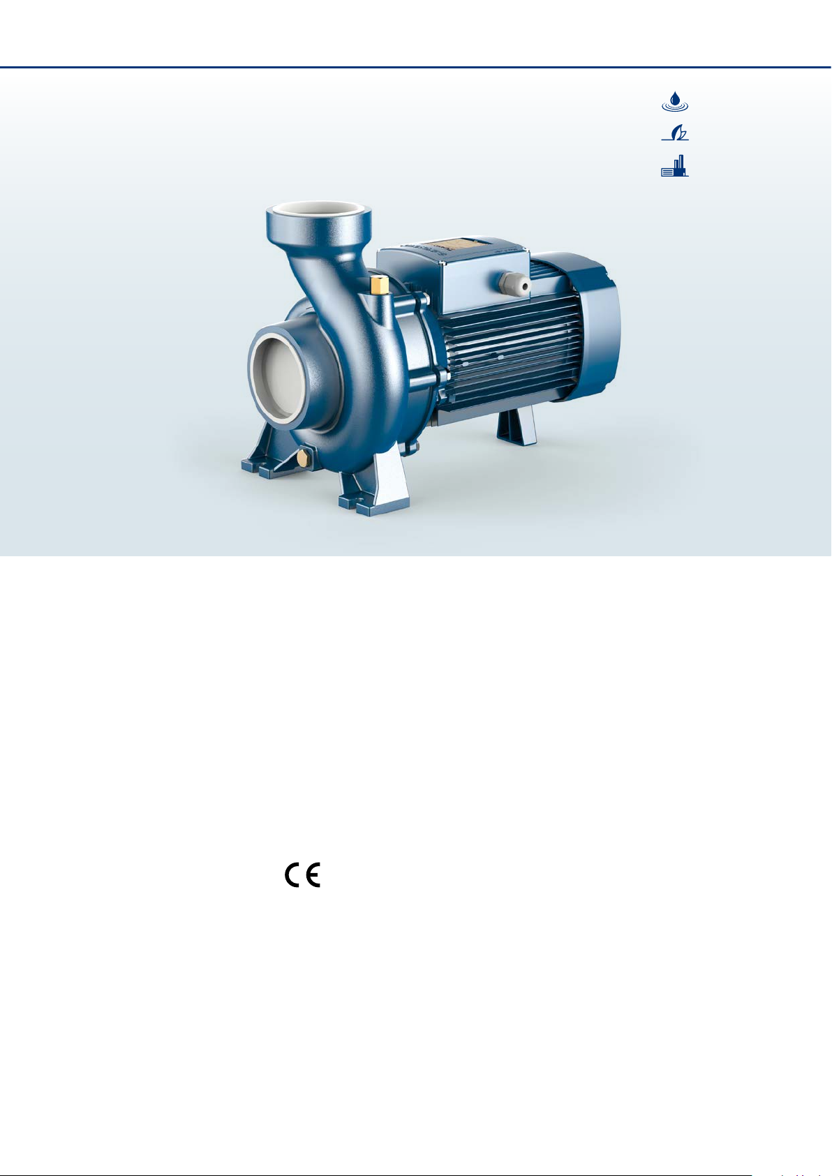
HF
Centrifugal pumps
High ow
➠
Clean water
Agricultural use
Industrial use
PERFORMANCE RANGE
• Flow rate up to 2200 l/min (132 m³/h)
• Head up to 24.5 m
APPLICATION LIMITS
• Manometric suction lift up to 7 m
• Liquid temperature between -10 °C and +90 °C
• Ambient temperature up to +40 °C
• Max. working pressure:
– 6 bar for HF 4
– 10 ba r for HF 6-8-20-30
• Continuous service S1
CONSTRUCTION AND SAFETY STANDARDS
EN 6 0335-1
IE C 60 335 -1
CE I 61-15 0
CERTIFICATIONS
Company with management system certied DNV
ISO 9001: QUALITY
EN 6 003 4-1
IE C 60 034 -1
CEI 2-3
INSTALLATION AND USE
Suitable for use in civil and agricultural applications. The high
eciency and continuous duty capabilities makes these pumps
ideal for use in activities such as ood and spray irrigation, drawing
water from lakes, rivers and wells, or for any number of dierent
industrial applications where the characteristics of high ow rates
and mid to low head are required.
The pump should be installed in an enclosed environment or
sheltered from inclement weather.
OPTIONS AVAILABLE ON REQUEST
• Pump body with NPT ANSI B 1.20.1 threaded ports
• Special mechanical seal
• Other voltages
GUARANTEE
2 years subject to terms and conditions
| 60 Hz |
66 | GENERAL CATALOGUE 60 Hz
Page 2
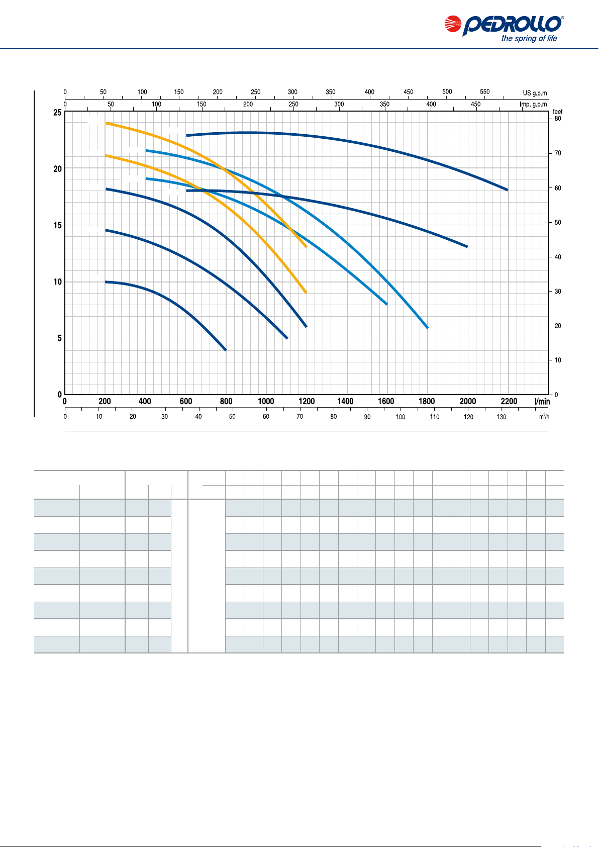
CHARACTERISTIC CURVES AND PERFORMANCE DATA 60 Hz n= 3450 min HS= 0 m
4
Head H (metres)
HF8A
HF8B
HF6A
HF6B
HF4
HF30A
HF20A
HF20B
HF30B
Flow rate Q
0 12 18 24 30 36 42 48 54 60 66 72 84 96 102 108 120 132
0 200 300 400 500 600 700 800 900 1000 1100 120 0 1400 1600 170 0 1800 2000 2200
10 10 9.8 9.4 8.6 7. 3 5.8 4
14.7 14.5 14 13.5 12. 8 12 11 9.7 8.2 6.7 5
18. 5 18.1 17.8 17. 2 16.8 16 15 13.8 12. 2 10.5 8.3 6
21.5 21 20.7 20 19.5 18 .8 17.8 16.5 15 13.5 11. 2 9
24.5 24 23.5 23 22.5 21.8 20.8 19. 5 18. 3 16.8 15 13
19 - - 19 18. 8 18 .5 18 17. 5 16.8 16 14. 5 13. 5 11 8
21.5 - - 21.5 21.3 21 20.5 19.8 19 18 17 16 13. 3 10 8 6
18 - - - - 18 18 18 18 18 17.5 17 16.5 15.5 15 14.5 13
23 - - - - 23 23 23 23 23 22.5 22.5 22.5 22 21.5 21 19.5 18
m³/ h
Q
l/min
MODEL POWER (P)
Single-ph. Three-ph.
kW HP
HFm 4 HF 4 0.75 1
HFm 6B HF 6B 1.5 2
HFm 6A HF 6A 2.2 3
– HF 8B 3 4
– HF 8A 4 5.5
IE3 H
metres
– HF 20B 3 4
– HF 20A 4 5.5
– HF 30B 5.5 7.5
– HF 30A 7.5 10
Q = Flow rate H = Total manometric head HS = Suction height Tolerance of characteristic curves in compliance with EN ISO 9906 Grade 3B.
Performance class of the three-phase motor (I EC 6 003 4-3 0-1)
4
GENERAL CATALOGUE 60 Hz | 67
| 60 Hz |
Page 3

HF
POS. COMPONENT CONSTRUCTION CHARACTERISTICS
1 PUMP BODY Cast iron complete with threaded ports in compliance with ISO 228/1
2 BODY BACKPLATE Cast iron (stainless steel AISI 304 for HF 4)
3 IMPELLER Stainless steel AISI 304 for HF 4
Brass for HF 6, HF 8
Cast iron for HF 20, HF 30
4 MOTOR SHAFT Stainless steel EN 10088-3 - 1.4104
5 MECHANICAL SEAL
6 BEARINGS
7 C APACITO R
8 ELECTRIC MOTOR HFm: single-phase 220 V - 60 Hz with thermal overload protector incorporated into the winding.
Pump Seal Shaft Materials
Model Model Diameter Stationary ring Rotational ring Elastomer
HF 4 AR -14 Ø 14 mm Ceramic Graphite NBR
HF 6 FN -18 Ø 18 mm Graphite Ceramic NBR
HF 8, HF 20 FN-20 Ø 20 mm Graphite Ceramic NBR
HF 30 FN-24 Ø 24 mm Graphite Ceramic NBR
Pump Model
HF 4 6203 ZZ / 6203 ZZ
HF 6 6304 ZZ / 6204 ZZ
HF 8B, HF 20B 6206 ZZ - C3 / 6205 ZZ
HF 8A, HF 20A 6306 ZZ - C3 / 6206 ZZ - C3
HF 30 6307 ZZ - C3 / 6206 ZZ - C3
Pump Capacitance
Single-phase
HFm 4 20 μF - 450 VL 60 μF - 300 VL
HFm 6B 45 μF - 450 VL 80 μF - 250 VL
HFm 6A 50 μF - 450 VL –
HF: three-phase 220/380 V - 60 Hz or 220/440 V - 60 Hz.
➠ The three-phase pump is fitted with a high performance motor in class IE3 (IEC 60034-30-1)
– Insulation: class F
– Protection: IP X4
(220 V) (110 V or 127 V)
1
3
4
| 60 Hz |
68 | GENERAL CATALOGUE 60 Hz
6
2 7
5
6
8
Page 4

DIMENSIONS AND WEIGHT
f
a
DN2
DN1
w
n
h2
h
h1
n1
s
MODEL PORTS DIMENSIONS mm kg
Single-phase Three-phase DN1 DN2 a f h h1 h2 n n1 w s 1~ 3~
HFm 4 HF 4 2½” 2½” 47 317 240 97 143 198 155 -68 10 14. 5 13.2
HFm 6B HF 6B
HF 6A 431 – 29.5
3” 3” 68
– HF 8B
– HF 8A 465 – 40.0
– HF 20B 455
– HF 20A 470 – 41.0
4” 4”
– HF 30B
– HF 30A – 65.2
80
77 534 370 160 210 292 212
411
445
312
120 192 240
245
132 180
255
190
6 12
30 14
26.5 25.5
– 35.0
– 36.0
– 60.9
ABSORPTION
MODEL VOLTAG E
Single-phase 220 V 110 V 127 V
HFm 4 6.6 A 13.2 A 12. 6 A
HFm 6B 12. 0 A 24.0 A 22.3 A
HFm 6A 14 .5 A – –
MODEL VOLTAG E
Three-phase 220 V 380 V 220 V 440 V
HF 4 5.0 A 2.9 A 4.2 A 2.4 A
HF 6B 8.6 A 5.0 A 7.6 A 4.2 A
HF 6A 10.7 A 6.2 A 9.0 A 4.8 A
HF 8B 12.0 A 7.0 A 13.0 A 7.0 A
HF 8A 18.2 A 10.5 A 18. 5 A 12.0 A
HF 20B-N 12.0 A 7.0 A 13.0 A 7.0 A
HF 20A-N 18.2 A 10.5 A 17. 8 A 11.0 A
HF 30B 22.5 A 13.0 A 20 .1 A 11.8 A
HF 30A 28.8 A 16.6 A 28.0 A 16.7 A
GENERAL CATALOGUE 60 Hz | 69
| 60 Hz |
 Loading...