


Operator’s Manual
Combination
Blanket/Fluid Warmer
P-2147
MN-39930
REV.01
3/19
EN

Manufacturer’s Information
Copyright © Copyright 3/19 by Pedigo Products, Inc.
All rights reserved.
This manual or any portion thereof may not be reproduced or used in any
manner whatsoever without the express written permission of Pedigo Products,
Inc.
Trademarks All trademarks referenced in this documentation are the property of their
respective owners.
Manufacturer Pedigo Products, Inc.
4000 S.E. Columbia Way
Vancouver, WA 98661, USA
1-800-822-3501
www.pedigo-usa.com
Original instructions The content in this manual is written in American English.
Combination Blanket/Fluid Warmer ▪ Operator’s Manual ▪ MN-39930 ▪ Rev 1 ▪ 3/19
2

FOREWORD
Thank you for your Purchase!
This warmer has been thoroughly tested and inspected to ensure only the
highest quality is provided. We supply the most durable, convenient, efficient
and safe warming equipment on the market. All warmers are manufactured and
fully inspected in the USA with a commitment to quality.
Pedigo Repair Service
Call Call 262-509-6517 to reach our service call center for immediate access to local
authorized service agencies. This service is provided exclusively for Pedigo
Product, Inc. equipment and is available throughout the United States.
Combination Blanket/Fluid Warmer ▪ Operator’s Manual ▪ MN-39930 ▪ Rev 1 ▪ 3/19
OREWORD
3

FOREWORD
This page intentionally left blank
Combination Blanket/Fluid Warmer ▪ Operator’s Manual ▪ MN-39930 ▪ Rev 1 ▪ 3/19
4

TABLE OF CONTENTS
Manufacturer’s Information . . . . . . . . . . . . . . . . . . . . . . . . 2
Foreword 3
Thank you for your Purchase! . . . . . . . . . . . . . . . . . . . . . . . 3
Pedigo Repair Service . . . . . . . . . . . . . . . . . . . . . . . . . . . . 3
Table of Contents 5
Safety 7
The Meaning of Signal Words . . . . . . . . . . . . . . . . . . . . . . . 7
Safety Precautions. . . . . . . . . . . . . . . . . . . . . . . . . . . . . . 8
Labels 11
Label Locations . . . . . . . . . . . . . . . . . . . . . . . . . . . . . . . 11
Specifications 13
Specification Information . . . . . . . . . . . . . . . . . . . . . . . . . 13
Dimension Drawings . . . . . . . . . . . . . . . . . . . . . . . . . . . . 14
Installation 17
How to Unpack the Warmer . . . . . . . . . . . . . . . . . . . . . . . . 17
How to Install the Warmer . . . . . . . . . . . . . . . . . . . . . . . . . 18
Operation 21
Preparing the Warmer for First Use. . . . . . . . . . . . . . . . . . . . 21
How to Turn On and Turn Off the Warmer . . . . . . . . . . . . . . . . 22
How to Operate the Blanket Warmer (Bottom Cavity) . . . . . . . . . 23
How to Operate the Fluid Warmer (Top Cavity) . . . . . . . . . . . . . 24
How to Change the Temperature Scale. . . . . . . . . . . . . . . . . . 26
How to Change the Sound Settings . . . . . . . . . . . . . . . . . . . . 26
How to Lock and Unlock the Controller. . . . . . . . . . . . . . . . . . 27
How to Download Temperature Data from the Warmer . . . . . . . . 28
Maintenance 31
Maintenance Schedule . . . . . . . . . . . . . . . . . . . . . . . . . . . 31
How to Clean the Warmer . . . . . . . . . . . . . . . . . . . . . . . . . 32
Troubleshooting 35
What to do if a Power Interruption Occurs. . . . . . . . . . . . . . . . 35
What to do if the Alarm Indicator Light Flashes . . . . . . . . . . . . . 36
Error Codes. . . . . . . . . . . . . . . . . . . . . . . . . . . . . . . . . . 37
How to Replace a Fuse . . . . . . . . . . . . . . . . . . . . . . . . . . . 41
ONTENTS
C
OF
Electrical Information 43
Warranty 47
Warranty . . . . . . . . . . . . . . . . . . . . . . . . . . . . . . . . . . . 47
Combination Blanket/Fluid Warmer ▪ Operator’s Manual ▪ MN-39930 ▪ Rev 1 ▪ 3/19
ABLE
T
5

TABLE OF CONTENTS
This page intentionally left blank
Combination Blanket/Fluid Warmer ▪ Operator’s Manual ▪ MN-39930 ▪ Rev 1 ▪ 3/19
6

The Meaning of Signal Words
This manual contains signal words where needed. These signal words must be
obeyed to reduce the risk of death, personal injury, or equipment damage. The
meaning of these signal words is explained below.
DANGER
Danger indicates a hazardous situation which, if not avoided,
will result in serious injury or death.
WARNING
Warning indicates a hazardous situation which, if not avoided,
could result in serious injury or death.
SAFETY
CAUTION
Caution indicates a hazardous situation which, if not avoided,
could result in minor or moderate injury.
NOTICE
NOTE: Note indicates additional information that is important to a
concept or procedure.
Notice indicates a situation which, if not avoided, could result
in property damage.
Combination Blanket/Fluid Warmer ▪ Operator’s Manual ▪ MN-39930 ▪ Rev 1 ▪ 3/19
AFETY
7

SAFETY
Safety Precautions
Before you begin Read and understand all instructions in this manual.
Electrical precautions Obey these electrical precautions when using the warmer:
▪ Connect the warmer to a properly grounded outlet. Do not use the warmer if it is
not properly grounded. Consult an electrician if there is any doubt that the outlet
used is properly grounded.
▪ Keep the cord away from hot surfaces.
▪ Do not attempt to service the warmer or its cord and plug, when plugged in.
▪ Do not operate the warmer if it has a damaged cord or plug.
▪ Do not immerse the cord or plug in water.
▪ Do not let the cord hang over the edge of a table or counter.
▪ Do not use an extension cord.
Usage precautions Obey these usage precautions when using the warmer:
▪ Only use this warmer for its intended use of warming.
▪ Do not use this warmer for warming blood or blood products.
▪ Do not cover or block any of the openings of this warmer.
▪ Do not use this warmer in a wet location.
▪ Only clean the warmer when the power cord is unplugged.
▪ Do not use corrosive chemicals when cleaning the warmer.
▪ Do not use the warmer cavity for storage.
▪ Do not remove the top cover or exterior side panels. There are no user-
serviceable components inside.
Operator training All personnel using the warmer must have proper operator training. Before
using the warmer:
▪ Read and understand the operating instructions contained in all the
documentation delivered with the warmer.
▪ Know the location and proper use of all controls.
▪ Keep this manual and all supplied instructions, diagrams, schematics, parts lists,
notices, and labels with the warmer if the warmer is sold or moved to another
location.
Combination Blanket/Fluid Warmer ▪ Operator’s Manual ▪ MN-39930 ▪ Rev 1 ▪ 3/19
8

SAFETY
Operator
qualifications
Only trained personnel with the following operator qualifications are permitted
to use the warmer:
▪ Have received proper instruction on how to use the warmer.
▪ Are familiar with the purpose, limitations, and associated hazards of the warmer.
The warmer must not be used by:
▪ People impaired by drugs or alcohol.
Condition of warmer Only use the warmer when:
▪ All controls operate correctly.
▪ The warmer is installed correctly.
▪ The warmer is clean.
▪ The warmer labels are legible.
Servicing the warmer ▪ Obey precautions in the manual, on tags, and on labels attached to or shipped
with the warmer.
▪ Only trained personnel are permitted to service or repair the warmer. Repairs
that are not performed by a trained technician, or the use of non-factory parts,
will void the warranty and relieve all liability.
▪ Any troubleshooting guides and components views included with this manual
are for reference only and are intended for use by qualified and trained service
technicians.
▪ To prevent serious injury, death or property damage, have the warmer inspected
and serviced at least every twelve (12) months by a trained technician.
▪ Contact Pedigo for the authorized service partner in your area.
Combination Blanket/Fluid Warmer ▪ Operator’s Manual ▪ MN-39930 ▪ Rev 1 ▪ 3/19
9

SAFETY
This page intentionally left blank
10
Combination Blanket/Fluid Warmer ▪ Operator’s Manual ▪ MN-39930 ▪ Rev 1 ▪ 3/19

Label Locations
LABELS
a
b
c
d
EC-PHD-004613
Combination Blanket/Fluid Warmer ▪ Operator’s Manual ▪ MN-39930 ▪ Rev 1 ▪ 3/19
ABELS
11

LABELS
Security Seal
Security Seal
Security Seal
Security Seal
Security Seal
Security Seal
Security Seal
Security Seal
1
Security seal
Electrical warning label
2
Pedigo contact information
3
Quality inspected
4
12
Combination Blanket/Fluid Warmer ▪ Operator’s Manual ▪ MN-39930 ▪ Rev 1 ▪ 3/19

Specification Information
E471516
Protective Earth
Ground Symbol
SPECIFICATIONS
Transportation and
storage conditions
Weight
Storage cavity capacity
Temperature range
Clearance
requirements
▪ Ambient temperature range of -40°F to +159°F (-40°C to +70°C).
▪ Relative humidity range of 10% to 95%, non-condensing.
▪ Atmospheric pressure range of 7.25 psi to 15.37 psi (50kPa to 106kPa).
Net: 457 lb (207 kg)
Ship: 568 lb (258 kg)
Fluid cavity: 30 1-liter bottles or 24 1-liter bags
3
Blanket cavity: 30 blankets (13 ft
Irrigation fluids (IRR):
90°F to 150°F (32°C to 66°C)
Injection fluids (INJ):
90°F to 104°F (32°C to 40°C)
Blanket: 90°F to 160°F (32°C to 71°C)
4” (102mm) from rear
1” (25mm) from top
2” (51mm) from sides
1/2” (13mm) from bottom
)
Operating conditions ▪ The warmer must acclimate to the room temperature it will be placed—24 hours
is recommended.
▪ The recommended environmental temperature range is 60°F to 90°F
(15°C to 32°C).
▪ The recommended relative humidity is above 20%, non-condensing.
Standards for
electrical equipment
Combination Blanket/Fluid Warmer ▪ Operator’s Manual ▪ MN-39930 ▪ Rev 1 ▪ 3/19
▪ Medical equipment classified by Underwriters Laboratories with respect
to electrical shock, fire, and mechanical hazards only, in accordance with
UL 61010-1 and CAN/CSA C22.2 No. 61010-1.
▪ Grounding reliability can only be achieved when the appliance is
connected to an equivalent receptacle marked “Hospital Grade.”
▪ IEC 60601-1-2
▪ IP-XO ordinary
PECIFICATIONS
13

SPECIFICATIONS
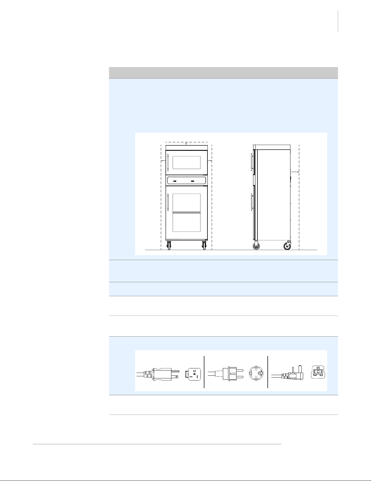
EC-DIM-004602
68.75
"
(1743mm)
68.10
"
(1729mm)
30" (763mm)
15
"
(381mm)
CAVITY & INSERT
26.5"
(673mm)
CAVITY
23.60" (598mm)
INSERT
36
"
(914mm)
CAVITY
35
"
(890mm)
INSERT
23.60" (598mm)
INSERT
58.75" (1492mm)
29.25
"
(743mm)
56
"
(1422mm)
26.5" (673mm)
28.25" (715mm)
43.30
"
(1100mm)
IEC Cord Inlet
23.75" (603mm)
CAVITY
23.75" (603mm)
CAVITY
Dimension Drawings
Warmer shown with feet
14
Combination Blanket/Fluid Warmer ▪ Operator’s Manual ▪ MN-39930 ▪ Rev 1 ▪ 3/19

Warmer shown with casters
(1422mm)
"
56
(743mm)
"
29.25
58.75"
(1492mm)
30" (763mm)
26.5" (673mm)
CAVITY
(381mm)
"
15
CAVITY & INSERT
"
(721mm)
28.5
26.5" (673mm)
23.75
"
(603mm)
CAVITY
SPECIFICATIONS
(1727mm)
(1901mm)
"
"
68
75
23.60" (598mm)
INSERT
23.60" (598mm)
INSERT
(890mm)
INSERT
"
35
(914mm)
CAVITY
"
36
23.75
" (603mm)
CAVITY
EC-DIM-004605
(1256mm)
"
IEC Cord Inlet
49.5
Combination Blanket/Fluid Warmer ▪ Operator’s Manual ▪ MN-39930 ▪ Rev 1 ▪ 3/19
15

SPECIFICATIONS
This page intentionally left blank
16
Combination Blanket/Fluid Warmer ▪ Operator’s Manual ▪ MN-39930 ▪ Rev 1 ▪ 3/19

How to Unpack the Warmer
Step Action
Before you begin Make sure you have:
▪ An appropriate lifting device and enough personnel to safely move and position
the weight of the warmer.
▪ Cutting tools to remove the packaging.
Unpack the warmer To unpack the warmer, do the following.
1. Remove the box or crate. Save all packing materials for inspection by the
carrier.
NOTE: Examine the warmer for damage. If the warmer has
been damaged, do not use the warmer until it has been
inspected by an authorized service provider. Contact your
carrier or customer service.
INSTALLATION
2. Cut and remove the retaining straps and plastic wrap.
3. Remove the warmer from the pallet using an appropriate lifting device.
4. Remove the paperwork from the cavity.
Result The warmer is now unpacked.
Combination Blanket/Fluid Warmer ▪ Operator’s Manual ▪ MN-39930 ▪ Rev 1 ▪ 3/19
NSTALLATION
17

INSTALLATION
How to Install the Warmer
Before you begin Make sure you have:
An appropriate lifting device and enough personnel to safely move and position
the weight of the warmer.
Requirements
Voltages
▪ The warmer must be installed on a level surface.
▪ The warmer must not be installed in any area where it may be affected by
dripping water, high temperature, or any other severely adverse conditions.
Model V Ph Hz kW Plug Configuration
P-2147 120
220
230
*Other international plugs are available, contact the manufacturer for more
information.
1
1
1
50/60
50/60
50/60
1.3
1.2
1.3
NEMA 5-20P
CEE 7/7*
BS 1363 (UK only)
CEE 7/7*
Continued on next page
18
Combination Blanket/Fluid Warmer ▪ Operator’s Manual ▪ MN-39930 ▪ Rev 1 ▪ 3/19
Continued from previous page
Step Action
EC-DIM-004616
1.0"
25mm
2.0"
51mm
2.0"
51mm
4.0"
102mm
CEE 7/7NEMA 5-20P BS 1363
EC-TS-004622
Position the warmer To position the warmer, do the following.
1. Make sure that:
▪ The location where the warmer is being installed is rated to support the
weight of the warmer;
▪ The warmer is within five feet of the appropriate electrical outlet;
▪ You follow the warmer clearance guidelines shown below.
INSTALLATION
2. Move the warmer to the installation location and onto the final resting
surface.
3. Lock the casters, if equipped.
The warmer is now correctly positioned.
Connect power
To connect electric power to the warmer, do the following.
4. Connect the plug to the electrical outlet.
Result The warmer is now installed and ready to be used.
Combination Blanket/Fluid Warmer ▪ Operator’s Manual ▪ MN-39930 ▪ Rev 1 ▪ 3/19
19

INSTALLATION
This page intentionally left blank
20
Combination Blanket/Fluid Warmer ▪ Operator’s Manual ▪ MN-39930 ▪ Rev 1 ▪ 3/19

Preparing the Warmer for First Use
Step Action
Before you begin
CAUTION: Burn hazard.
Allow the warmer to cool before cleaning.
OPERATION
NOTICE
Procedure
Result The warmer is now ready for use.
To prepare the warmer for first use, do the following.
1. Make sure that the warmer is turned off and cool.
2. Wipe the outside of the warmer with a stainless steel cleaner.
3. Clean the interior of the warmer with a damp cloth.
4. Dry the interior and exterior of the warmer with a clean, lint-free cloth.
Leave the door open until the interior of the warmer completely dries.
5. Clean each side of the window pane with glass cleaner or distilled vinegar.
Do not use:
▪ abrasive cleaning compounds.
▪ chloride based cleaners.
▪ commercial or household cleaners containing ammonia.
▪ cleaners containing quaternary salts.
Combination Blanket/Fluid Warmer ▪ Operator’s Manual ▪ MN-39930 ▪ Rev 1 ▪ 3/19
PERATION
21
OPERATION
Step Action
EC-TS-004628
a
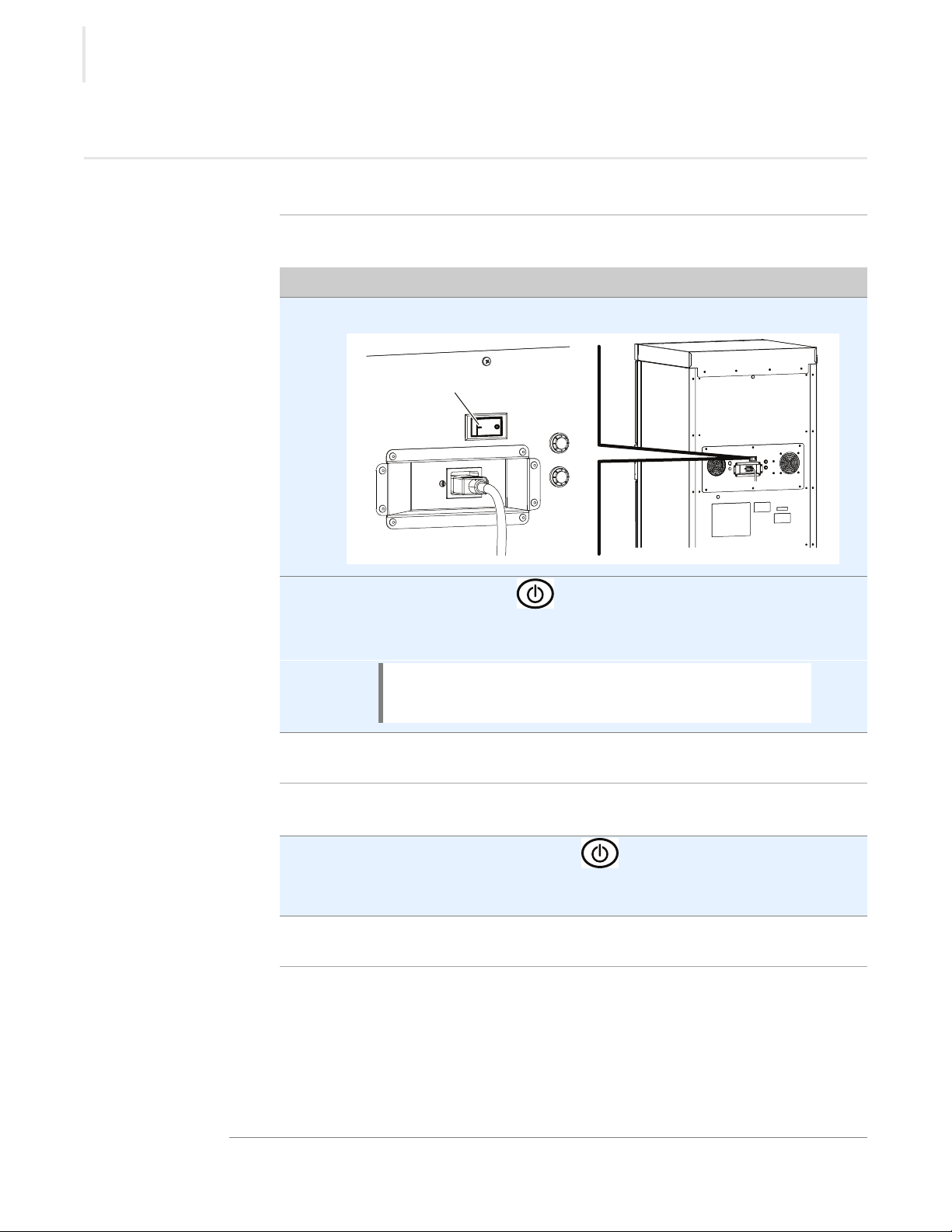
How to Turn On and Turn Off the Warmer
Before you begin The warmer must be connected to electric power.
Turning on the
warmer
To turn on the warmer, do the following.
1. Set the power switch a to the ON (l) position.
2. Press the ON/OFF button . The screen turns on.
The blanket warmer and fluid warmer screens must be turned ON
separately.
NOTE: A temporary odor may be noticeable upon initial
start-up of the warmer. Contact the manufacturer if the
odor persists after a day or more of continuous use.
Turning off the
warmer
22
The warmer is now on.
To turn off the warmer, do the following.
3. Press and hold the ON/OFF button until the screen turns off.
The blanket warmer and fluid warmer screens must be turned OFF
separately.
The warmer is now off.
Combination Blanket/Fluid Warmer ▪ Operator’s Manual ▪ MN-39930 ▪ Rev 1 ▪ 3/19
OPERATION
Step Action
How to Operate the Blanket Warmer (Bottom
Cavity)
Before you begin The warmer must be connected to electric power and turned on.
WARNING: Personal injury hazard.
Do not operate the warmer in the presence of flammable
anesthetic mixtures (with air or with oxygen or nitrous oxide).
WARNING: Personal injury hazard.
Make sure the blanket support assembly and shelves are
installed to prevent the blankets from being scorched or
discolored.
Procedure
During the warming
process
NOTICE
To operate the warmer, do the following.
1. Set the temperature using the arrow buttons .
2. Open the door and load the dry, cotton blankets into the warmer.
Close the door.
3. Press the temperature recall button to view the actual temperature.
The actual temperature will display for five seconds. Then, the set-point
temperature will display.
4. Rotate the blankets daily from the bottom to the top of the load to ensure
equal heating and to prevent discoloration.
Do not overload the cavity.
Allow 1” (25mm) between the blankets and the interior walls.
NOTE: The temperature set-point range is 90°F – 160°F
(32°C – 71°C).
NOTICE
Do not warm items containing plastic, rubber, metal
snaps, studs, hooks, etc.
Result The blankets are now warming.
Combination Blanket/Fluid Warmer ▪ Operator’s Manual ▪ MN-39930 ▪ Rev 1 ▪ 3/19
23

OPERATION
Step Action
How to Operate the Fluid Warmer (Top Cavity)
Before you begin The warmer must be connected to electric power and turned on.
WARNING: Personal injury hazard.
Do not operate the warmer in the presence of flammable
anesthetic mixtures (with air or with oxygen or nitrous oxide).
WARNING: Personal injury hazard.
Verify the fluid temperature prior to using the fluid. Refer to the
fluid manufacturer’s label for recommended warming
procedures.
Do not use any fluids that are warmed above the suggested
temperature.
Procedure
NOTICE
Do not overload the cavity.
Refer to topic Specification Information for the storage cavity
capacity.
To operate the warmer, do the following.
1. Select the operation mode.
▪ Press the irrigation button for irrigation mode.
▪ Press the injection button for injection mode.
The selected operation mode will illuminate .
NOTE: Open the door to cool the cavity before changing
from a higher temperature to a lower temperature.
2. Set the temperature using the arrow buttons .
NOTE: The irrigation temperature set-point range is
90°F – 150°F (32°C – 66°C).
The injection temperature set-point range is 90°F – 104°F
(32°C – 40°C).
24
Continued on next page
Combination Blanket/Fluid Warmer ▪ Operator’s Manual ▪ MN-39930 ▪ Rev 1 ▪ 3/19

Continued from previous page
3. Open the door and load the fluid into the warmer.
Close the door.
OPERATION
During the warming
process
4. Press the temperature recall button to view the actual temperature.
The actual temperature will display for five seconds. Then, the set-point
temperature will display.
Result The fluids are now warming.
Combination Blanket/Fluid Warmer ▪ Operator’s Manual ▪ MN-39930 ▪ Rev 1 ▪ 3/19
25

OPERATION
Step Action
Step Action
How to Change the Temperature Scale
Before you begin The warmer must be connected to electric power and the screen turned off.
Procedure
Result The temperature scale has now been changed.
To change the temperature scale from °F to °C and vice versa, do the following.
1. Press and hold the ON/OFF button until the screen turns off.
2. Press and hold the temperature recall button to display the current
temperature scale.
3. Press the up and down arrow buttons to toggle between the
temperature scales.
How to Change the Sound Settings
Before you begin The warmer must be connected to electric power and the screen turned off.
Procedure
Result The sound setting has now been changed.
26
To change the sound settings, do the following.
1. Press and hold the ON/OFF button until the screen turns off.
2. Press and hold the temperature recall button , then the down arrow
button .
The sound setting displays.
3. Press the up and down arrow buttons to adjust the volume.
The volume range is 0 (mute) to 12 (maximum).
Combination Blanket/Fluid Warmer ▪ Operator’s Manual ▪ MN-39930 ▪ Rev 1 ▪ 3/19

OPERATION
Step Action
How to Lock and Unlock the Controller
Before you begin The warmer must be turned on (screen is on).
Background The controller can be locked to prevent changes being made to the temperature
set-point.
Locking the
controller
Unlocking the
controller
Result The controller has now been locked or unlocked.
To lock the controller, do the following.
1. Press the ON/OFF button and the up arrow button at the same
time.
The lock indicator will illuminate.
To unlock the controller, do the following.
2. Press the ON/OFF button and the down arrow button at the
same time.
The lock indicator goes off.
Combination Blanket/Fluid Warmer ▪ Operator’s Manual ▪ MN-39930 ▪ Rev 1 ▪ 3/19
27

OPERATION
Step Action
How to Download Temperature Data from the Warmer
Before you begin ▪ The warmer must be turned on (screen is on).
▪ Do not remove the USB drive during the download process.
▪ You will need a SanDisk Cruzer Glide USB drive.
NOTICE
Background The warmer automatically downloads only the data that has not been previously
downloaded. The warmer will store multiple years of data. The download time
for one week of data should be under five seconds.
The warmer records various performance parameters:
▪ automatically every five minutes while the power switch is ON.
▪ each time the temperature set-point is changed.
▪ each time the fluid door is opened.
▪ each time the fluid operation mode is changed.
Procedure To download temperature data from the warmer, do the following.
1. Open the blanket warmer door.
Only use a SanDisk Cruzer Glide USB drive larger than 4 GB.
Using other USB drives may cause erratic operation or loss of
data.
Continued on next page
28
Combination Blanket/Fluid Warmer ▪ Operator’s Manual ▪ MN-39930 ▪ Rev 1 ▪ 3/19

OPERATION
EC-TS-005823
a
Continued from previous page
2. Plug the USB drive into the port a. The warmer downloads the temperature
data.
NOTICE
The warmer goes through the download process:
▪ The LED screen located above the USB port flashes for a few seconds to
show a data transfer is in progress.
▪ The LED screen stops flashing.
▪ The download is complete.
3. Remove the USB drive from the port.
4. Close the blanket warmer door.
Do not remove the USB drive during the download
process.
Result The data has now been downloaded.
Viewing the
To view the temperature data, do the following.
temperature data
5. Plug the USB drive into a computer.
6. Double-click on the file.
NOTE: Data is stored on the USB drive in a file named,
datalog_MMDDYY_HHMMSS.csv.
7. Sort the data as necessary.
Temperature data will be recorded in the same temperature units that are
displayed on the LED screen.
NOTE: Errors recorded by the warmer are intended for
use by service technicians only.
Combination Blanket/Fluid Warmer ▪ Operator’s Manual ▪ MN-39930 ▪ Rev 1 ▪ 3/19
Continued on next page
29

OPERATION
Continued from previous page
Viewing data in
The table below is an example of temperature data from the warmer.
Microsoft Excel
Time Stamp Chamber Mode Power Door Fan Temperature Set-point Errors
12/19/2018 14:48 bottom off closed off 71.7 130 Diagnostics.SensorSho
rtErrors=0x0c
12/19/2018 14:48 top off closed off 71.2 104 Diagnostics.SensorSho
rtErrors=0x0c
12/19/2018 14:53 bottom on closed on 71.7 130 Diagnostics.SensorSho
rtErrors=0x0c
12/19/2018 14:53 top INJ on closed on 70.4 104 Diagnostics.SensorSho
rtErrors=0x0c
12/19/2018 14:58 bottom on closed on 71.7 130 Diagnostics.SensorSho
rtErrors=0x0c
12/19/2018 14:58 top INJ on closed on 70.4 104 Diagnostics.SensorSho
rtErrors=0x0c
12/19/2018 15:03 bottom on closed on 71.7 130 Diagnostics.SensorSho
rtErrors=0x0c
12/19/2018 15:03 top INJ on closed on 70.3 104 Diagnostics.SensorSho
rtErrors=0x0c
Result The temperature data has now been viewed.
30
Combination Blanket/Fluid Warmer ▪ Operator’s Manual ▪ MN-39930 ▪ Rev 1 ▪ 3/19

Maintenance Schedule
Daily For daily maintenance, do the following.
Check:
▪ the air vents in the airflow insert panels are not obstructed (if applicable).
▪ all fan guards are clear and not obstructed (if applicable).
▪ the number of bottles, bags, or blankets do not exceed the maximum capacity
per shelf or basket.
Clean:
▪ any spills with a clean, lint free cloth.
Monthly For monthly maintenance, do the following.
Check:
▪ the door gasket for tears and holes. Make sure that it is firmly attached to the
door. Check the seal when the door is closed.
▪ the guards around the air temperature sensor are in place and fully secure to the
warmer.
▪ the hardware securing the warmer(s) to the wall, if applicable.
Clean:
MAINTENANCE
▪ the outside of the warmer with stainless steel cleaner.
▪ vacuum (if applicable):
□ fan openings
□ fan sail switch
□ vent openings
Yearly For yearly maintenance, do the following.
Check:
▪ the set-point temperature compared to the actual temperature displayed.
□ Check the cavity air temperature with a thermocouple placed 1” (25mm) from
the cavity sensor. Do not allow the thermocouple to touch any surface.
Monitor the temperature for approximately one hour in an empty cavity.
▪ the condition of the plug and cord and replace if damaged.
▪ the controller screen for excessive wear. Make sure the controller screen displays
and operates properly.
Clean:
▪ the shelves and interior of the warmer.
AINTENANCE
Combination Blanket/Fluid Warmer ▪ Operator’s Manual ▪ MN-39930 ▪ Rev 1 ▪ 3/19
31
MAINTENANCE
Step Action
How to Clean the Warmer
Before you begin
WARNING: Electric shock hazard.
Disconnect the warmer from electric power before cleaning.
CAUTION: Burn hazard.
Allow the warmer to cool before cleaning.
Monthly cleaning
procedure
NOTICE
Do not use:
▪ abrasive cleaning compounds.
▪ chloride based cleaners.
▪ commercial or household cleaners containing ammonia.
▪ cleaners containing quaternary salts.
To clean the warmer monthly, do the following.
1. Make sure that the warmer is disconnected from electric power and cool.
2. Wipe the outside of the warmer with a stainless steel cleaner.
3. Vacuum lint from fan openings, fan sail switch, and vent openings.
4. Clean the interior of the warmer with a damp cloth.
5. Dry the interior and exterior of the warmer with a clean, lint-free cloth.
Leave the door open until the interior of the warmer completely dries.
6. Clean each side of the window pane with glass cleaner or distilled vinegar.
32
Continued on next page
Combination Blanket/Fluid Warmer ▪ Operator’s Manual ▪ MN-39930 ▪ Rev 1 ▪ 3/19
Continued from previous page
Step Action
EC-TS-004655
a
a
EC-TS-004658
b
MAINTENANCE
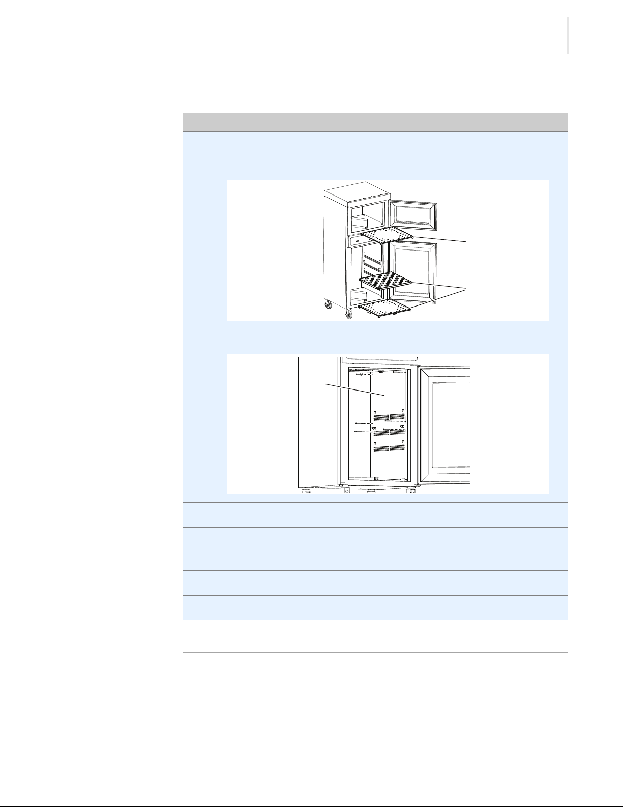
Yearly cleaning
procedure
To clean the warmer yearly, do the following.
1. Make sure that the warmer is disconnected from electric power and cool.
2. Remove the shelves a from the interior of the warmer.
3. Remove the side panels b from the interior of the blanket warmer cavity.
Result The warmer is now clean.
Combination Blanket/Fluid Warmer ▪ Operator’s Manual ▪ MN-39930 ▪ Rev 1 ▪ 3/19
4. Clean the shelves and interior with a damp cloth.
5. Dry the interior of the warmer with a clean, lint-free cloth.
Leave the door open until the interior of the warmer completely dries.
6. Clean each side of the window pane with glass cleaner or distilled vinegar.
7. Re-install the side panels and shelves.
33

MAINTENANCE
This page intentionally left blank
34
Combination Blanket/Fluid Warmer ▪ Operator’s Manual ▪ MN-39930 ▪ Rev 1 ▪ 3/19

TROUBLESHOOTING
Step Action
LED
What to do if a Power Interruption Occurs
Background You may need to reset the warmer in the case that a power interruption occurs.
When the power is restored, the ON/OFF status indicator LED decimal
flashes .
The controller stores all settings and continues operation using these settings in
the event of a power interruption.
Procedure
Result Resume operation of the warmer.
To continue operation of the warmer, do the following.
1. Press the ON/OFF button .
The LED goes out.
NOTE: The screen displays the length of time of the
power interruption in hours and minutes (hh:mm) for five
seconds. Then, the screen displays the set-point
temperature.
2. Make sure the fluids and blankets are at the correct temperature before
using.
Combination Blanket/Fluid Warmer ▪ Operator’s Manual ▪ MN-39930 ▪ Rev 1 ▪ 3/19
ROUBLESHOOTING
35

TROUBLESHOOTING
Step Action
What to do if the Alarm Indicator Light Flashes
Background The alarm indicator light flashes and the controller sounds an alarm when
the warmer malfunctions.
Procedure
Result Resume operation of the warmer.
If the alarm indicator light flashes, do the following.
1. Press the ON/OFF button to acknowledge the alarm.
Refer to the troubleshooting section for the error code.
2. Make sure the fluids and blankets are the correct temperature before using.
36
Combination Blanket/Fluid Warmer ▪ Operator’s Manual ▪ MN-39930 ▪ Rev 1 ▪ 3/19

TROUBLESHOOTING
Error Codes
Background This section is provided for the assistance of qualified and trained service
technicians only and is not intended for use by untrained or unauthorized service
personnel. Failure to observe this precaution may void the warranty.
NOTE: If the warmer is not operating properly, check the following
before calling an authorized service agent:
Verify that the power to the warmer is on.
If applicable, ensure the female end of plug is securely seated in the
warmer and that the male end of plug is in an appropriate,
functioning outlet.
If applicable, examine the fuses. Replace the fuses, refer to topic How
to Replace a Fuse.
If applicable, examine the high limit manual reset button. If the high
limit manual reset button is tripped, reset the warmer, refer to topic
How to Manually Reset the Warmer.
NOTE: All non-critical codes can be cleared using the ON/OFF button.
Critical errors (marked with a *) can only be cleared by setting the
power switch at the rear of the warmer to the off (O) position and
allowing the warmer to cool.
NOTICE
Code Refers to Action required
Display flashes
set point
Cavity
temperature
higher than set
point
Do not attempt to repair or service the warmer beyond this
point. Contact the manufacturer for the nearest authorized
service agent. Repairs made by any other service agent
without prior authorization by the manufacturer will void the
warranty.
Cavity temperature is higher than the set point temperature.
◾Allow cavity to cool to set point temperature.
Combination Blanket/Fluid Warmer ▪ Operator’s Manual ▪ MN-39930 ▪ Rev 1 ▪ 3/19
37

TROUBLESHOOTING
Code Refers to Action required
E-10
ES10
ES20
ES30
ES40
ES50
ES60
ES70
E-11
ES11
ES21
ES31
ES41
ES51
ES61
ES71
Cavity sensor
Sensor 1
Sensor 2
Sensor 3
Sensor 4
Sensor 5
Sensor 6
Sensor 7
Cavity sensor
Pad sensor 1
Pad sensor 2
Pad sensor 3
Pad sensor 4
Pad sensor 5
Pad sensor 6
Pad sensor 7
Sensor is shorted. Software disengages heating pads. Acknowledge error
by pressing the ON/OFF button. If error persists, a qualified service
technician should test the sensor.
◾Test the sensor. Detach the sensor from the warmer. Use an Ohm meter
to measure the resistance of the sensor. Check the sensor at 25°C (77°F).
If the reading is 10 KOhm ±1.5 KOhm, replace the display. If the reading
is ±2 KOhm, replace the sensor.
◾Check the wires for integrity. Inspect the connections at the control and
terminal block to ensure proper and secure connections. If necessary,
re-secure the faulty connections.
◾Contact service if error persists.
Sensor is open. Software disengages heating pads. Acknowledge error by
pressing the ON/OFF button. If error persists, a qualified service technician
should test the sensor.
◾Test the sensor. Disconnect the sensor from the warmer control PCB
and use an Ohm meter to measure the resistance of the sensor.
Sensor PR-37140 should measure 10 KOhm ± 1.5 KOhm at 25°C (77°F).
Sensor SN-33541 should measure 100 Ohm ± 10 Ohm at 25°C (77°F).
Replace sensor if measurement is outside of tolerance.
◾Check the wires for integrity. Check for proper and secure connections
at the control and terminal block. If necessary, re-secure the faulty
connections.
◾Contact service if error persists.
E-30 Under
temperature
*E-31 Cavity sensor
The blanket cavity temperature is lower than the set temperature for 90
minutes or longer.
◾Make sure the door is closed.
◾If the cavity is overloaded, redistribute the inventory. Do not exceed the
height of the insert.
◾Test the sensor. Disconnect the sensor from the warmer control PCB
and use an Ohm meter to measure the resistance of the sensor.
Sensor PR-37140 should measure 10 KOhm ± 1.5 KOhm at 25°C (77°F).
Sensor SN-33541 should measure 100 Ohm ± 10 Ohm at 25°C (77°F).
Replace sensor if measurement is outside of tolerance.
◾The sensor reading is above the temperature set-point. Blanket warmer
triggers at 15° over set-point. Fluid warmer triggers at 5° over set-point.
◾The difference between the room temperature and the fluid set-point
temperature must be greater than 11°C (20°F).
◾Contact service if error persists.
38
Combination Blanket/Fluid Warmer ▪ Operator’s Manual ▪ MN-39930 ▪ Rev 1 ▪ 3/19

Code Refers to Action required
TROUBLESHOOTING
P131
P231
P331
P431
P531
P631
P731
Pad sensor 1
Pad sensor 2
Pad sensor 3
Pad sensor 4
Pad sensor 5
Pad sensor 6
Pad sensor 7
*E-33 Cavity sensor
*E-50 Analog to Digital
Converter Error
E-60 Real Time Clock
Checksum Error
(Blanket warmers only)
*E-61 Real Time Clock
(Blanket warmers only)
Heater pad over-temp error.
◾Software disengages heating pads.
◾Acknowledge error by pressing the ON/OFF button.
◾Allow the warmer to cool.
◾Contact service if the error persists.
◾Sensor reading is above maximum allowable temperature set-point and
over temp value. Blanket warmers trigger at 82°C (180°F). Fluid warmers
trigger at 71°C (160°F).
◾Contact service if error persists.
◾Remove inventory, discard if necessary, and allow the warmer to cool
down.
◾If error persists after cool down and reset, the control assembly should
be replaced by a qualified service technician. Contact service.
Real time clock rechargeable battery backup has discharged.
◾Plug the warmer into the outlet for 30 minutes.
Real time clock not responding. Contact service if error persists.
E-62 Real Time Clock
(Blanket warmers only)
Timer overlay is present, but no real time clock is detected. Contact service.
*E-70 Pad Count Error More heater pads detected than set for. Hold the ON/OFF button for 12
seconds until display shows "PAd#” (# = number of pads selected [3-7]).
Press up or down arrow to adjust to correct number of pads. [Blanket
warmers: 1.5ft
Fluid warmers: 2.5ft
3
, 2.5ft3 = 3 pads, 3.5ft3, 4.0ft3, 7.5ft3 = 4 pads.
3
& 4.0ft3 = 3 pads].
*E-71 Personality Error Contact service.
E-80 EEPROM Error EEPROM not responding. Contact service if error persists.
*E-81 Calibration not
Contact service.
locked
*E-83 EEPROM Error Contact service for help resetting the control.
Combination Blanket/Fluid Warmer ▪ Operator’s Manual ▪ MN-39930 ▪ Rev 1 ▪ 3/19
39

TROUBLESHOOTING
Code Refers to Action required
E-87 EEPROM Error Stored off sets corrupted. Off sets reset to 0.
◾Control may need to be re-calibrated.
◾Possible bad EEPROM.
◾Contact service if error persists.
E-90 Button stuck A button has been held down for >60 seconds. Adjust control. Error will
reset when the problem has been resolved.
E-95 Factory Test pin
short detected.
*E-98 Temperature
Delta Error
E-99 Hardware Over
Temp
*EFAn Fan or Fan Sensor
Failure
*All non-critical codes can be cleared using the ON/OFF button. Critical errors (marked with a *) can
only be cleared by setting the power switch at the rear of the warmer to the OFF position and
allowing the warmer to cool.
Ensure that debris is not causing a short between the test pins. If the pins
are clean, replace the control.
Temperature of the cavity sensors 1 and 2 differ by more than 3.3ºC (6ºF).
◾Remove product and allow the warmer to cool down.
◾Verify that the product sensor is clean and operating correctly.
◾Set the power switch to the OFF position to clear the error code.
◾If error persists, the cavity sensor should be replaced by a qualified
service technician. Contact service.
◾Inspect the connections and condition of high limit bimetal thermostat.
◾If applicable, make sure that the compartment fan motor is operating.
◾Contact service if error persists.
◾Check to make sure the fan sensor wires did not disconnect from the fan
or the control board.
◾If the error persists after checking the wires, replace the fan.
40
Combination Blanket/Fluid Warmer ▪ Operator’s Manual ▪ MN-39930 ▪ Rev 1 ▪ 3/19

How to Replace a Fuse
Step Action
EC-TS-004628
a
EC-TS-004675
b
c
d
e
WARNING: Fire and electrical shock hazard.
Use only UL listed 20A, 250V fast acting fuses, 6.3mm x 32mm
(F1, F2). Access should be made by qualified service technicians
only.
Procedure To replace a fuse, do the following.
1. Press and hold the ON/OFF button until the screen turns off.
2. Set the power switch a to the OFF (0) position.
TROUBLESHOOTING
Combination Blanket/Fluid Warmer ▪ Operator’s Manual ▪ MN-39930 ▪ Rev 1 ▪ 3/19
3. Unplug the power cord b from the electric power source and the power
inlet
c on the warmer.
4. Unscrew the cap on the fuse holder d.
5. Remove the fuse e from the fuse holder.
Continued on next page
41

TROUBLESHOOTING
Continued from previous page
6. Replace the fuse with a new fuse.
7. Re-install the cap back onto the fuse holder.
Result The fuse has now been replaced.
42
Combination Blanket/Fluid Warmer ▪ Operator’s Manual ▪ MN-39930 ▪ Rev 1 ▪ 3/19

ELECTRICAL INFORMATION
Guidance and Manufacturer’s Declaration
The warmer requires special precautions regarding EMC (Electromagnetic
Compatibility) and needs to be installed and put into service according to the
EMC information provided in the accompanying documents.
Portable and mobile RF communications equipment can affect medical electrical
equipment.
A risk of increased emissions or decreased immunity may result if the power
cord is altered or a manufacturer supplied power cord is not used.
The warmer should not be used adjacent to or stacked with other equipment.
The essential performance of the warmer is to not exceed an internal
temperature of 180ºF (82ºC) for blanket warmers or 150ºF (66ºC) for fluid
warmers.
Electromagnetic
emissions
The warmer is intended for use in the electromagnetic environment specified
below.
Emission test Compliance Electromagnetic environment - guidance
RF emissions;
CISPR 11
RF emissions;
CISPR 11
Harmonic
emissions; IEC
61000-3-2
Voltage
fluctuations/Flicker
emissions; IEC
61000-3-3
Group 1 The warmer uses RF energy only for internal
function. Therefore, its RF emissions are very
low and are not likely to cause any interference
in nearby electronic equipment.
Class B The warmer is suitable for use in all
establishments, including domestic
establishments and those directly connected to
N/A
N/A
the public low-voltage power supply network
that supplies buildings used for domestic
purposes.
NFORMATION
I
Combination Blanket/Fluid Warmer ▪ Operator’s Manual ▪ MN-39930 ▪ Rev 1 ▪ 3/19
Continued on next page
LECTRICAL
E
43

ELECTRICAL INFORMATION
Continued from previous page
Electromagnetic
immunity
Immunity test IEC 60601 test level Compliance level Electromagnetic environment - guidance
Electromagnetic
discharge (ESD)
IEC 61000-4-2
Electrical fast
transient/burst
IEC 61000-4-4
Surge
IEC 61000-4-5
Voltage dips, short
interruptions and
voltage variations
on power supply
input lines
IEC 61000-4-11
The warmer is intended for use in the electromagnetic environment specified
below.
±8 kV contact
±15 kV air
±2 kV for power
supply lines; ±1 kV for
input/output lines
±1 kV differential
mode; ±2 kV common
mode
<5% UT (>95% dip in
UT) for 0.5 cycle
40% UT (60% dip in
UT) for 1 cycle
70% UT (30% dip in
UT) for 25 cycles
±8 kV contact
±15 kV air
+2 kV for power
supply lines
±1 kV differential
mode; ±2 kV
common mode
<5% UT (>95% dip
in UT) for 0.5 cycle
40% UT (60% dip in
UT) for 1 cycle
70% UT (30% dip in
UT) for 25 cycles
Floors should be wood, concrete or ceramic
tile. If floors are covered with synthetic
material, the relative humidity should be at
least 30%.
Main power quality should be that of a
typical commercial or hospital environment.
The warmer does not have any input/output
lines.
Mains power quality should be that of a
typical commercial or hospital environment.
Mains power quality should be that of a
typical commercial or hospital environment.
If the user of the warmer requires continued
operation during power mains interruptions,
it is recommended that the warmer be
powered from an uninterrupted power
supply or a battery.
<5% UT (>95% dip in
UT) for 250 sec
Power frequency
(50/60 Hz)
magnetic field
IEC 61000-4-8
NOTE: UT is the a.c. mains voltage prior to application of the test level.
30 A/m 30 A/m Power frequency magnetic fields should be
<5% UT (>95% dip
in UT) for 250 sec
at levels characteristic of a typical location in
a typical commercial or hospital
environment.
Continued on next page
44
Combination Blanket/Fluid Warmer ▪ Operator’s Manual ▪ MN-39930 ▪ Rev 1 ▪ 3/19

Continued from previous page
ELECTRICAL INFORMATION
Electromagnetic
emissions
The warmer is intended for use in the electromagnetic environment specified
below.
Immunity test IEC 60601 test level Compliance level Electromagnetic environment - guidance
Conducted RF
IEC 61000-4-6
Radiated RF
IEC 61000-4-3
3 V/m
150 kHz to 80 MHz
3 V/m
80 MHz to 2.7 GHz
3 V/m Portable and mobile RF communications
equipment should be used no closer to any
part of the warmer, including cables, than
the recommended separation distance
calculated from the equation applicable to
the frequency of the transmitter.
Recommended separation distance
d = [3.5/3] √P
d = [3.5/3] √P 80 MHz to 800 MHz
d = [7/3] √P 800 MHz to 2.5 GHz
where P is the maximum output power
rating of the transmitter in watts (W)
according to the transmitter manufacturer
and d is the recommended separation
distance in meters (m).
Field strengths from fixed RF transmitters, as
determined by an electromagnetic site
1
survey
, should be less than the compliance
level in each frequency range2.
Interference may occur in the vicinity of
equipment marked with the following
symbol:
NOTE: At 80 MHz and 800 MHz, the higher frequency range applies. These guidelines may not apply in all situations.
Electromagnetic propagation is affected by absorption and reflection from structures, objects and people.
1. Field strengths from fixed transmitters, such as base stations for radio (cellular/cordless) telephones and land mobile radios, amateur radio, AM and
FM radio broadcast and TV broadcast cannot be predicted theoretically with accuracy. To assess the electromagnetic environment due to fixed RF
transmitters, an electromagnetic site survey should be considered. If the measured field strength in the location in which the warmer is used exceeds
the applicable RF compliance level above, the warmer shou ld be observed to verify normal operation. If abnormal performance is observed, additional
measures may be necessary, such as reorienting or relocating the warmer.
2. Over the frequency range 150 kHz to 80 MHz, field strengths should be less than [VI] V/m.
Continued on next page
Combination Blanket/Fluid Warmer ▪ Operator’s Manual ▪ MN-39930 ▪ Rev 1 ▪ 3/19
45

ELECTRICAL INFORMATION
d
3.5
3
-------
P=
d
3.5
3
-------
P=
d
7
3
---
P=
Continued from previous page
Electromagnetic
immunity distance
The warmer is intended for use in an electromagnetic environment in which
radiated RF disturbances are controlled. The user of the warmer can help
prevent electromagnetic interference by maintaining a minimum distance
between portable and mobile RF communications equipment (transmitters) and
the warmer as recommended below, according to the maximum output power
of the communications equipment.
Rated
maximum
output power of
transmitter
W
0.01 0.117 0.117 0.233
0.1 0.369 0.369 0.738
Separation distance according to frequency of transmitter
m
150 kHz to 80 MHz 80 MHz to 800 MHz 800 MHz to 2.5 GHz
1 1.167 1.167 2.333
10 3.689 3.389 7.379
100 11.667 11.667 23.333
For transmitters rated at a maximum output power not listed above, the recommended separation distance d in
meters (m) can be estimated using the equation applicable to the frequency of the transmitter, where P is the
maximum output rating of the transmitter in watts (W) according to the transmitter manufacturer.
NOTE: At 80 MHz and 800 MHz, the separation distance for the higher frequency range
applies. These guidelines may not apply in all situations. Electromagnetic propagation is
affected by absorption and reflection from structures, objects and people.
Combination Blanket/Fluid Warmer ▪ Operator’s Manual ▪ MN-39930 ▪ Rev 1 ▪ 3/19
46

WARRANTY
Warranty
Introduction Pedigo Products, Inc. warrants to the original purchaser that any original part
that is found to be defective in material or workmanship will, at our option,
subject to provisions hereinafter stated, be replaced with a new or rebuilt part.
Warranty Period The original parts warranty period is as follows:
▪ The labor warranty remains in effect one (1) year from installation or fifteen (15)
months from the shipping date, whichever occurs first.
▪ The original parts warranty for the cavity fan motor remains in effect one (1) year
from installation of appliance or fifteen (15) months from the shipping date,
whichever occurs first. The original parts warranty on all other parts remains in
effect three (3) years from installation of appliance or thirty-nine (39) months
from the shipping date, whichever occurs first.
Exclusions This warranty does not apply to:
▪ Calibration
▪ Equipment damage caused by accident, shipping, improper installation or
alteration.
▪ Equipment used under conditions of abuse, misuse, carelessness or abnormal
conditions including equipment subjected to harsh or inappropriate chemicals
including but not limited to compounds containing chloride or quaternary salts,
poor water quality, or equipment with missing or altered serial numbers.
▪ Any losses or damage resulting from malfunction, including loss of contents or
consequential or incidental damages of any kind.
▪ Equipment modified in any manner from original model, substitution of parts
other than factory authorized parts, removal of any parts including legs, or
addition of any parts.
▪ Collateral or incidental damage as a direct result of servicing equipment built
into a wall structure is not covered under warranty. It is the responsibility of the
owner to bear all expense related to structural repairs including, but not limited
to, external electrical connections and wiring, and the removal or replacement of
caulk, grout, tile, or wall covering of any kind. A service access panel for built-in
equipment installations is strongly recommended.
Conclusion This warranty is exclusive and is in lieu of all other warranties, expressed or
implied, including the implied warranties of merchantability and fitness for
purpose. In no event shall the company be liable for loss of use, loss of revenue,
or loss of contents or revenue, or for indirect or consequential damages. This
warranty is in lieu of all other warranties expressed or implied and Pedigo
Products, Inc. neither assumes or authorizes any persons to assume for it any
other obligation or liability in connection with Pedigo Products, Inc. equipment.
Combination Blanket/Fluid Warmer ▪ Operator’s Manual ▪ MN-39930 ▪ Rev 1 ▪ 3/19
ARRANTY
47

Pedigo Products, Inc.
4000 S.E. Columbia Way
Vancouver, WA 98661
Phone: 800.822.3501 | Fax: 360.696.1700
www.pedigo-usa.com
Made in the U.S.A
Printed in the U.S.A. Specifications are subject to change without notice.
 Loading...