

Page 1
PECO
PECO
PECO
PECOPECO
PECOPECO
PECOPECO
P
P
P
P
PP
PP
PP
PPP
MODEL# 23120909
PTO GRASS
R
COLLECTION
SYSTEM
FastCat Pro
H-Series
OPERATOR’S MANUAL
ASSEMBLY OPERATION MAINTENANCE
MANUAL PART#: Q0436 (23120909) REV: 4
Page 2

RESIDENTIAL BAGGING SYSTEM
TABLE OF CONTENTS
SECTION PAGE
Safety - - - - - - - - - - - - - - - - - - - - - - - - - - - - - - 2
Safety Alert Symbols- - - - - - - - - - - - - - - - - - - - - - 3
Warranty - - - - - - - - - - - - - - - - - - - - - - - - - - - - - 4
I INTRODUCTION AND DESCRIPTION - - - - - - - - - - - - 5
1-1 Introduction - - - - - - - - - - - - - - - - - - - - - - - - - 5
1-2 Description - - - - - - - - - - - - - - - - - - - - - - - - - 5
II INSTALLATION FOR USE - - - - - - - - - - - - - - - - - - - - - 5
2-1 Preparation Of Mower - - - - - - - - - - - - - - - - - 5-6
2-2 Left & Right Frame Bracket Installation - - - - - - - 6
2-3 Lower Frame Assembly Installation- - - - - - - - - - 6
2-4 PTO Mount Plate Component Installation- - - - - - 7
2-5 PTO Assembly Installation - - - - - - - - - - - - - - - 8
2-6 Belt Installation and Adjustment - - - - - - - - - - - - 8
2-7 Blower Cone Installation - - - - - - - - - - - - - - - - - 9
2-8 Impeller Blade Removal/Replacement - - - - - - - - 9
2-9 Upper Frame Assembly Installation - - - - - - - - - 10
2-10 Top Assembly Installation - - - - - - - - - - - - - - - 10
2-11 Inlet Installation- - - - - - - - - - - - - - - - - - - - - - 10
2-12 Hinge Kit Assembly Installation- - - - - - - - - - - - 10
2-13 Boot To Mower Deck Installation - - - - - - - - - - - 11
SAFETY
SECTION PAGE
2-14 Weight Kit Assembly Installation - - - - - - - - - - - 11
2-15 Length of Hose Adjustment - - - - - - - - - - - - - - 12
2-16 Upper Hose Installation - - - - - - - - - - - - - - - - 12
2-17 Lower Hose To Blower Cone Installation- - - - - - 12
2-18 Lower Hose To Boot Installation - - - - - - - - - - - 12
2-19 Installation/Removal Of Collection Bags - - - - - - 13
III OPERATING INSTRUCTIONS - - - - - - - - - - - - - - - - - - 14
3-1 General Safety - - - - - - - - - - - - - - - - - - - - - - - 14
3-2 Operation & Tips On Mowing- - - - - - - - - - - - - - 14
3-3 Disengagement Of The PTO Assembly - - - - - - - 14
3-4 Unloading The Collection System - - - - - - - - - - - 14
IV MAINTENANCE - - - - - - - - - - - - - - - - - - - - - - - - - 14-15
4-1 Maintenance Checklist - - - - - - - - - - - - - - - - - - 15
4-2 Lubrication- - - - - - - - - - - - - - - - - - - - - - - - - - 15
V PARTS AND SERVICE - - - - - - - - - - - - - - - - - - - - - - 15
5-1 Parts And Service Information - - - - - - - - - - - - - 15
Exploded Views And Parts List - - - - - - - - - - - - - 16-19
Safety Decals - - - - - - - - - - - - - - - - - - - - - - - - - - 20
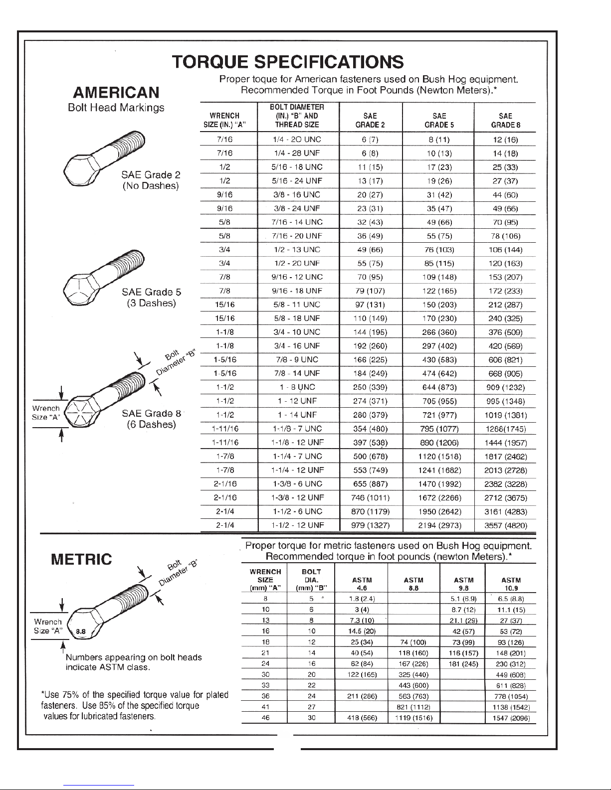
Torque Specifications - - - - - - - - - - - - - - - - - - - - - 21
1. Read the operator’s manual carefully and familiarize yourself with the proper use of your attachment. Do not allow
anyone who is not acquainted with the Safety Instructions to use your attachment.
2. Know the controls and how to stop quickly. READ THE OPERATOR’S MANUAL!
3. Do not allow children to operate the vehicle. Do not allow adults to operate it without proper instruction.
4. Be especially watchful of children and pets darting into the area while operating.
5. Keep your eyes and mind on your unit while mowing or operating your attachment. Don’t let others distract you.
6. Do not attempt to operate your unit or mower when not in the driver’s seat.
7. Always stop unit when emptying the container.
8. Stop unit, shut off deck attachment, set parking brake, shut off mower engine and remove spark plug wire before
removing clogs, removing or replacing hose, boot, blower cone, or performing any maintenance.
9. Mow across the face of slopes (not steeper than 10 degrees); never up and down the face.
10. It is recommended that the container be kept only half full when negotiating any slopes. Start mowing on slopes
when the container is empty.
11. Inspect your lawn and remove any foreign objects before mowing. Never deliberately run the mower across any
foreign object.
12. Wear ear protection if the noise level is offensive.
13. Wear eye protection to prevent debris from damaging your eyes.
2
Page 3
SAFETY
WARNING! NEVER operate the mower unless the discharge guard and either the deflector assembly or
the vacuum collector adapter are fastened securely in place.
WARNING! Do not work around the mower deck boot or the blower area until you are certain that the mower
blades and the blower impeller have stopped rotating.
WARNING! To avoid serious injury, perform maintenance on the vacuum collector; ONLY AFTER
STOPPING THE MOWER’S ENGINE AND WAITING FOR ALL MOVING PARTS TO COME TO A
COMPLETE STOP. Set the parking brake. Always remove the ignition key before beginning maintenance.
WARNING! For your own personal safety, ALWAYS mow ACROSS the face of slopes and NEVER UP
and DOWN the face. NEVER attempt to mow excessively steep slopes, and use caution when turning on any slope.
Safety Alert Symbol
This Safety Alert Symbol means: “ATTENTION! BECOME
ALERT! YOUR SAFETY IS INVOLVED!”
This symbol is used to call attention to safety precautions that
should be followed by the operator to avoid accidents. When
you see this symbol, carefully read the message that follows
and heed its advice. Failure to comply with safety precautions
could result in death or serious bodily injury.
!
Safety Signs
The signal words DANGER, WARNING, and CAUTION are used on the equipment safety signs. These words
are intended to alert the viewer to the existence and the degree of hazard seriousness.
This signal word indicates a potentially hazardous situation which, if not
DANGER
!
White letters on RED
WARNING
!
Black letters on ORANGE
CAUTION
!
Black letters on YELLOW
avoided, will result in death or serious injury.
This signal word indicates a potentially hazardous situation which, if not
avoided, could result in death or serious injury.
It may also be used to alert against unsafe practices.
This signal word indicates a potentially hazardous situation exist which, if
not avoided, will result in minor or moderate injury.
It may also be used to alert against unsafe practices.
3
Page 4

PECO LIMITED WARRANTY FOR NEW PRODUCTS
A. WHAT IS UNDER WARRANTY?
PECO extends the following warranties to the original purchaser of each new PECO consumer product subject
to the following limitations.
1. PRODUCT WARRANTY: Any part of any consumer product, which is defective in material or workmanship as
delivered to the purchaser will be repaired or replaced, as PECO elects, without charge for parts or labor, if the
defect appears within 12 months from the date of delivery of the product to the original purchaser.
ALL DEFECTIVE PARTS MUST BE RETURNED TO PECO FOR INSPECTION TO
DETERMINE VALIDITY OF WARRANTY CLAIMS. Freight and mailing will be borne by the customer.
2. PARTS REPLACED DURING WARRANTY: Any new PECO part which is furnished in performance of this
warranty and is defective in material or workmanship as delivered to the purchaser will be repaired or replaced,
as PECO elects, without charge if the defect appears within 90 days from the date of installation of such part or
before the expiration of the original warranty period, whichever is later.
B. SECURING WARRANTY ADJUSTMENTS.
Call PECO for Return Authorization. Damaged or broken parts other than engines or batteries, must be
returned to New PECO, Inc. 100 Airport Road, Arden, NC 28704 before any warranty adjustment can be
authorized. At the time of requesting warranty adjustment, the purchaser must present evidence of the date of
delivery of the product. The purchaser shall pay any charge for the product to and from Arden, NC.
C. ITEMS NOT COVERED BY PECO WARRANTY.
Engines and batteries attached to PECO products are covered under a separate warranty by the respective
manufacturer.
D. UNAPPROVED ALTERATION OR MODIFICATION.
All obligations of New PECO, Inc. under this warranty shall be terminated if products are altered or modified in
ways not approved by New PECO, Inc.
E. ACCIDENTS AND NORMAL MAINTENANCE.
The warranty covers only defective material and workmanship. It does not cover depreciation or damage
caused by normal wear, accident, improper use or abuse of products. The cost of normal maintenance and
normal replacement of service items such as belts, cutting blades, hoses, etc., which are not defective shall be
paid for by the purchaser.
F. NO REPRESENTATIONS ADDITIONAL WARRANTIES, DISCLAIMER.
Neither New PECO, Inc. nor any company affiliated with it makes any warranties, representations or promises
as to the quality of performance of its products other than those set forth herein. Except as described above,
New PECO, Inc. makes no other warranties AND SPECIFICALLY DISCLAIMS ANY AND ALL
IMPLIED WARRANTIES OF FITNESS AND MERCHANTABILITY.
G. ANY MACHINE USED FOR RENTAL PURPOSES ARE GUARANTEED FOR 45 DAYS FROM
DATE OF ORIGINAL SALE ONLY.
H. REMEDIED EXCLUSIVE.
The only remedies the purchaser has in connection with the breach or performance of any warranty on New
PECO, Inc. consumer products are set forth above. In no event will PECO be liable for special incidental or
consequential damages.
1. NO SERVICE CENTER WARRANTY.
The selling Service Center makes no warranty on his own on any item warranted by New PECO, Inc. unless he
delivers to purchaser a separate written warranty certificate specifically warranting the item. The dealer has no
authority to make any representation or promise on behalf of PECO or to modify the terms of this warranty in
any way.
4
Page 5
Section I
PRESS
PRESS
INTRODUCTION & DESCRIPTION
1-1 Introduction
Your grass collection system has been designed to give
you a low maintenance, simple, and effective way to
collect the grass clippings from your mower. This manual
is provided to give you the necessary instructions to
properly mount and operate the collection system on
your mower. Please read this manual thoroughly.
Understand what each control is for and how to use it.
Observe all safety decal precautions on the machine and
noted throughout the manual.
NOTE: All references made to right, left, front, rear, top
or bottom are as viewed from the normal operator’s
position on the mower.
1-2 Description
The grass collection system is designed for turf
maintenance where there is a need to collect the grass
clippings as the mower cuts the turf. It is also used for
picking up leaves in pre-season and post-season cleanup. The blower, mounted on the right side of the unit,
uses a belt and gearbox system from the engine PTO
shaft. Drive train protection comes through belt slippage.
The blower draws grass clippings from the discharge
area of the cutting deck back to the (2) - 3.3 cubic foot
collection bags P#(G0002) at the rear portion of the
mower frame. The operator can engage the blower with
a spring-lock engagement handle on the right side of the
unit. Once the bags are full with clippings, they can be
easily released for dumping.
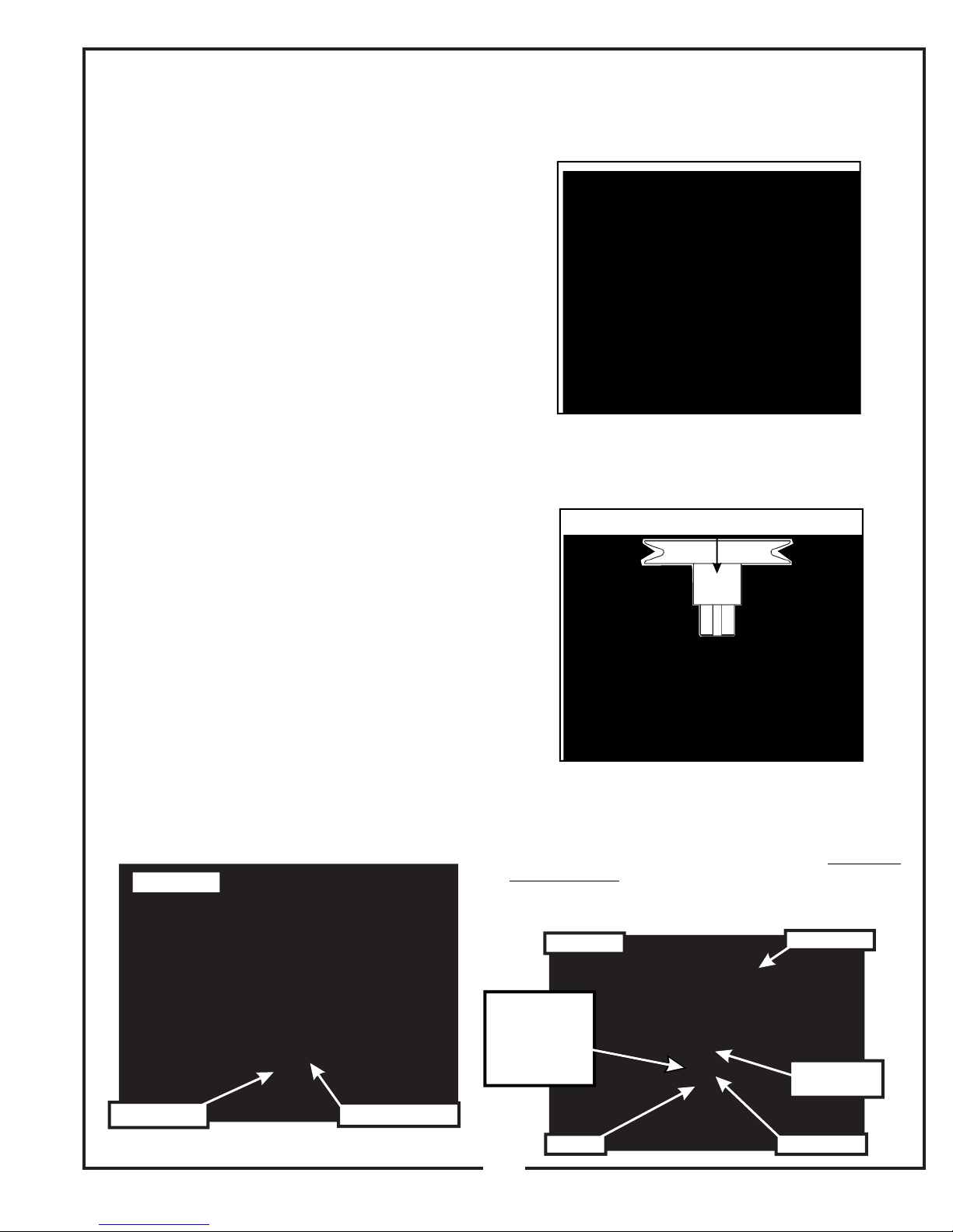
Remove the D-drive spacer using an arbor press or
equivalent. On removal, adjacent bearing OUTER race
must be supported or bearing damage may occur. Refer
to Figure 2-1b.
Figure 2-1b
The engine pulley assembly must be installed using an
arbor press or equivalent. Upon Installation, opposite
bearing inner race must be supported or bearing
damage may occur. Refer to Figure 2-1c.
Figure 2-1c
Section II
INSTALLATION FOR USE
2-1 Preparation Of Mower
From the underside of the engine, disconnect the wiring
harness attached to the electric clutch. Remove the bolt
and electric clutch from the mower. Refer to Figure 2-1a.
Figure 2-1a
Remove Bolt
Engine Bushing
Engine Pulley Installation
Use engine pulley assembly #2 P#(A0419). Fasten the
engine pulley to the electric clutch assembly using (1)
7/16” hi-collar lock washer P#( ) and (1) 7/16”-20 x K0140
3-3/4” HHCS P#(K0350) as shown in Figure 2-1d. The
added pulley will power the collection system. Torque the
bolt to 55 ft./lbs. Re-connect the wiring harness to the
electric clutch.
Figure 2-1d
Engine Pulley
Number Is
Stamped On
The Pulley
Bushing Here
Hex Bolt
Electric Clutch
Engine Pulley
Assembly
Lock Washer
5
Page 6
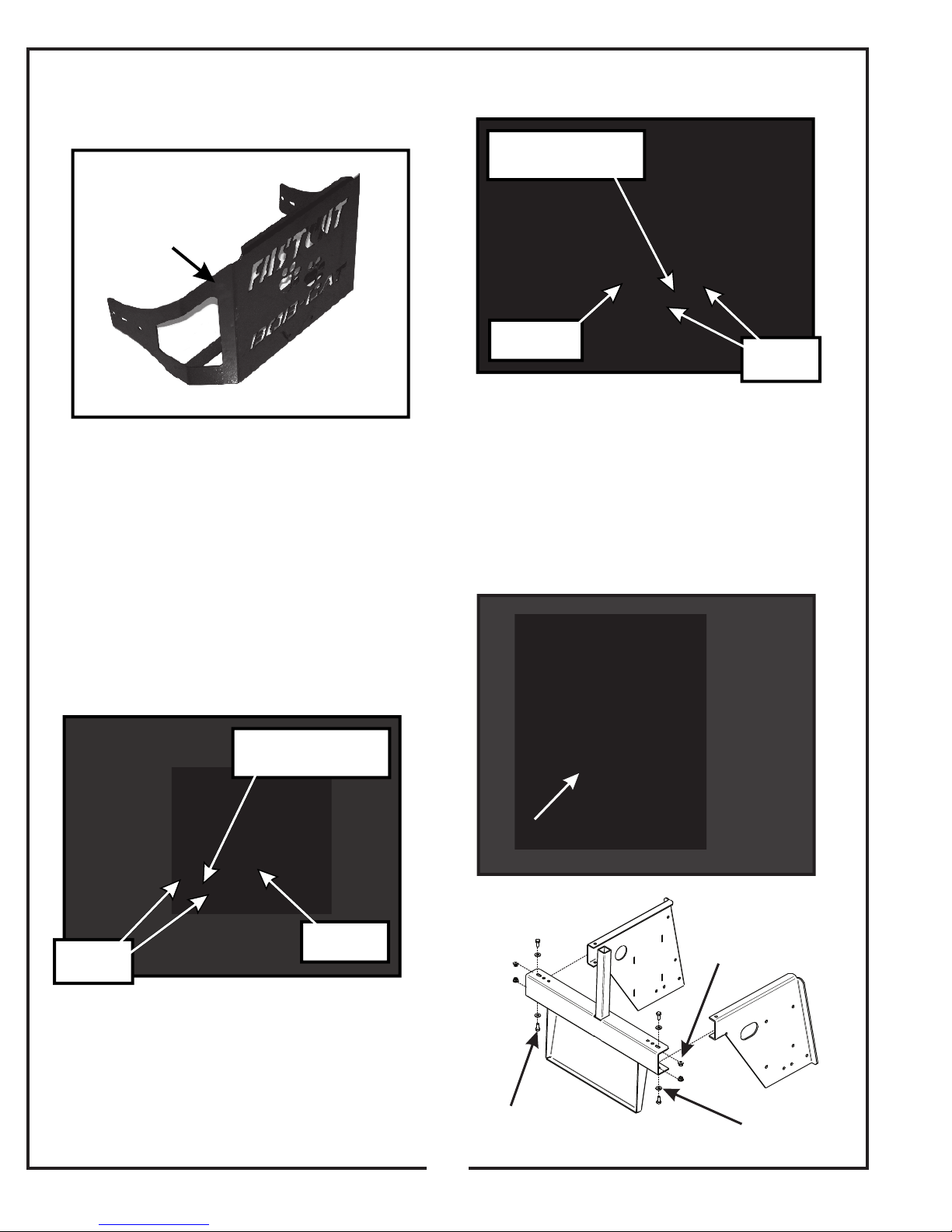
Remove the rear bumper shown in Figure 2-1e from the
mower frame. Keep the hardware for use later in the
installation.
Figure 2-1e
Remove
Rear Bumper
Figure 2-2b
(1) 3/8”-16 x 1” HHCS
(1) 3/8”-16 Locknut
Right Frame
Bracket
2-3 Lower Frame Assembly
Installation
Existing
Hardware
2-2 Left and Right Frame Bracket
Installation
With the rear bumper removed, position the left frame
bracket P#(B8138) as shown in Figure 2-2a. Secure the
left frame bracket to the mower frame using (1) 3/8”-16 x
1” HHCS P#(K1191), (1) 3/8”-16 nylon flange locknut
P#(K2038) and the existing hardware removed from the
rear bumper.
Figure 2-2a
(1) 3/8”-16 x 1” HHCS
(1) 3/8”-16 Locknut
Left Frame
Existing
Hardware
Bracket
Position the lower frame assembly P#(A1091) as shown
in Figure 2-3a. Secure the lower frame assembly to the
left and right frame brackets, using (4) 5/16”-18 x 3/4”
HHCS P#(K1153), (4) 1/4” flat washers P#(K0037) and
(4) 5/16”-18 nylon flange locknuts P#(K2516). Refer to
Figure 2-3b for reference.
Figure 2-3a
Lower Frame
Assembly
Figure 2-3b
5/16”-16
Locknut
With the rear bumper removed, position the right frame
bracket P#(B0746) as shown in Figure 2-2b. Secure the
left frame bracket to the mower frame using (1) 3/8”-16 x
1” HHCS P#(K1191), (1) 3/8”-16 nylon flange locknut
P#(K2038) and the existing hardware removed from the
rear bumper.
5/16”-18 x 3/4”
HHCS
6
1/4” Flat
Washer
Page 7
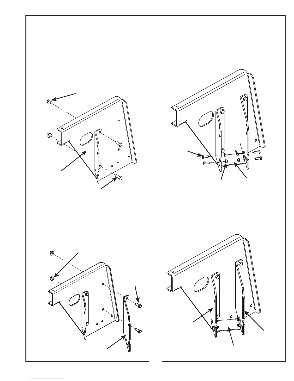
2-4 PTO Mount Plate Component
Installation
Fasten the left PTO mount plate P#(B0748) the right
frame bracket using (2) 3/8”-16 x 1” HHCS P#(K1191)
and (2) 3/8”-16 nylon flange locknuts P#(K2038). Do not
tighten the hardware. Refer to Figure 2-4a.
Insert the PTO stop plate P#(B0733) between the left
and right PTO mount plates as shown in Figure 2-4c.
Secure the PTO stop plate to the left and right PTO
mount plates using (4) 1/4”-20 x 3/4” HHCS P#(K1222)
and (4) 1/4”-20 nylon flange locknuts P#(K2014).
NOTE: Tighten all PTO mount plate component
hardware at this time.
Figure 2-4c
Figure 2-4a
3/8”-16
Locknut
Left PTO
Mount Plate
3/8”-16 x 1”
HHCS
Fasten the right PTO mount plate P#(B0747) to the right
frame bracket using (2) 3/8”-16 x 1” HHCS P#(K1191)
and (2) 3/8”-16 nylon flange locknuts P#(K2038). Do not
tighten the hardware. Refer to Figure 2-4b.
1/4”-20 x 3/4”
HHCS
1/4”-20
Locknut
Figure 2-4d shows the complete PTO mount plate
component assembly.
PTO Stop
Plate
Figure 2-4b
3/8”-16
Locknut
Right PTO
Mount Plate
Figure 2-4d
3/8”-16 x 1”
HHCS
Left PTO
Mount Plate
Right PTO
Mount Plate
PTO Stop
Plate
7
Page 8
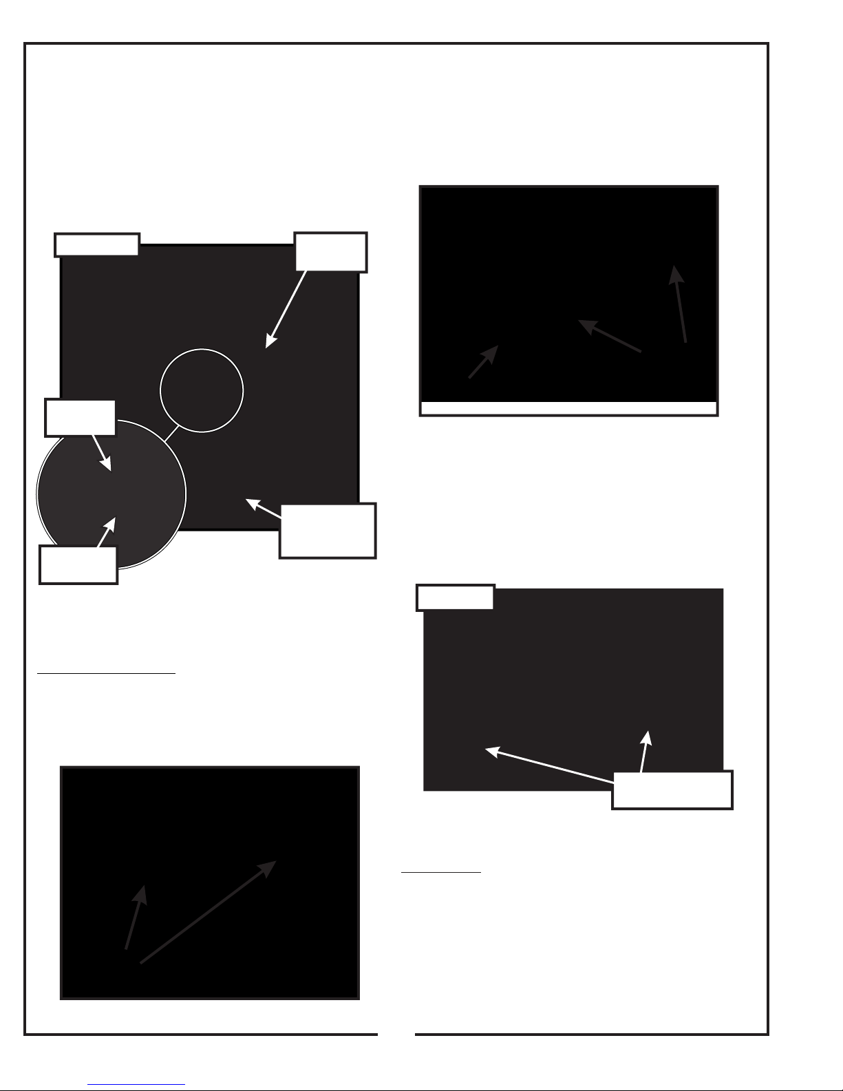
2-5 PTO Assembly Installation
Insert the PTO assembly P#(A1840) into the mounting
slots on the PTO mount plates, as shown in Figure 2-5.
Secure the PTO assembly with (1) PTO mount pin
P#(B0274) and (1) hair pin clip P#(K0086). Remove the
gear box pulley guard and hardware from the PTO
assembly in preparation for the belt installation.
Loosen the (2) 5/16”-18 x 3/4” HHCS P#(K1153) that
secure the gear box to the PTO assembly, as shown in
Figure 2-6b. Loosen the adjustment bolt (1) 3/8”-16 x 2”
hex bolt P#(K0348).
Figure 2-6b
Figure 2-5
PTO
Mount Pin
PTO Mount
Plate
PTO
Assembly
Remove
Pulley Guard
and Hardware
2-6 Belt Installation and Adjustment
Loosen
Hardware
Adjustment
Bolt
Slide the gearbox towards the mower until there is
enough clearance for the kevlar belt to slide over both
the engine and gearbox pulleys. Install the A55K kevlar
belt P#(M0248). Insert the PTO mount pin P#(B0274),
and secure the pin with (1) hair pin clip P#(K0086). Refer
to Figure 2-6c.
Figure 2-6c
Installation/Removal: With the pulley guard, PTO
mount pin and hair pin clip removed, loosen the (2)
5/16”-18 x 3/4” HHCS P#(K1153) that secure the gear
box to the PTO assembly. Refer to Figure 2-6a.
Figure 2-6a
Loosen
Hardware
Wrap Belt Around
Both Pulleys
Adjustment: To adjust the belt tension, turn the
adjustment bolt clockwise until there is 1” of deflection,
with 10-11lbs of pressure applied to the center of the
belt. When the belt has the proper tension, tighten the
(4) 5/16”-18 x 3/4” HHCS that secure the gear box to the
PTO assembly. Replace the pulley guard and hardware.
8
Page 9
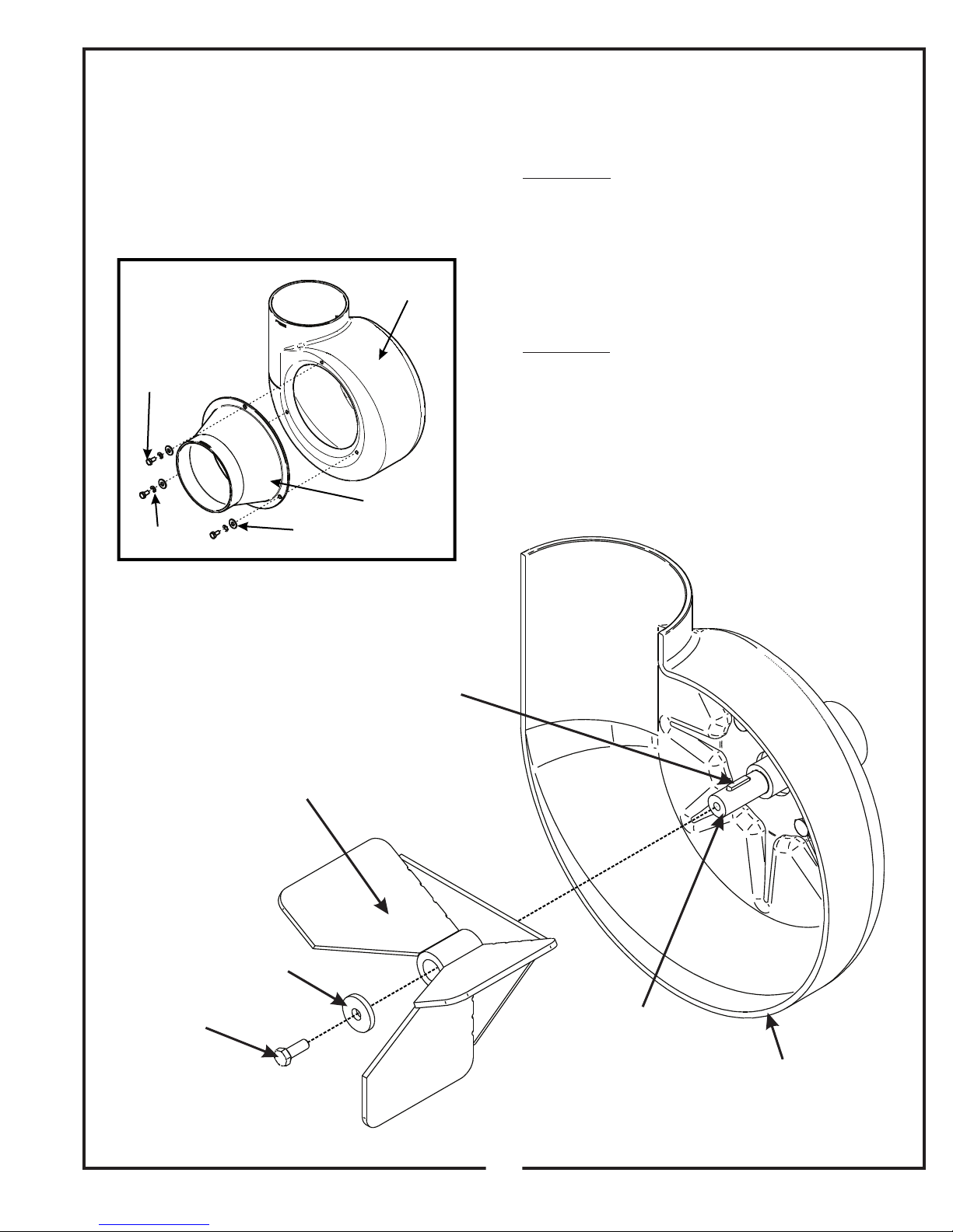
2-10 Blower Cone
Installation/Removal
Fasten the blower cone P#(V0016) to the blower
housing located on the PTO assembly. Use (3) 1/4”-20 x
3/4” HHCS P#(K1222), (3) 1/4” lock washers
P#(K0039), and (3) 1/4” flat washers P#(K0037) to
secure the blower cone to the blower housing. Refer to
Figure 2-10 for reference.
Figure 2-10
1/4”-20 x 3/4”
HHCS
1/4” Lock
Washer
1/4” Flat
Washer
Blower
Housing
Blower
Cone
2-8 Impeller Blade
Removal/Replacement
To Remove: To access the impeller blade, remove the
blower cone P#(V0016) and blower cone hardware from
the blower housing. Remove the 5/16”-24 x 7/8” left
hand thread hex bolt P#(K1171) and washer P#(K1446).
Insert (1) 1/2”-13 x 1” hex bolt into the threads on the
impeller blade. Tighten the hex bolt until the impeller
blade breaks free from the PTO shaft. Remove the
impeller blade assembly P#(A1839) from the PTO shaft.
Remove the key P#(J0254) from the PTO shaft.
To Replace: Insert the key P#(J0254) into the keyway
slot on the PTO shaft. Align the keyway slot on the
bushing of the impeller blade assembly with the key on
the PTO shaft and insert the impeller blade onto the
PTO shaft. Secure the impeller blade with (1) 5/16”-24 x
7/8” left hand thread hex bolt P#(K1171) and (1) washer
P#(K1446). Replace the blower cone P#(V0016) and
blower cone hardware. Refer to Figure 2-8 for reference.
Figure 2-8
.
J0254
Key
A1839
Impeller Blade
Assembly
K1446
K1171
PTO Shaft
V0016
Cross Section View of
Blower Housing
9
Page 10
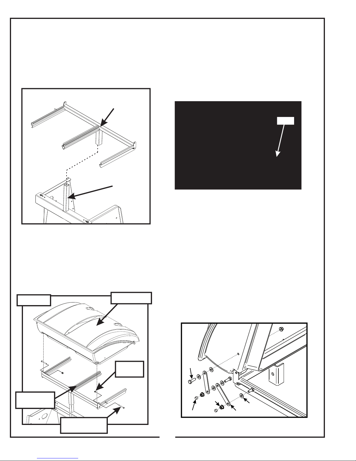
2-9 Upper Frame Assembly
Figure 2-9
Upper Frame
Assembly
Lower Frame
Assembly
Mount Tube
Installation
Lift the upper frame assembly P#(A0871) into position
above the lower frame assembly P#(A1091) as shown in
Figure 2-9. Slide the upper frame assembly onto the
lower frame assembly mount tube.
2-11 Inlet Installation
Insert the Inlet P#(V0019) into the hole on the top
assembly from the inside and then snap the inlet into
place. The inlet should pivot freely about the hole. Refer
to Figure 2-11.
Figure 2-11
Inlet
2-10 Top Assembly Installation
Lift the top assembly P#(A1028) into position above the
upper frame assembly. Secure the top assembly to the
upper frame assembly using (2) 5/16”-18 x 2-1/2”
P#(K0125) hex bolts and (2) 5/16”-16 nylon flange
locknuts P#(K2516). Refer to Figure 2-10 for reference.
Figure 2-10
Upper Frame
Assembly
5/16”-18 x 2-1/2”
Hex Bolt
Top Assembly
5/16”-18
Locknut
2-12 Hinge Kit Assembly Installation
Assemble the hinge kit as shown in Figure 2-12, using
(2) 5/16”-18 x 1” HHCS P#(K1154), (3) 5/16”-18 nylon
flange locknuts P#(K2516), (5) 1/4” flat washers
P#(K0037) and (2) swing arm brackets P#(ZT-0004).
Place (1) vinyl cap P#(J0289) on the end of the hex bolts
as shown in Figure 2-12. Leave the nuts loose enough to
allow fluid movement of the top when opening and
closing. When opened, the top should rest on the middle
joint of the hinge allowing it to remain up.
Figure 2-12
K1154
K2516
K0037
J0289
ZT-0004
10
Page 11
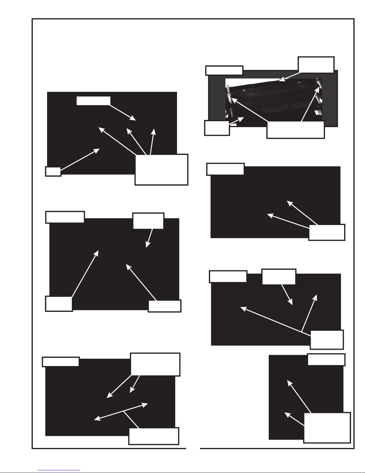
2-13 Boot To Mower Deck Installation
Raise the grass deflector on the mower deck. Fasten the
boot plate P#(B0750) to the boot P#(V1168) using (3)
5/16”-18 x 3/4” carriage bolts P#(K1142) and (3) 5/16”18 nyloc nuts P#(KK2516). Insert bolts from the inside of
the boot so that the threads are on the top outside of the
boot. This will help to prevent grass from collecting on
the bolts. Refer to Figure 2-13a.
Fasten the weight bracket P#(B1844) to the front frame
brace using (2) 3/8”-16 x 3-1/2” u-bolts P#(K0136) and
(4) 3/8”-16 nylon flange locknuts P#(K2038). Refer to
Figure 2-14b.
Front Frame
Figure 2-14b
Brace
Boot Plate
Boot
Secure the boot plate to the mower deck using (1) boot
rod P#(B0288) and (1) hair pin clip P#(K0099). Refer to
Figure 2-13b.
Figure 2-13b
Figure 2-13a
(3) 5/16”-18 x 3/4”
Carriage Bolts
(3) 5/16”-18 Nylon
Flange Locknuts
Insert
Boot Rod
Weight
Bracket
Insert (2) weight bars P#(B8146) into the weight bracket
as shown in Figure 2-14c.
Figure 2-14c
Secure the top weight bracket P#(B8145) to the weight
bracket using (2) 3/8”-16 nylon flange locknuts
P#(K2038). Refer to Figure 2-14d.
(2) 3/8”-16 U-Bolts
(4) 3/8”-16 Locknuts
Insert (2)
Weight Bars
Hair Pin
Clip
Boot Plate
2-14 Weight Kit Assembly Installation
Remove the owners manual case and hardware from the
foot rest. Remove the foot rest and hardware. Refer to
Figure 2-14a.
Figure 2-14a
Remove Owners
Manual Case
and Hardware
Remove Footrest
and Hardware
Figure 2-14d
Secure the owners
manual to the left
frame bracket using
(2) 1/4”-20 x 3/4”
HHCS P#(K1222) and
(2) 1/4”-20 nylon
flange locknuts
P#(K2014). Refer to
Figure 2-14e for
reference. Replace the
footrest and hardware.
Top Weight
Bracket
(2) 3/8”-16
Locknuts
Figure 2-14e
(2) 1/4”-20 x 3/4”
Hex Bolts
(2) 1/4”-20
Locknuts
11
Page 12
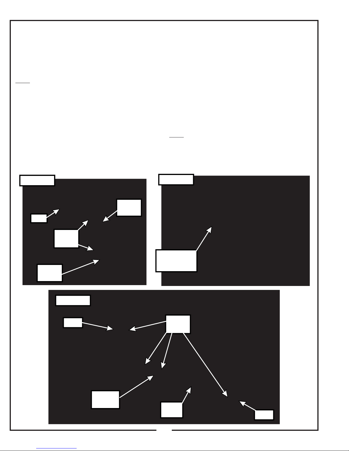
2-15 Length Of Hose Adjustment
The hoses in steps 2-16 and 2-17 must be cut to fit your
machine. Follow steps 2-16 and 2-17. do not cut the
hoses until you have tried to fit them on your machine.
Remember that the hoses have to be long enough to
adjust for the blower assembly’s movement as well as
allow for enough clamping surface between the inlet,
blower assembly, and the deck boot.
Note: The upper hose should no shorter than 22”.
2-16 Upper Hose Installation
Fasten the inlet to the plastic top by sliding the inlet from
the inside of the top to the outside and lock into place.
Slide a pre-assembled hose clamp P#(J0060) onto both
ends of the 6” upper hose (Figure 2-17). Then slide one
end of the 6” hose onto the inlet. Make sure there is
about a two-inch overlap between the hose end and the
container inlet. Proceed to slide the opposite end of the
6” hose onto the outlet of the blower assembly. See
(Figure 2-16) for details. Make sure both ends of the
hose are clearly attached to the inlet and the blower
assembly inlet. Tighten the hose clamps.
2-17 Lower Hose To Blower Cone
Installation
Slide a pre-assembled hose clamp P#(J0060) over both
ends of the lower hose. Then proceed to slide the lower
hose onto the blower cone. Tighten the hose clamp. The
assembly should look like Figure 2-18b.
2-18 Lower Hose To Boot Installation
Take the unattached end of the lower hose and slide it
over the circular end of the boot. Use the lower hose
clamp to secure the hose to the boot (Figure 2-18b). Tip:
Before securing clamp rotate hose counter-clockwise
(away from yourself) approximately 1” to aid in retaining
boot to mower deck.
Note: If the impeller blades continue to spin after the
PTO has been disengaged, make sure the bolt shown in
Figure 2-18a is not too tight. The bolt should be able to
spin freely.
Figure 2-16
Inlet
Blower
Outlet
Hose
Clamp
Figure 2-18b
Inlet
Figure 2-18a
Upper
Hose
Bolt Should Be
Loose Enough
To Spin Freely
Hose
Clamp
Blower
Cone
Lower
Hose
12
Boot
Page 13
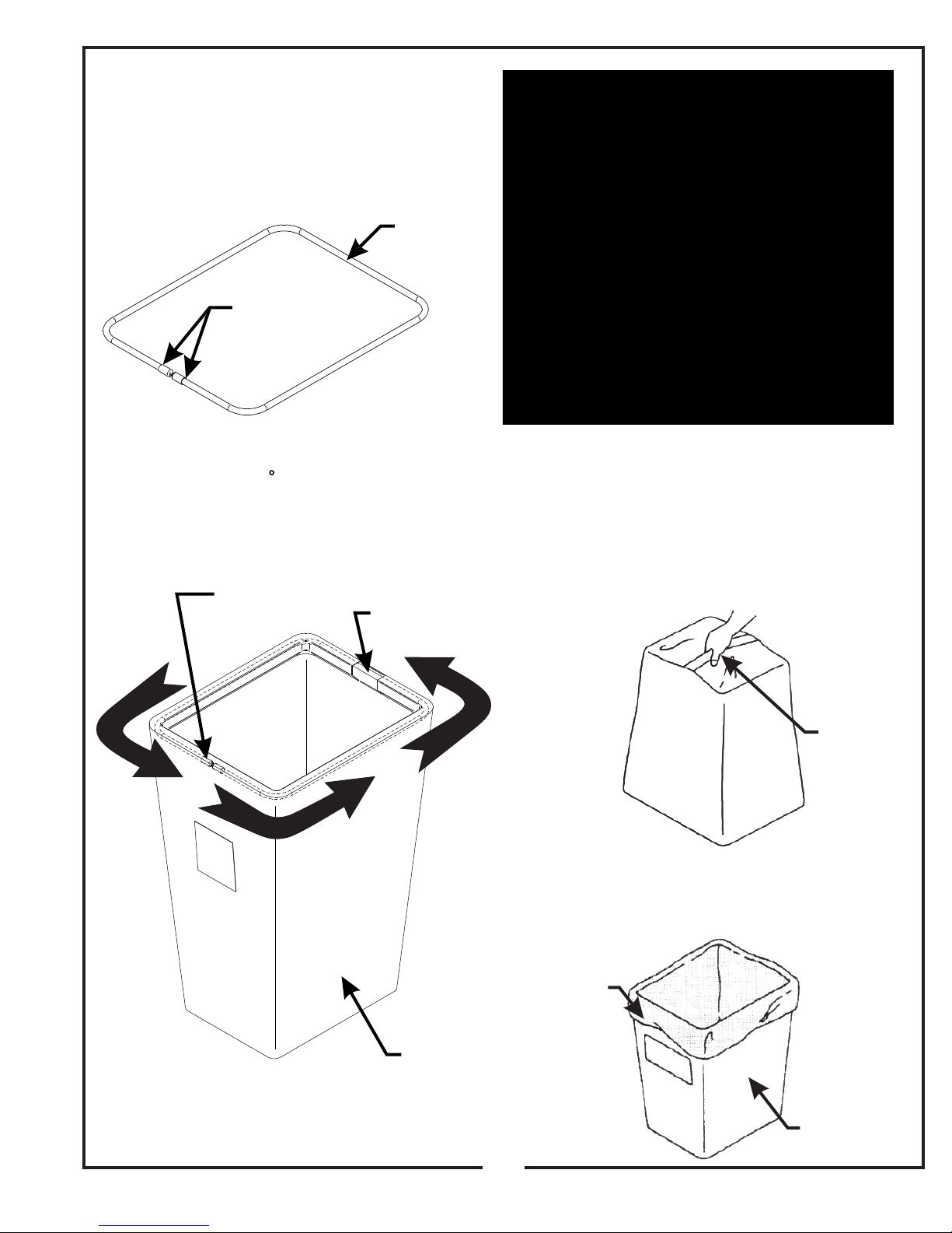
2-19 Installation/Removal Of
Collection Bags
IMPORTANT!
To prevent bag wear, install (2) red plastic end caps
P#(J0274), as shown in Figure 2-20a, on each bag ring
before installing bags.
Figure 2-19c
Plastic Top
Figure 2-20a
Red Plastic
End Caps
To install the bag onto the bag ring, place the seam
openings of the bag onto the bag ring openings and turn
the bag one full turn (360 ) so the plastic end caps are
located opposite to the opening in the bag (Figure 219b). Do this for each bag.
Figure 2-19b
Bag Ring End
Caps Opposite
of Bag Opening
Bag Ring
Bag Opening
Completed Bag
Installed
To empty the bag, first unlatch and lift top, next remove
the bag and bag ring by sliding rearward, then grasp the
loop on the bottom of the bag, and last turn it upside
down to empty the collected debris (Figure 2-19d).
Repeat for the other bag. Reinstall both bags, line with
plastic bags if desired, close the plastic top and reattach
the draw latches.
Figure 2-19d
Fasten Draw
-Latch Here
For Proper Unit
Transportation
Bag
Install the completed assemblies onto the support frame
and close the plastic top. Fasten the draw-latches to
hold the plastic top closed (Figure 2-19c).
Grasp Bag
Here
Plastic lawn and leaf bags, 33 gallon size, may be used
inside the cloth bags. Be sure to leave enough plastic
bag hanging over the frame so the plastic bags can be
twist tied before emptying (Figure 2-19e).
Figure 2-19e
Plastic Bag
Cloth Bag
13
Page 14

SECTION III
OPERATING INSTRUCTIONS
3-3 Disengagement Of The PTO
Assembly
3-1 General Safety
Only qualified people familiar with this operator’s manual
and the mower’s operator’s manual should operate this
machine.
3-2 Operation And Tips On Mowing
A. Perform BEFORE EACH USE the maintenance list
in
paragraph 4-1.
B. Start mower.
C. With the mower at high idle speed, engage the mower
deck.
D. While seated in the operator’s seat, pull the
engagement handle of the PTO assembly towards
the operator’s seat until the handle slides into
position in the retaining slot. With the PTO assembly
engaged, you can proceed to operate the control
levers of the mower.
NOTE: If the collection system does not appear to be
collecting the grass clippings, disengage the deck
and PTO assembly (Section 3-3), then, engage the
parking brake and turn the mower off. Check upper and
lower hoses for any clogs.
A. To disengage the PTO assembly, slide the
engagement handle out of the retaining slot and push
the engagement handle away from the operator’s seat.
WARNING: The PTO assembly blades will continue to
spin. DO NOT TOUCH the PTO assembly, pulleys, or
the belt until the tractor is turned off. DO NOT adjust the
belt tension until the mower is turned off. Refer to
section 2-6 of the manual.
3-4 Unloading The Collection System
NOTE: To determine when the collection bags are full,
follow the following steps:
A. Stop the forward movement of the mower.
B. Disengage the mower deck.
C. Disengage the PTO assembly.
D. Engage the parking brake.
E. Once the parking brake has been engaged, then and
only then, walk behind the mower and check the
collection bags by first unhooking the rubber strap
with S-hook that secures the plastic top, then lift the
plastic hood. Load in bags should not exceed the
height of the installed bag.
To obtain the maximum effectiveness from your
collection system, the tips listed below should be
followed:
* Watch your speed- Normal conditions will allow a
speed of up to approximately 4 mph, but thick, heavy
damp conditions will require reduced ground speed.
* Mow with sharp blades- A sharp blade cuts cleaner.
* Wet grass and leaves will decrease effectiveness and
will increase horsepower requirements.
* Mow at higher cutting heights- Remove and mulch no
more than 2” of grass length with each mowing.
(Experts recommend not cutting off more than 1/3 of
the grass blade length at any given time.)
* Mow twice, at different height settings, (high, then low),
if grass is extra tall.
* Remember that horsepower requirements will vary with
the mowing conditions such as type and height of turf
grass, moisture content, amount of leaves, whether the
terrain is flat or hilly, etc.
F. To remove the bags from the frame slide bags out and
turn bags over to deposit clippings.
G. Slide empty bags back onto the frame and secure
plastic top with the rubber strap with S-hook.
NOTE: Do not allow collection bags to become over-
filled as potential damage may occur to your
equipment. Also, be sure to clean the plastic top
screen as needed.
SECTION IV
MAINTENANCE
4-1 Maintenance Checklist
Before each use:
1. Check blades and spindles to be sure that no foreign
objects, such as wire or steel strapping bands, are
wrapped around them.
2. Inspect blades for wear. Replace if necessary. If it is
necessary to sharpen the blades, remove the blades
from the spindles before sharpening. DO NOT
sharpen blades while still attached to the mower.
14
Page 15
3. Make sure all shields are in place and in good
condition. Repair or replace any missing or damaged
shields.
4. Perform lubrication per paragraph 4-2.
4-2 Lubrication
NOTE: Use only white lithium based grease for
lubrication of the shaft on the blower assembly.
5. Listen for abnormal sounds, which might indicate
loose parts, damaged bearings, or other damage.
Correct any deficiency before continuing operation.
6. With the engine off, engage the blower assembly.
Check the belt tension and inspect the pulley belt for
cracks or tears.
7. Check for wear or deterioration of the upper or lower
hoses. If there are any portions of the hose that have
been torn or worn through, replace immediately.
After Each Use:
1. Clean all debris from machine especially from the
container, underneath the belt shields, and safety
decals. Replace any missing or illegible decals.
2. Inspect the unit for worn or damaged components.
Repair or replace before the next use. Any
replacement component installed during repair shall
include the component’s current safety decal specified
by the manufacturers to be affixed to the component.
3. Check belt for proper tension.
1. On initial use: Grease the fitting on the blower shaft.
2. Every 25 hours of use: Re-grease the grease fitting.
3. Every 200 hours of use: Check oil levels in gear box.
Oil in gear box should cover the gears. If not, fill using
an EP90 weight oil. 6oz. will fill the gear box from
empty.
SECTION V
PARTS AND SERVICE
5-1 Parts And Service Information
Collection system owners should record the name and
telephone number of their Service Center. Your Service
Center will be happy to supply replacement parts,
accessories, and do any service or repairs to your
collection system. If for any reason your Service Center
is unable to service your collection system or supply
replacement parts, contact PECO Inc. and include the
following information on the chart below.
THE SERIAL NUMBER PLATE
IS LOCATED ON THE TOP
ASSEMBLY
PECO
OUTDOOR POWER EQUIPMENT
Model Number
Serial Number
Arden, North Carolina 28704
WRITE THE MODEL AND
SERIAL NUMBER IN THE
BOX TO THE LEFT
FOR FUTURE REFERENCE.
Unit Model Number: _____________________________
Unit Engine Size: _____________________________
Unit Serial Number: _____________________________
Date of purchase: _____/_____/_________
Dealer/Distributor Name: ________________________________________
Address: _____________________________________ State: __________ Zip:__________
Phone Number: ____________________________
15
Page 16

16
Page 17
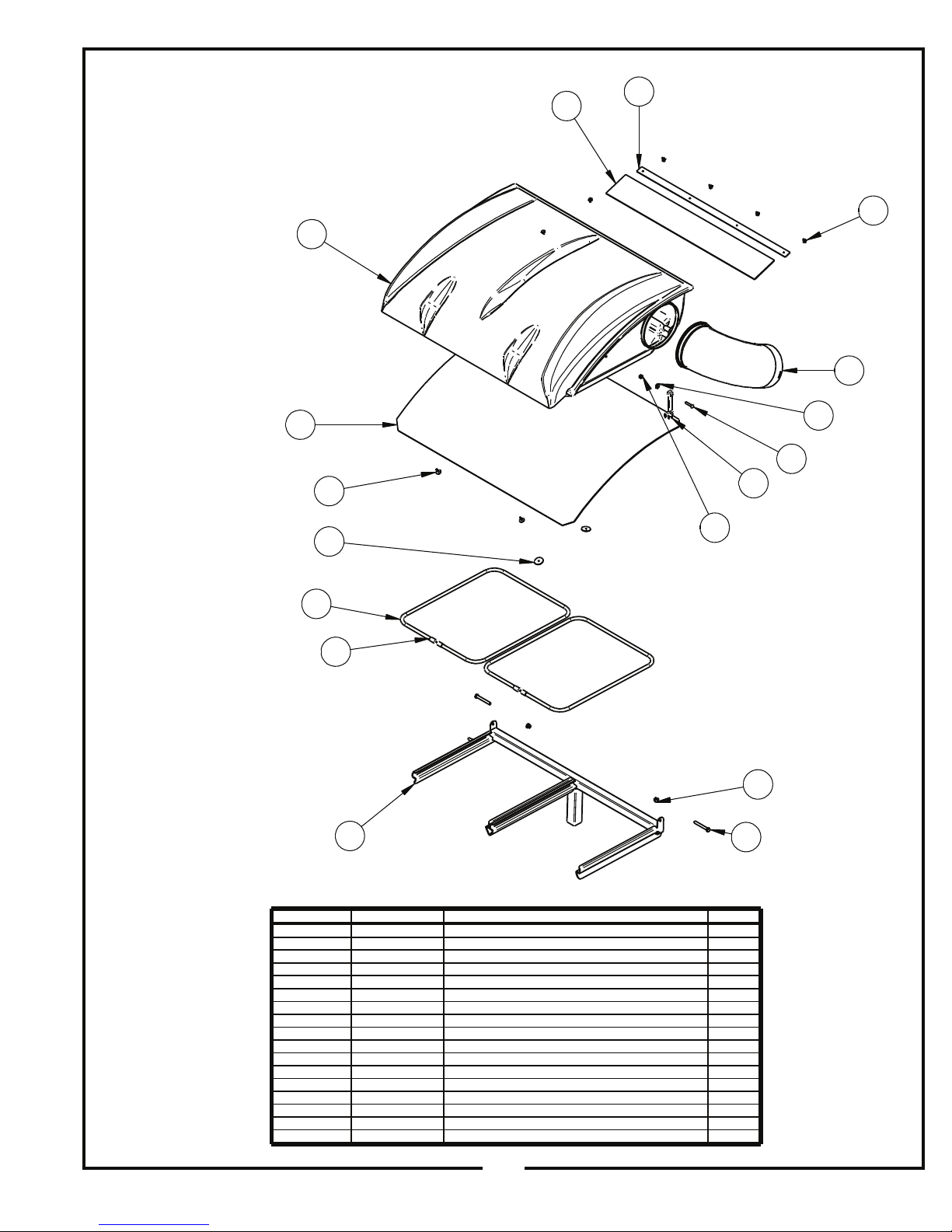
Item # Doc # Title Qty
1 A0871 2 BAG FRAME ASSY. 1
2 V0017 PRO 2 BAGGER TOP 1
3 V0018 Black Plastic Screen 1
4 J4009 SHORT RUBBER STRAP W/ S HOOK 1
5 K1030 1/4"-20 x 1-1/4" CARRIAGE BOLT 1
6 K0037 1/4" FLAT WASHER .75 OD x .314 ID x .060 T 1
7 k1128 1/4"-20 NYLOC NUT 1
8 K0062 3/16" x 1-1/2" FENDER WASHER, Z 2
9 K0114 BLACK PLASTIC RIVET 6
10 K1265 BLACK PANEL RETAINER 2
11 C0067 DUST GUARD BRACE 1
12 V1117 DUST GUARD 1
13 K0125 5/16"-18 x 2-1/2" ALL THREAD HHCS 2
14 K2516 5/16"-15 NYLON FLANGE LOCKNUT 2
15 B0227 BAG RING 2
16 j0274 BAG RING END CAP 4
17 V0019 INLET 1
1
15
11
16
4
6
8
9
13
5
7
10
14
2
3
17
12
A1028 TOP ASSEMBLY
A0871 UPPER FRAME ASSEMBLY
EXPLODED PARTS VIEW
17
Page 18
A2194 PTO BASE ASSEMBLY
EXPLODED PARTS VIEW
18
Page 19
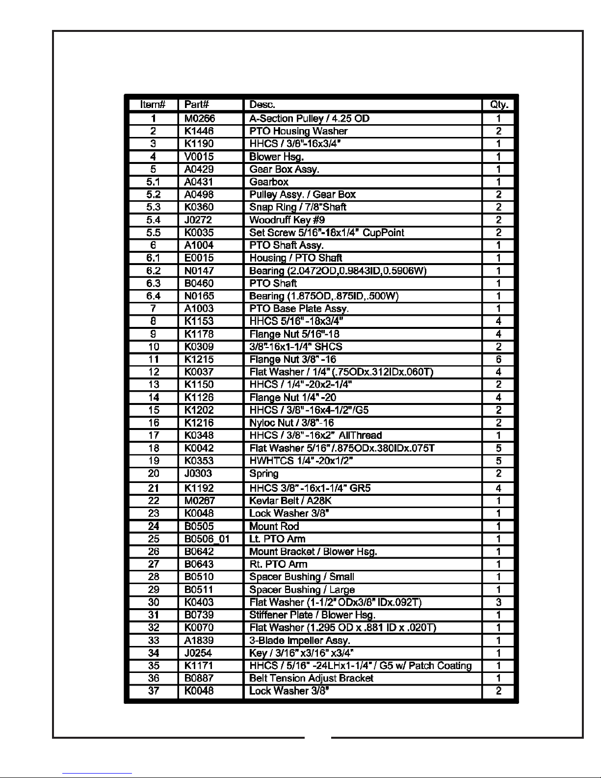
A2194 PTO BASE ASSEMBLY
EXPLODED PARTS VIEW DESCRIPTION
19
Page 20
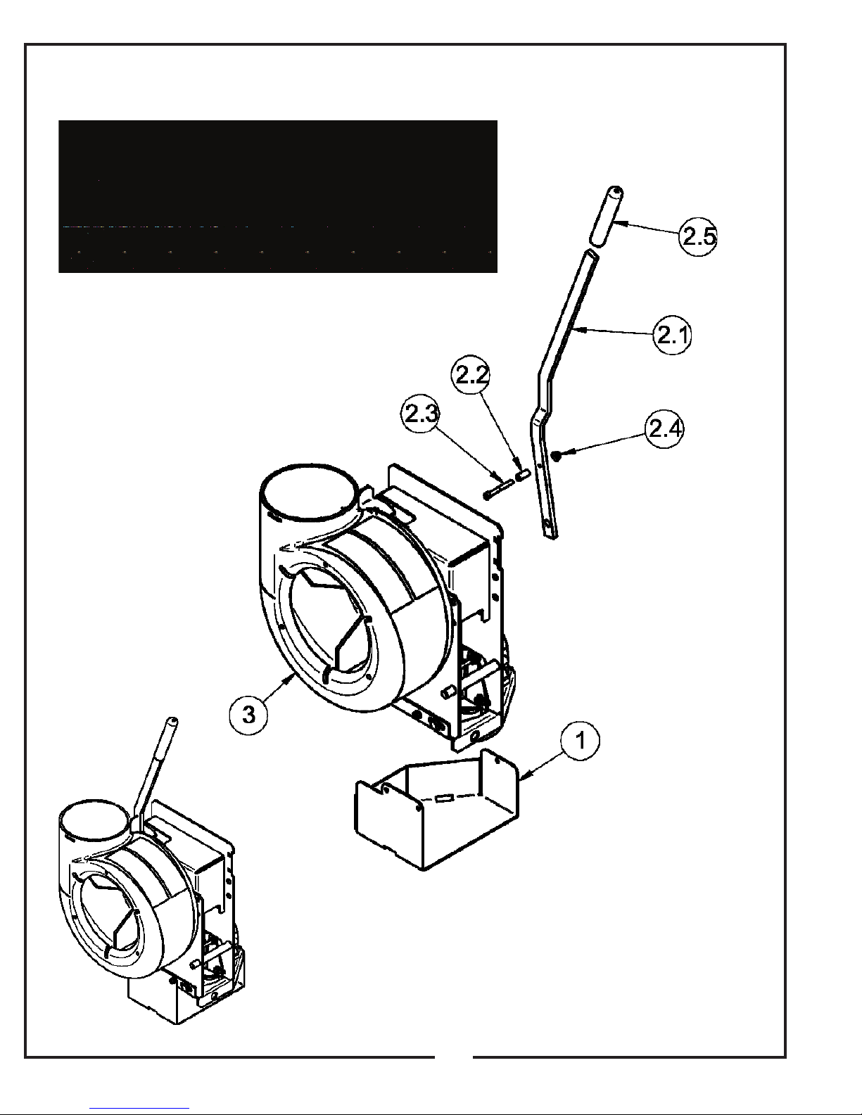
A1840 PTO ASSEMBLY
EXPLODED PARTS VIEW DESCRIPTION
20
Page 21
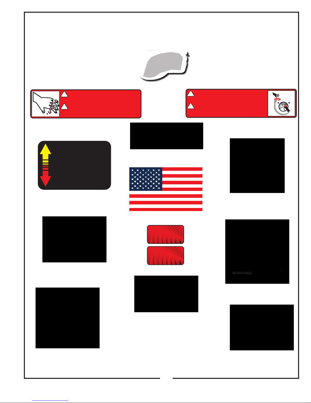
SAFETY DECALS
To promote safe operation, PECO Inc. supplies safety decals on all products manufactured. Damage can occur to
safety decals either through shipment, use or reconditioning. Contact your local Service Center for replacement decals.
R
PECOPECOPECOPECOPECOPECO
PECOPECOPECO
P
PP
P
PP
P
PP
P
PPP
Part #: R1070
DANGERDANGERDANGER
!
TO CLEAR D EBRIS WI TH BLOWER
PELIGROPELIGROPELIGRO
!
PARA LI NPIAR BASURA CON LA
R2007R2007R2007
HOJA EN MA RCHA!
NEVER US E HANDS
RUNN ING!
NUNCA US E MANOS
PECO Label
DANGERDANGERDANGER
!
FINGERS, HANDS, & BODY PARTS
PELIGROPELIGROPELIGRO
!
R2008R2008R2008
CAN BE SE VERED!
DEDOS, MA NOS Y PARTES D EL
CUERPO P UEDAN SER CORTAD OS!
ROTATING BLADES!
HOJA ROTANTE!
Part #: R2007
Never Use Hands Label
PUSH HANDLE
DISENGAGEDISENGAGEDISENGAGE
PULL HANDLE
ENGAGEENGAGEENGAGE
Part #: R1100
Engage-Disengage Label
Part #: R1054
Important Label
R1100
Part #: R4037
Warning: Hot Surface Label
MADE INMADE IN
MADE IN
AMERICAAMERICA
AMERICA
Part #: R1065
Made In America Label
Part #: R1057 - (2)
Part #: R2008
Rotating Blades Label
Part #: R1052
Small Warning: Turn Off Blower Label
Part #: R4015
Danger: Rotating Blades Label
Part #: R1069
Warning: Turn Off Blower Label
Part #: R1051
Warning: Hearing Protection Label
Part #: R4008
Caution: Rotating Blades Label
21
Page 22
22
Page 23

NOTES
Page 24

P
PPPP
ARDEN, NORTH CAROLINA 28704
(800) 438-5823 OR (828) 684-1234 FAX: (828) 684-0858
PECOPECO
PECOPECOPECO
10 WALDEN DRIVE
EMAIL: [email protected]
WEBSITE: www.lawnvac.com
 Loading...