

Page 1
Page 2
Intended to alert the user to the presence of uninsulated “dangerous voltage” within the product’s enclosure
A
A
CAUTION: Risk of electrical shock - DO NOT OPEN!
CAUTION: To reduce the risk of electric shock, do not remove cover. No user serviceable parts inside. Refer servicing to
qualified service personnel.
WARNING: To prevent electrical shock or fire hazard, do not expose this appliance to rain or moisture. Before using this
appliance, read the operating guide for further warnings.
that may be of sufficient magnitude to constitute a risk of electric shock to persons.
Intended to alert the user of the presence of important operating and maintenance (servicing) instructions in the
literature accompanying the product.
Contents
Quick Start
Introduction
Features ...........................................................................................................................................
About this Manual ..........................................................................................................................
Chapter I
The Front Panel ..............................................................................................................................
The Back Panel
Connection
The First Time You Turn It On (Reinitialization)
Adjusting The Global Input And Output Levels, and Global EQ
Chapter 2
Getting Started
Preview the Sounds from the Front Panel
Definitions and Abbreviations .....................................................................................................
Definitions
AbbreviationsL.............................................................................................................................
Chromatic Tuner ..........................................................................................................................
Chapter 3
Play Mode .....................................................................................................................................
Setting Up Your Programs
Performance Parameter Control .........................................................................................
Volume Control During Performance ..............................................................................
Chapter 4
Transmit and Receive Channels ..................................................................................................
MIDI Program Change and Bank Switching
MIDI Continuous Controllers
MIDI Volume Control
MIDI System Exclusive Remote Storage ...........................................................................
Loading Sets or Presets to their original locations
........................................................................................................................
........................................................................................................................
Setup
Diagrams
Overview
......................................................... ......................................................................
Editing Programs
Using MIDI
.............................................................................................................
..................................................................................................................
..................................................................................................................
.......................................................................
...........................................
...................................................................................................
..............................................................................................................................
.......................................................................
..................................................................................
..................................................................................................
...............................................................................................
..............................................................................
............................................................................................
..................................................................................................................
.....................................................................
..........
........
.........
.........
...........
..........
..........
4
6
6
7
8
8
10
11
16
16
17
17
17
17
17
18
19
20
20
20
21
21
22
22
22
23
23
24
25
ii
Table of Contents
Page 3
Loading Sets or Presets to new locations ...................................................................................
Remote Editing using MIDI System Exclusive ............................................................................
How to
Chapter 5
Initializing New Cartridges
Saving
Loading Presets from the
Cartridge Hattely
Tutorials
Editing and StoringaPreset .....................................................................................................
Program Mapping
Global Stuff:
SetupaContinuous Controller
RAM Cartridge
Presets on the
..........................................................................................................................
..........................................................................................................
C:trtridge
Cartridge
........................................................................................
..................................................................................................
......................................................................................................................
......................................................................................................................
Utility,
MIDI
and Controller Screens .................................................................. .32
Appendix A Individual Effects
Appendix
B
MIDI Implementation
Appendix C System Exclusive Format
Appendix D Remote Editing with SysEx
Specifications ..............................................................................................................................
......................................................................................
.............................................................................................
................................................................................
.........................................................................
..................................................................
..............................................................
25
25
26
27
27
27
27
27
28
28
29
A-I
B-l
C-l
D-l
1 )-c)
Table of Contents
Page 4
Quick Start
In an effort to make using our products easier to use, we have included this Quick Start section for all of you
who just hate to read manuals (and those of you that don’t need to read manuals). We hope this makes using
your new Peavey equipment a more enjoyable experience. As always, we appreciate any comments you have
on how to improve our products. (Hey, we’ll even listen to comments about the manual!)
v
To get started quickly
1.
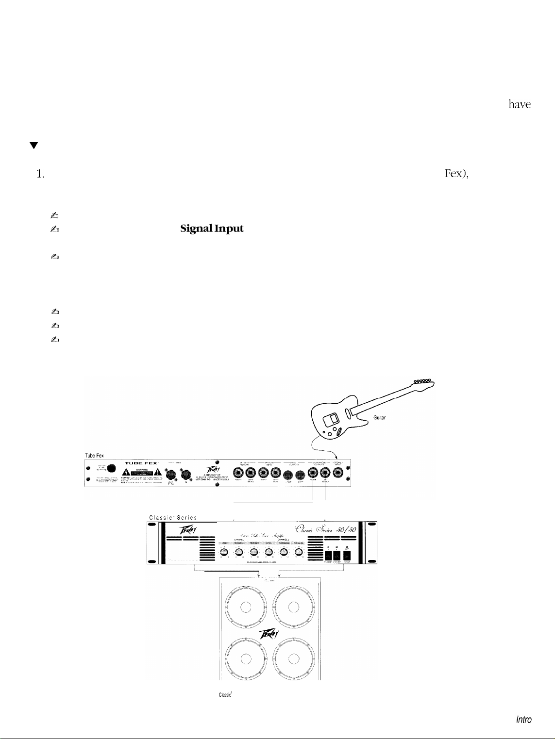
Well, the first thing you need to do (after opening the box and removing the Tube Fex), is to connect
the Tube Fex to your system configuration. Here are some things to check first:
&
Make sure your amplification system is turned off.
b
Plug your guitar into the
the one that is most convenient).
b
For mono operation, connect the Left/Mono audio output of the Tube Fex into the audio input of your
guitar amplifier or mono power amp. For stereo operation, connect the Left/Mono and Right audio
outputs of the Tube Fex into the left and right audio inputs of your power amp or into two individual
guitar amplifiers.
fi
Plug the Tube Fex into an electrical outlet and turn on.
a
Turn on your amplification system.
h
See the diagram below.
SignalInput
jack (there’s one on the front and rear of the Tube Fex, so pick
Classic, Series
50150
1 1
Classic’
41 OE
Page 5
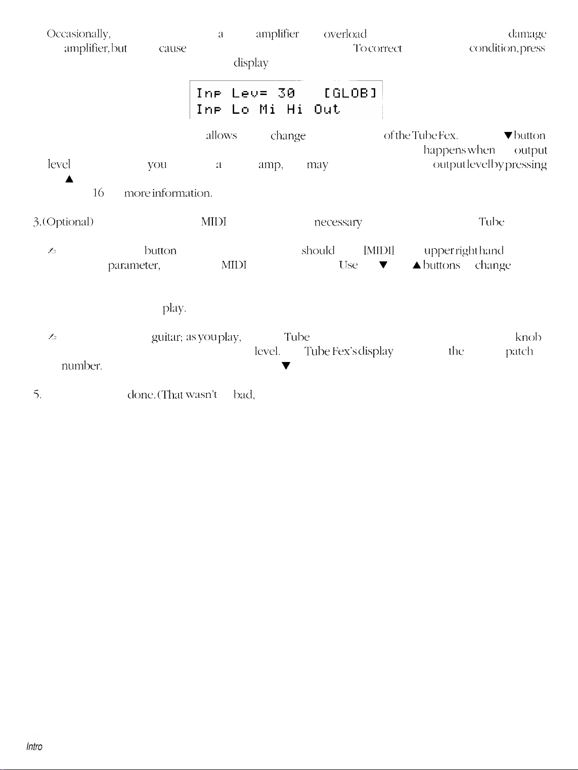
2.
Occasiordy,
the
:tmplifier, lxrt
plugging directly into ;I guitar
it will cause unwanted distortion of the signal. To cc
the Global button until the following
:mplifier
display
may
appears:
overlod
the input slightly. This won’t
m-ect
this overload cc
mdition, ptws
clmxgc
Move the cursor under
Out.
This
~dlows
you to change the output level
ofthe Tulx Fcx.
until you find a level where the unwanted distortion disappears (this usually
le\d is around 7). If
the A button. See the section titled
on page 16 for
3.
(Optiond) To send and receive
./J
Press the
Global
The first parxneter, RC, sets the
you
x-e using 21 power
mip,
Adjusting the Global Input and Output Levels and Global EQ,
more inforniation.
MIDI
information it is
button several times (the display
MIDI
Receive channel. IJse the V and A
you
may
want to increase the
necesmy
shodd
to properly set up the
show
[MIDI]
the desired channel.
4. Okay. Now it’s time to
.e
Start playing your
clockwise until you reach the desired
numl->er.
5.
That’s it, you’re
To select a different patch, use the 7 and A buttons.
done. (That wxm’t
pl;ly.
g:uitar: as
you
play,
turn the Tube Fex’s
level.
The Tube
so
1~~1,
was it?)
Post Gain/Global Output Level
Vex’s display
h;ippt’ns when
outp~rt led by prc’ssing
in the upper
buttons
will show
Press the v lxltton
the
(mtput
Tc11x
Fex.
rigllt
hmcl corner>.
to
dunge
this to
knoll
tlje
current
p:ltcyh
Page 6
Introduction
(obligatory
Congratulations and thank you for purchasing the Peavey Tube
dual
12AIY7
The Tube Fex is two different signal processors in one unit. First, it is a dual-tube guitar preamp that delivers
fat tone, crisp, clean settings, and thick distortions with a fully programmable, highly user-friendly interface.
In fact, it is probably the most user-friendly MIDI-programmable tube preamp in the industry today. The gain
and tone knobs are actually data encoders. Each is surrounded by eleven, easy-to-see
knob’s setting. As each new program is called up, different
settings for the new program. You can change gain and tone settings by turning individual data encoders
knobs, and when you find the setting you like, simply press the store button and the changes will be saved
to the program.
The Tube Fex has 37 effects types available, including eight reverbs, three delays, chorus, flange, exciter, coil
tap, auto pan, noise gate, stereo splitter, dual pitch shifters, tube and digital distortions, hum filter, envelope
filter, stereo tremolo, compression, selectable front panel tone controls, four internal EQs, speaker simulator,
and fx loop. Effects algorithms are completely user-definable and true-stereo effects chains can be written.
The tube preamp can be placed anywhere in the effects chain. Even the digital distortion can be used
simultaneously with the tube distortion to create unique stereo effects.
The Tube Fex features mono inputs and mono/stereo outputs.
Opening9
tube guitar preamp with
Fex’“‘.
The Tube Fex is a MIDI programmable
24-bit
digital stereo effects processing in a one-rack-space unit.
LEDs
LEDs
around each knob light up, indicating the
that indicate each
FEATURES
Up to seven simultaneous effects
MIDI-programmable dual
MIDI-programmable digital stereo effects processor with over 30 effect types
User-definable effects algorithms
Selectable front panel tone controls, 3 internal graphic
Stereo effects chains are fully independent
Dual pitch shifters
Progralnmdble
128 user programs, 128 factory presets
RA.M
card slot for storing or adding
Preamp
11 easy-to-see
Programmable
Programmable global room EQ and pre and post gain levels
On-board chromatic tuner with programmable mute
Mono inputs (front and rear panel), mono/stereo outputs, stereo balanced direct outputs
Internal power supply
Single rack space
Programmable FX loop with stereo sends and returns
Assignable clip LED
Programmable speaker simulator
and more
12Ax7
master output level on each effect
gain and tone knobs are data encoders that allow changes in knob settings to be stored
LEDs
around each knob indicate control position
4-position
tube mode adds tube gain stages and utilizes passive and active EQs
tube preamp
EQs,
128
additional programs and presets
or a 4-band parametric EQ
Intro
Page 7
ABOUT
THIS MANUAL
Still reading? We consider that very high praise indeed!
they’d rather try and figure things out themselves, and that would be unfortunate because in this manual we
try to provide you with the information necessary to make the most use of your new equipment. Not just
technical stuff, but real everyday type
Have Fun.
This manual is separated into several distinct chapters.
Chapter 1, Setup, will show you how to setup the Tube Fex in several common application scenarios.
Chapter 2, Overview, provides an overview of the Tube Fex ranging from a list of the abbreviations to the
user interface. This chapter is a must, don’t miss it.
Chapter 3, Editing Programs, provides an overview of the effect structure, how to create a
chain, editing individual effects parameters, storing your program, and more.
too technical. You should probably check this out.
Chapter 4, Using MIDI, shows you how to setup the Tube Fex to allow for sending and
data, how to load programs into new (and their original) locations, storing program via
should definitely read this chapter, if for no other reason
channels, and how to load programs.
infornTation
LJsually
that will make using the Tube
people don’t want to bother reading manuals,
LJseful
tlyan
to find out how to set the
F:ex
much more fulfilling.
custom
information that’s not
receiving
MIDI,
and more. You
MI111
send
of
and rcccive
effects
MIDI
Chapter 5, RAM
Useful only if you intend to store programs to cartridge.
Appendix A,
than is provided in Chapter 3. This chapter lists
This section provides lots of information that the typical user probably doesn’t need.
Appendix B, MIDI Implementation,
Appendix C, System Exclusive Format. At-e you
command
Appendix D, Remote Editing with
the Tube Fex. Again, this is vely technical so advanced users will
Cartridge,
IndividualEffects,
format for the Tube Fex. This is very technical, advanced users will
deals with saving your programs in memoty and storing them to ;I RAM cartridge
is ;I reference section for those who want more information about the effects
each
effect, its parameters
is a chart that summarizes the MIDI support provided by the
sure you want to go
SysEx,
shows you how to use system exclusive messages to program
, and the range for each parameter.
’ ‘l’his
hcrc!
I
probabl)
gain the most
details the
gain tlic most
systcrii
from
from this.
TLI\X Fex.
exclusive
this.
Intro
Page 8
Chapter 1 Setup
TU6EFEX’”
1
LlhllTS FOR A CL ASS R COMPUTlNCl
0
0
0
C3
0 GLOE AL
120 VAC
60 Hz
60 WATTS
THIS UNIT
COMPLIES
DEVICE PURbUANTTO
J
OF PART 15 OF FCC
TUBE GUI-I-AR
QQQ
0
0
0 0
0 0
~-
PRE
l;AIN
INPUT
DUAL 12AX7 MIDI TUBE PREAMP
2
WITH
THE
SUBPART
HU, ES
--BP.531 --
LEV
3
TU6E
WARNING:
SHOCK DO NOT EXPOSE THIS EQUIPMENT TO RAIN OR
MOISTURE
AVIS:
RISQUE DE CHOC ELECTRIOUE-NE PAS OUVRIR
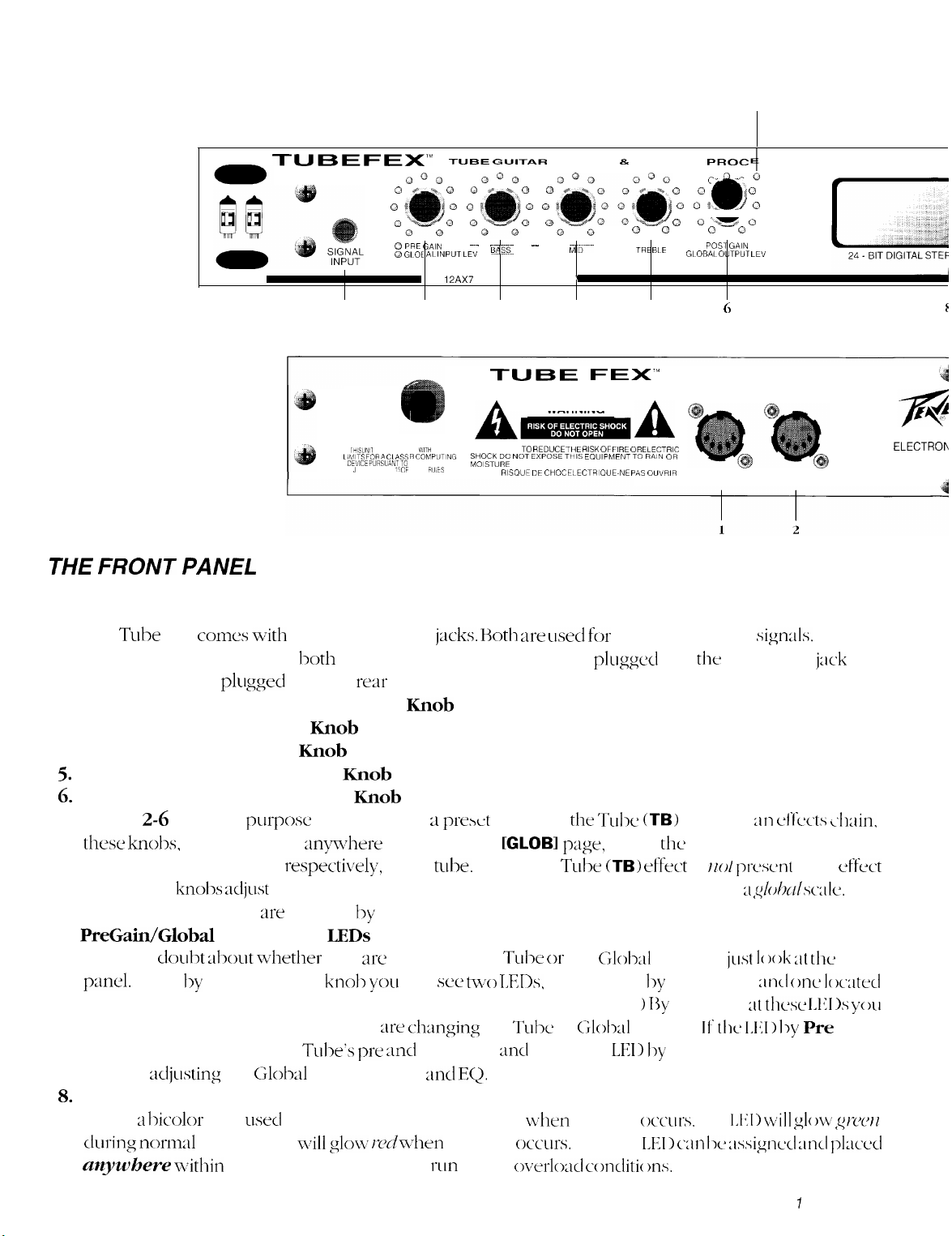
THE FRONT PANEL
1. Signal Input
The Tube Fex
instrument is plugged into lxd~ the front and rear jacks, the one
override the one
2. Preamp Pre Gain/Global Input Level Knob
3. Preamp Bass/Global Bass Knob
4. Preamp Mid/Global Mid Knob
5.
Preamp Treble/Global Treble
6.
Post Gain/Global Output Level Knob
Knobs
2-6
these knolx,
Treble, and Post Gain, respcxtivdy, of the
chain, these knobs
means that all presets
7.
PreGain/Global
When in
pand. Right by the Pre Gain knob
by Global Input Level.
can instantly determine whether you
is lit, you are adjusting the
you x-e
8.
Assignable Active Clip LED
This is ;I
l%color
during norinal
anywhere u+thin
conxs with
plu
two Signal Input
aged into the
rear
input jack.
Knob
are dual
purpose
knobs. When 21
when changed x-qwher~ other than the
adjust
the
Input level, Bass, Mid, Treble,
are
affected by these settings.
Input Level
doul,t about whether
LEDs
you
arc
adjusting the Tube or the
you
will sw
(Notice that only one is lit at any
x-e changing
adjusting
LED
activity and
the
Tube’s pre and
Globd
usd
input, output md
to indicate normal activity and
will glow rwln-lien
post
the effects chain to help
jacks. Hoth are used for
prext
contains
[GLOBI
tulx.
When The
two LEDs,
the
gain
and
EQ.
clipping
rim
down
PREAMP 8. EFFECTS
0
TREBLE
0
5
Q0 ,P
0
0
GLOBAL OLJTPUT LEV
0
8
0
Q
0 0
WARNING
MD--
’
4
FE><‘”
A
TO REDUCE THE RISK OF FIRE OR ELECTRIC
instrument level
plugged
that Tulx
page,
adjust
Tulx
(TB)
and
Output level on ;I
GloM
one located by Pre Gain
given time. >
T&e
or
Glolx11
EQ.
If
the
when
clipping
occ’~irs.
The clip
oc~rloacl conditi~ ms.
into
(TB)
effect in an
the
Pre Gain, Bass, Mid,
effect is
settings,
13~
glancing 2t
settings. If
LET) I>y
Global Input Level
occ~~rs.
LEI> can Ix zi,signccl mcl plxwl
PROC
QOQ~
0% oli
o~%.&,P
0 0
POST GAIN
OUT/
THRU
SSOR
Q
‘W
0
0
6
MIDI
sigrxlls.
the
front input
HO/
prcscmt
https://manualmachine.com/d~rzlsc;llc.
just 1~ )ok at the
zncl
thcs~
the 1,111) by Pre
The
I,[<1 > \/2rill
CLIP
PEAVEY
IN
MERIDIAN, MS MA
If an
jack
will
ef‘fccts ~~lmin,
in an cffwt
This
front
one
Iowed
IAl<1 1s
you
Gain
is lit,
glow
g/-c~jt~
A PRODUCT
ELECTROh
f
Chapter
7
Setup
Page 9
A I
PLAY
11
12 13 14 15 16
-
EDIT
ON
CORP.
J U.S.A
EFFECTS- _________ EFFECTS-
RETURN SEND
MONO MONO
\
>f
3
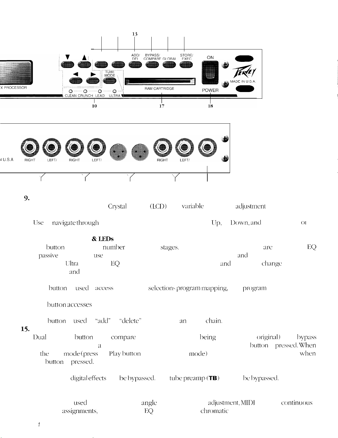
9.
Display window
20 character x 2 line Liquid
t
4
_________ DIRECT
OUTPUTS OUTPUTS INPUT
RIGHT LEFT
Crystal
_________
\
f
5
Display
______
UNBALANCED- ~ SIGNAL
MONO
-.
;f
6
(LCD)
with
varialk
I
I
7
view angle
10. Arrow (Direction) Buttons
LJse
to
navi@e through
the menus on the display: Left, Right, IJp, or
decrement selected values.
11. Tube Mode Button &
This
is
pmsive
tube. When
Body, Edge,
12.
Play Button
This
hutton
increases the
and
IJltra
button
is
you
:tnd
usecl
is
Shift,
LEDs
will
LW
used,
respectively.
to
;~ccess
nundm-
Pregain, Pad, Postgain, Bass, Middle, Treble, md Presence
the
of tube gain
EQ
is active and
the preset
stag:es.
Bass, Middle, Treble, md Presence
selection~~
When Clean, Crunch, or Lead XC selected the
progmn
mapping,
13. Edit Button
This button
3ccesses
the editing functions for constructing new presets or editing existing ones.
14. Add/Del Button
This
button
15.
Bypass/Compare Button
L>ual
function
is
LMX~
button
to
used to
‘*dd”
or
bbclelet&’
coqm-e
effects from m effect
two presets (the one
ch:lin.
king
edited to the origiml) or to
the unit. When editing ;I preset the Compare function is accessed when this
in
that
this
play mock
lmtton
is
iprt-‘ss
prmml.
the
Pl;ly tmtton
to enter the play
mock>
the Bypass function is accessed
djustment
Down, md
and
pr0gt-m~
htton
for easy visibility.
to increment
01
for editing the
c-hange
to;
Bottom,
volume.
byp:lss
is
pressttcl.
When
wkn
EQ
Note: Only the
cli,git:ll effects
16. Global Button
This button is
controller
Chapter
1
:tssignnlents,
Setup
can be k~yp~sd. The
W+X~
to access the view
global gain and EQ settings and the
tube
mglc
adjustment, gain
premq~
(TB)
cannot 1~
djustment, MIDI
chronlatic
tuner.
I~yp;lssecl.
settings, umtinuous
Page 10
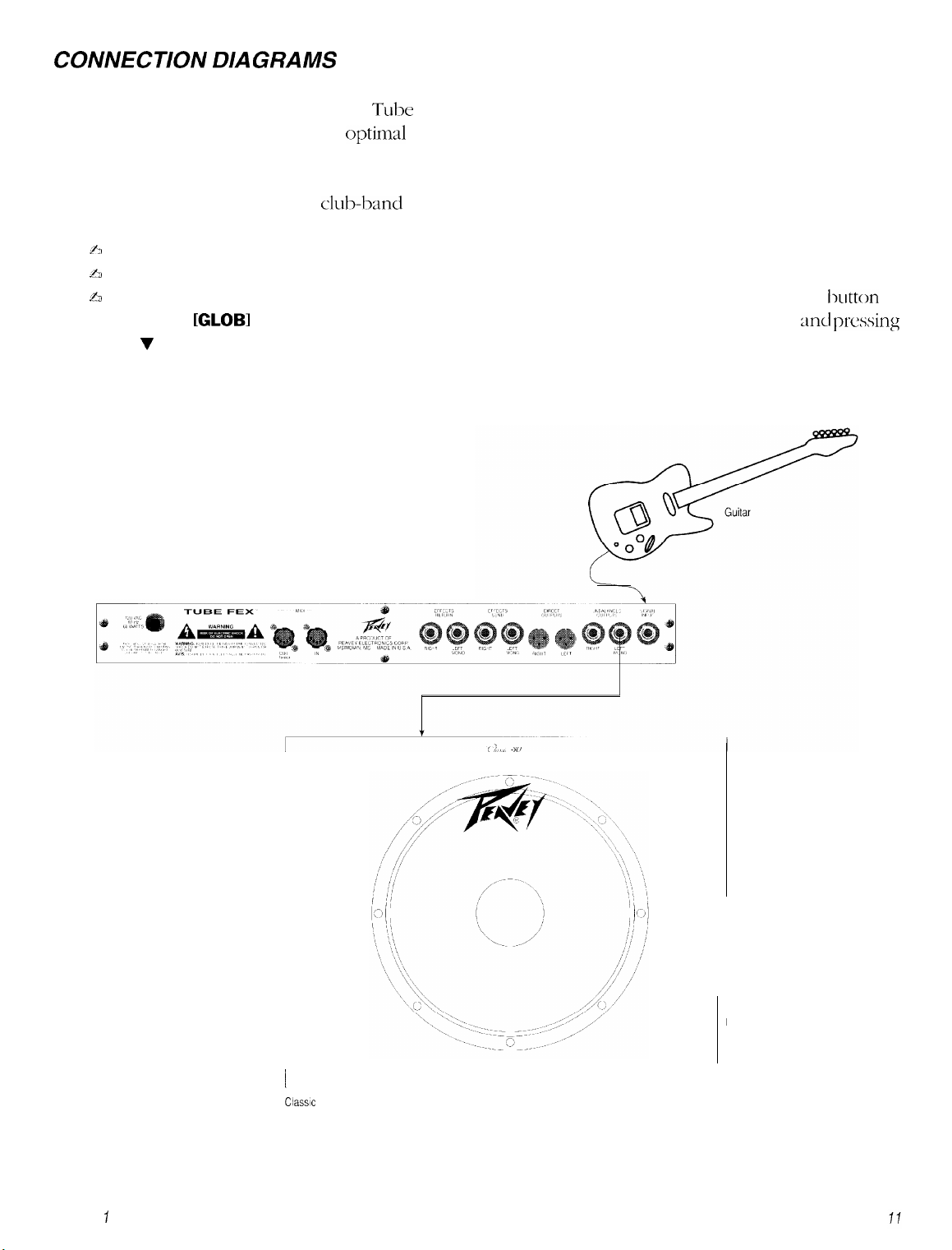
COAHVECTION DIAGRAMS
There are many ways to connect the Tube Fex into your instrument system. Shown here are some
recommended hookups to give you optimd performance in some common situations.
1. Using the Tube Fex direct into a mono guitar amp.
This is the basic setup many
~2
Connect your guitar to the Signal Input jack on the Tube Fex.
b
Connect the Left/Mono Unbalanced audio output to the input of the guitar amp.
A
If the signal from the Tube Fex overloads the input of your guitar amp, press the Global
access the
[GLOBI
display and adjust the output level by placing the cursor under Out
the v button until the overload condition disappears.
clubband
guitarists use. To hook up:
button
to
and pressing
Tube Fex
Chapter ISetup
Classic 30
Page 11
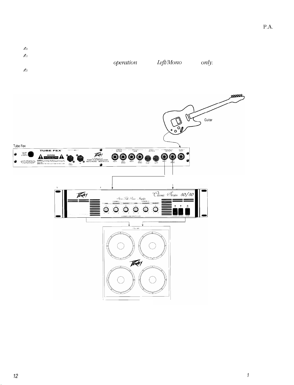
2. Using the Tube Fex with a separate amplifier and speakers.
This is a typical home, practice, or stage setup where the Tube Fex is not directly connected into the
system, but played through a separate amplifier and speakers. To hook up:
ti
Connect your guitar to the Signal Input jack on the Tube Fex.
$3
Connect the Left/Mono and Right Unbalanced Outputs (stereo) to the Left and Right Inputs of the
amplifier, respectively. For mono opemtioa use the
ti
If you haven’t already done so, connect the Left and Right Outputs of the amplifier to speakers.
LeJ?t/Mono
Output
only.
PA.
Classic” Series 50150
Classic’ 41 OE
72
Chapter
7
Setup
Page 12
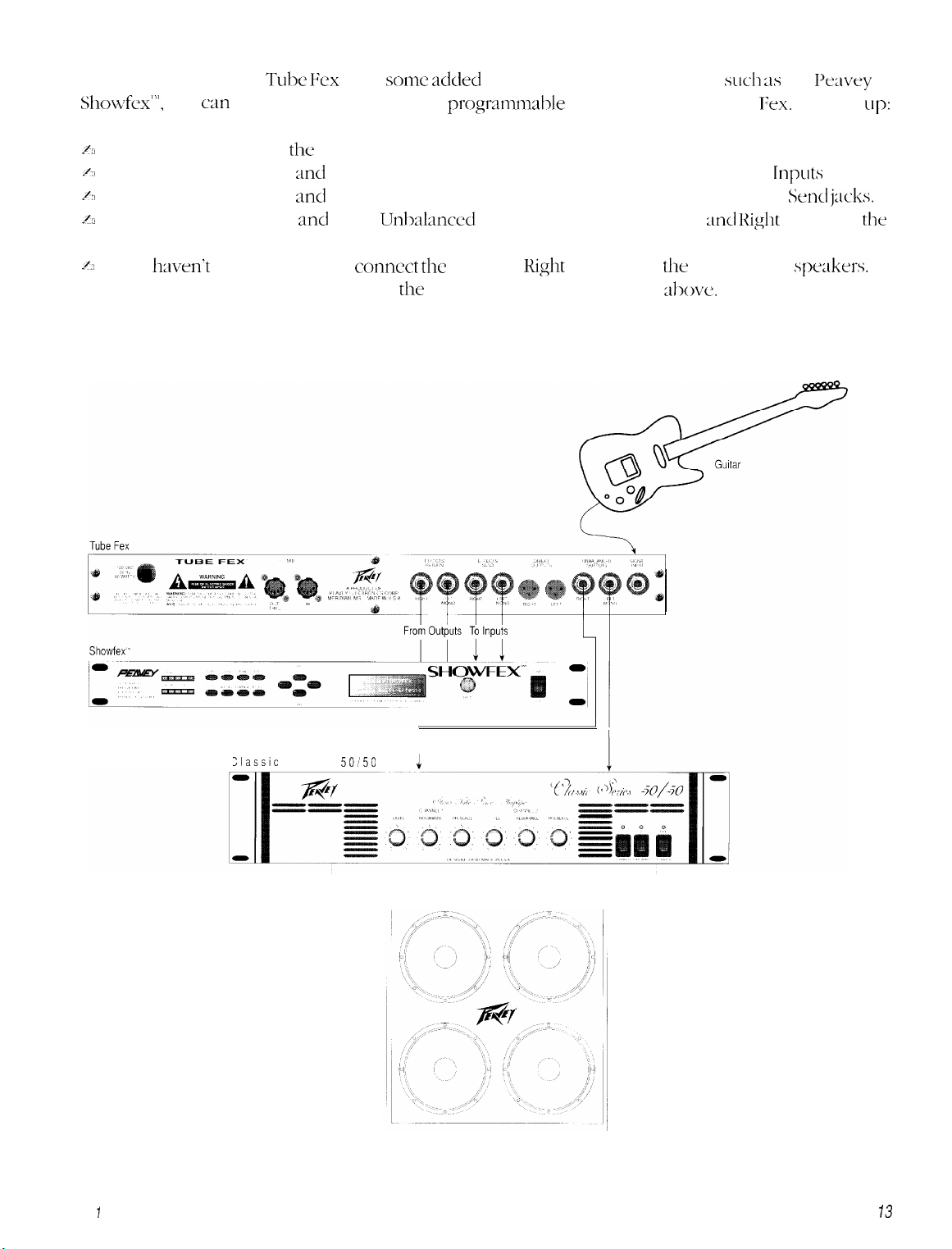
3. Using a separate preamp, distortion box, or effects processor in the Tube Fex effects loop.
If you wish to use the Tube Fex with
Showfex”‘,
/J
Connect your guitar to
~(3
Connect the Left/Mono
A
Connect the Left/Mono
~3
Connect the Left/Mono
you
can
put that processor into the
the
Signal Input jack on the Tube Fex.
and
Right Effects Send jacks to the external device’s Effects
and
Right Effects Return jacks to the external device’s Effects Smd
and
Right Urhalanced Outputs (stereo) to the Left
some added
pr”gr;ltl~m;ll,le
outboard effects processing,
effects loop of the Tube
and Right
such as
Fex.
the I+avey
To hook
Inputs
jacks.
j:lcks.
Inputs of
up:
the
amplifier, respectively.
2~
If you
Note: For mono operation use only
hven’t
already done so, connect
the
the
Left and
Right
Outputs of
the
amplifier to
Left/Mono jacks in the steps shove.
spakers.
Chapter
Iasslc
Series
Setup
1
50150
4
Classic 41 OE
73
Page 13
4. Using the Tube Fex in the effects loop of a separate preamp.
In this case, the Tube Fex is used as an outboard effects processor of your preamplifier. To hook up:
$50
Connect your guitar to your preamp’s input.
b
Connect the preamp’s Effects Loop send to the Signal Input jack on the Tube Fex.
b
Connect the Left/Mono and Right Unbalanced Outputs to the Left and Right Loop Return of your
preamp, respectively.
h
Connect the Left and Right Outputs of your preamp to your amplifier’s audio inputs
fi
If you haven’t already done so, connect the Left and Right Outputs of the amplifier to speakers.
Note: For mono operation use only the Left/Mono jacks in the steps above.
To Signal Input of preamp
Tube Fex
Classice
Series 50150
To Loop Return
1
.
From Loop Send
From Audio Output
74
Classic’ 410E
Chapter
7
Setup
Page 14
5.
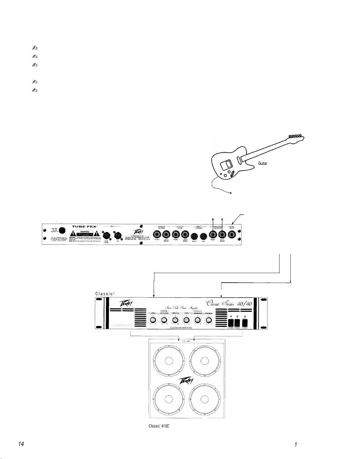
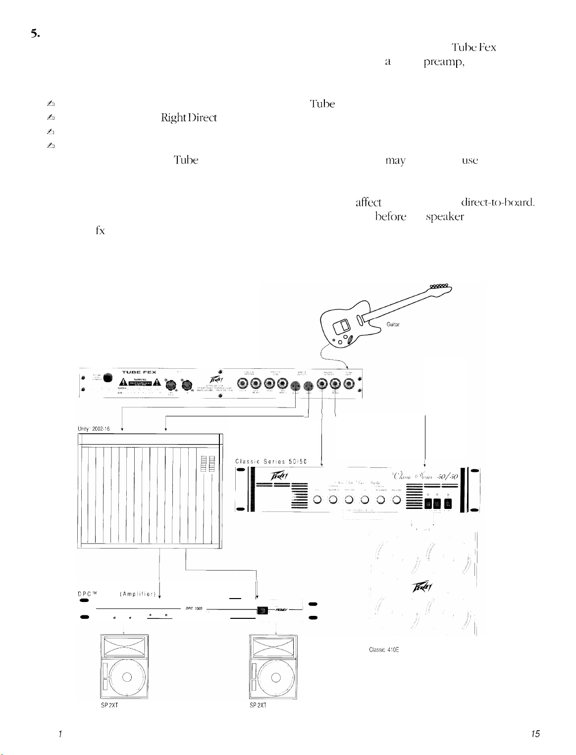
Direct connection to a mixing console.
When recording direct, or in some live situations, connect the Direct Outputs of the Tube &x directly
into two channels of a mixing console. If you are using the Tube Fex as a guitar
pre;~mp,
you may want
to experiment with building sounds using the Speaker Simulator effect. To hook up:
h
Connect your guitar to the Signal Input jack on the Tube Fex.
A
Connect the Left and
h
Connect the Left and Right Outputs of your mixer to your amplifier’s audio inputs
A
If you haven’t already done so, connect the Left and Right Outputs of the amplifier to speakers.
Note:
We’ve found the
Right Direct
Tulx
Fex to be so recording friendly that you
Outputs to the Left and Right mixer inputs, respectively.
may
not need to
use
the Speaker
Simulator. Experiment and see.
Also, if you use the speaker simulator, you may want it to only affect the sound going
direct-to-~->oard.
To get signal to your monitor amplifier insert the fx loop directly before the speaker simulator and
use the fx loop sends to carry signal to your monitor amplifier.
Tube Fex
1
Classic Series 50850
DPCTM
0
0
Chapter ISetup
1000
SPZXT
(Ampllfler)
"
0
----
----
c
0
----
DPC iooo
~
I
Classic 410E
SP2XT
15
Page 15

THE
FIRST
This procedure is recommended the first time your Tube Fex is turned on after purchase from your Peavey
dealer. This ensures that the memory is initialized and that the battery is fully charged.
Z3efollowingp~ocedu~e will overwrite all changes made to
facto y settings. Only
1.
While holding both the v (down
the unit by hirning on the power switch.
The unit has now been initialized to factory settings. It is recommended that you leave the unit turned on
for at least three hours at this time to ensure the battery has a full charge. The unit’s battery should then last
several years before replacement is required. The unit will warn you when the battery is getting low.
Battery replacement must be performed at an authorized Peavey Service Center.
T/ME YOU TURN IT ON (RE/NlTlAL/ZATION)
WARNING!
the
unit’s memo y
peeom
-
the following if you desire to re-initialize the unit.
/dec
_
arrow) and
rig&
arrow buttons on the front panel, power up
storuge, yeplacing
them with
Adjusting
(Very
Once the connections are all made, set up the input and output levels of the Tube Fex as follows:
Turn on the Tube Fex and press the Global button until you get to the
to 0: input level knob on the front of the Tube Fex, output level knob on the front of the Tube Fex, and the
input level control on your power amp (if it has one).
Adjust the input level control on the front of the Tube Fex while playing your instrument. The level should
be set so that the
Then turn on your power amp. Set the input level control on the amplifier to your normal playing level. No
sound will be heard from it yet.
Finally, slowly adjust the output level control on the front of the Tube Fex while playing until a suitable
playing level is reached.
Set the Bass, Mid and Treble levels to taste. These settings are global. This is a very handy feature. For
example: If you develop your effects at home and then go to a live stage and notice that there is not
enough high end in that particular room/stage, all you must do is go to the
the Treble (to taste). This will affect all of your patches.
The
Global Input And Output
Important)
Active/Clip
Levels,
LED just begins to turn red on your absolute loudest playing level.
and
Global EQ
[GLOBI
display; set all level controls
[GLOBI
display and adjust
16
Chapter
7
Setup
Page 16
Chapter 2 Overview
GETTING STARTED
After connecting and
continuing on. This short section describes how you
description of some of the functions of the optional MIDI Foot Controller.
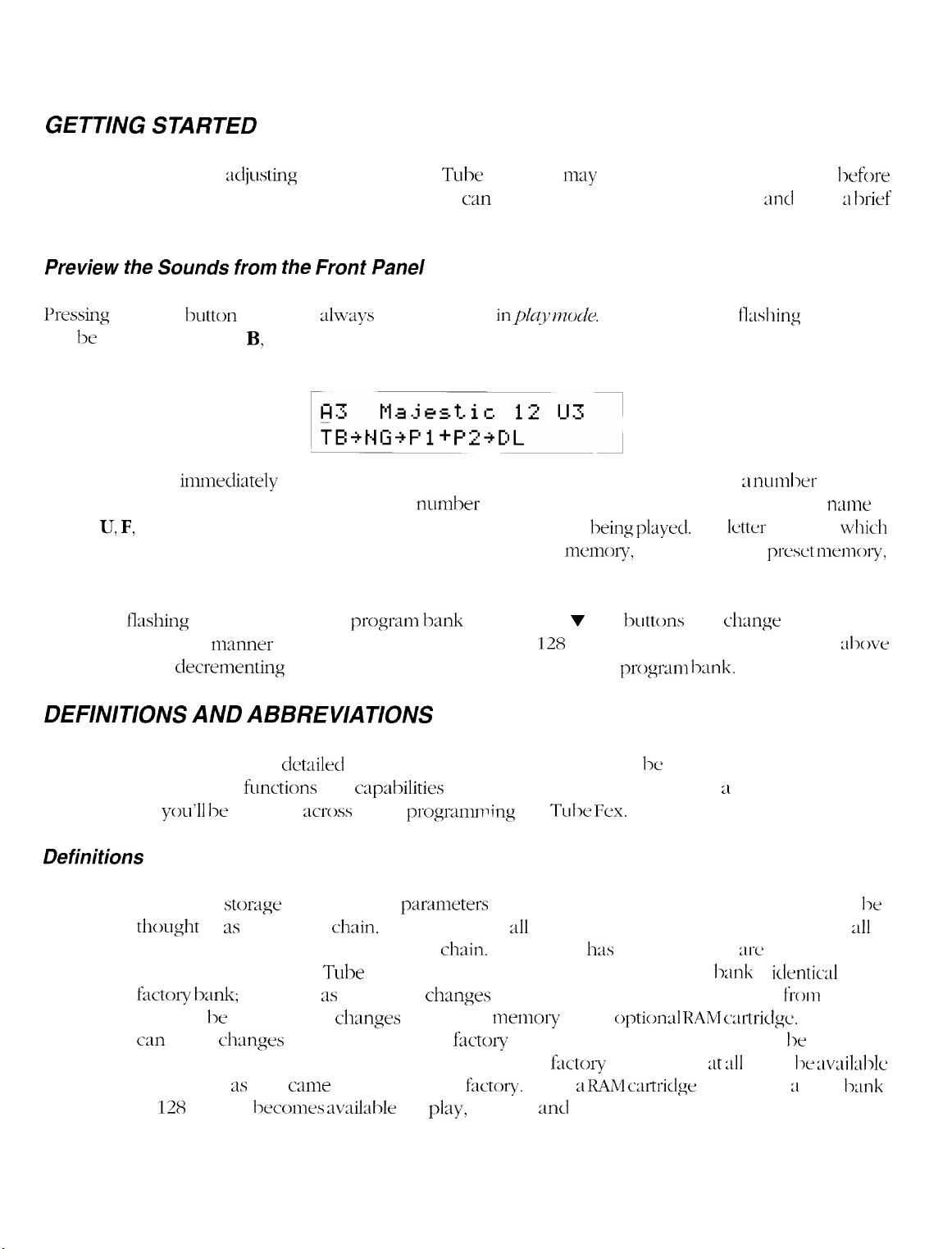
Preview
I+essing the
will be under the letter
that is currently selected. (See the section titled, Setting Up Your Programs.)
The number that
0 and 127. The name that follows the program number is the preset name. Following the preset
a letter U, F, or C and the
preset memory bank
and C is for
While the
being played. In this
program 127 or
the Sounds from the
Play
cartridge
I-lashing
decrementing
:idjusting
the levels on the Tube Fex, you
c;in
quickly access each of the sounds
n~ay
wish to preview the sounds hefore
Front Panel
button twice will
A, B, or C in the top left corner of the display. This letter indicates the
immedizttely
preset number.
this preset is stored in: U is for
preset memory.
cursor is under the
nunner
:llways
follows the program bank, is the program number. It is ;I number between
you can listen to each one of the
below program 0 will switch to the next progr~n
ensure you are
This is the
program
bank pressing the v or A
in$q 73~)&.
preset
user
The cursor (short fl;lshing underline)
currently being
preset memory,
128
presets in the bank. Incrementing
plztyed.
F
is for
buttons
will
The
letter
factory
chqge
bank.
:lnd
gives ;I
program bank
indicates which
preset n~emory,
the program
llrief
n:lme
al~)ve
is
DEFINITIONS AND ABBREVIATIONS
Before continuing on into the
terms used in describing
abbreviations
you’ll
be running
Definitions
Preset:
This is the
thought
continuous controllers for that effects
memory banks
klctory bank;
you will 1~ saving these
can make changes to the presets in the
locations in the user memory or the cartridge. The
unchanged,
of
128
storqe
of 3s the effects
21s
presets
cle~~iled
functions
location of all
in the Tube Fex:
however, 3s you make
they came from the Peavey
l->ecomes availat->le
operations of the Tube Fex, it would 1~ helpful to understand some
and
cap:lbilities
gross
while
chain,
ch:~nges
programn+ng
parameters
the settings for
factory
in the user
for
of the unit. Also presented here is ;l reference list of the
chain.
and
ch:mges
f;lctov
fr1ctot-y.
play,
editing,
the Tube
pertaining to the sound itself. The preset can
311
effects in the chain, and the settings of
Each preset
user.
to the presets or create new presets
memory
memory, those changes can only 1~ saved to
When ;i
:md
Fex.
h:ls
a name. There
When new, the user
or the
f;sctoly
option4 RAM c;trtridge.
presets will
IIAM urtridge
storage.
is installed, ;I third bank
:11-e
l->:lnk
:lt 2~11
times 1~
two preset
is
identiul
from
scratch,
While you
:lvailable
to the
l->e
311
Chapter 2 Overview
17
Page 17
Program:
A program is what changes when the Tube Fex responds to a MIDI program change command
(such as those sent to the unit from an optional foot controller). Programs are merely pointers
to presets. This really comes in handy when setting up your performance. You can arrange your
presets into sets and banks so that they can easily be recalled in playing order from the front panel,
from an optional foot controller, or via MIDI. The Tube Fex has two banks of programs inside
it: Bank A and Bank B. Each has 128 programs in it, and each of these can be set to recall presets
from either user preset memory, factory preset memory, or from the cartridge. The cartridge also
provides a third program bank (bank
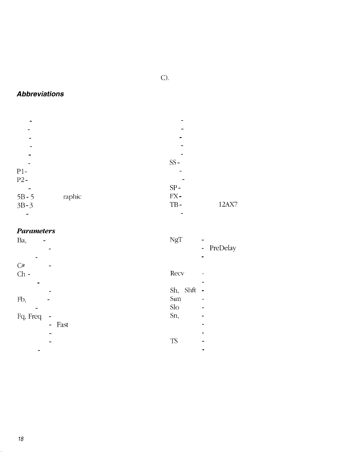
Abbreviations
Effect Types
CM - Compressor
DS - Distortion
OD - Overdrive
CH - chorus
DL - Delay
HF - Hum Filter
Pl -
Pitch Shift 1
~2 -
Pitch Shift 2
RV - Reverb
raphic
5B
-
5
Band G
3B - 3 Band Sweep Mid Equalizer
4B - 4 Band Parametric Equalizer
Equalizer
C).
CQ - ‘Classic’ Equalizer
PN - (Auto) Pan
EF - Envelope Filter
CT - Coil Tap
EX - Exciter
SS -
Speaker Simulator
ST - Stereo Simulator
NG - Noise Gate
SP -
Splitter
F!X -
Effects Loop
TB - Tube (two 12Ax7 tubes)
TR - Tremolo
Parameters
Ba,
Bal - Balance
BP
-
Band Pass
BW - Bandwidth
C#
Ch -
Channel
Control number
-
Env - Envelope
-
EXEC
Fb,
Fdbk - Feedback
Execute
Flt - Filter
-
Fq,
Fst
L
LP
Freq
Frequency
- Fast
-
Left
-
Low Pass
Lvl - Level
NgT
PD, Pdly
Pram
R
Recv
Re, Reson
Sh, Shft Slm
Slo
Sn,
Sens
Spkr
Thr
TS
Xmit
Noise Gate Threshold
PreDelay
-
Parameter
-
Right
Receive
-
Resonance
-
Shift
Simulator
-
Slow
-
Sensitivity
-
Speaker
-
Threshold
-
Tape Simulator
-
Transmit
-
78
Chapter 2
Overview
Page 18
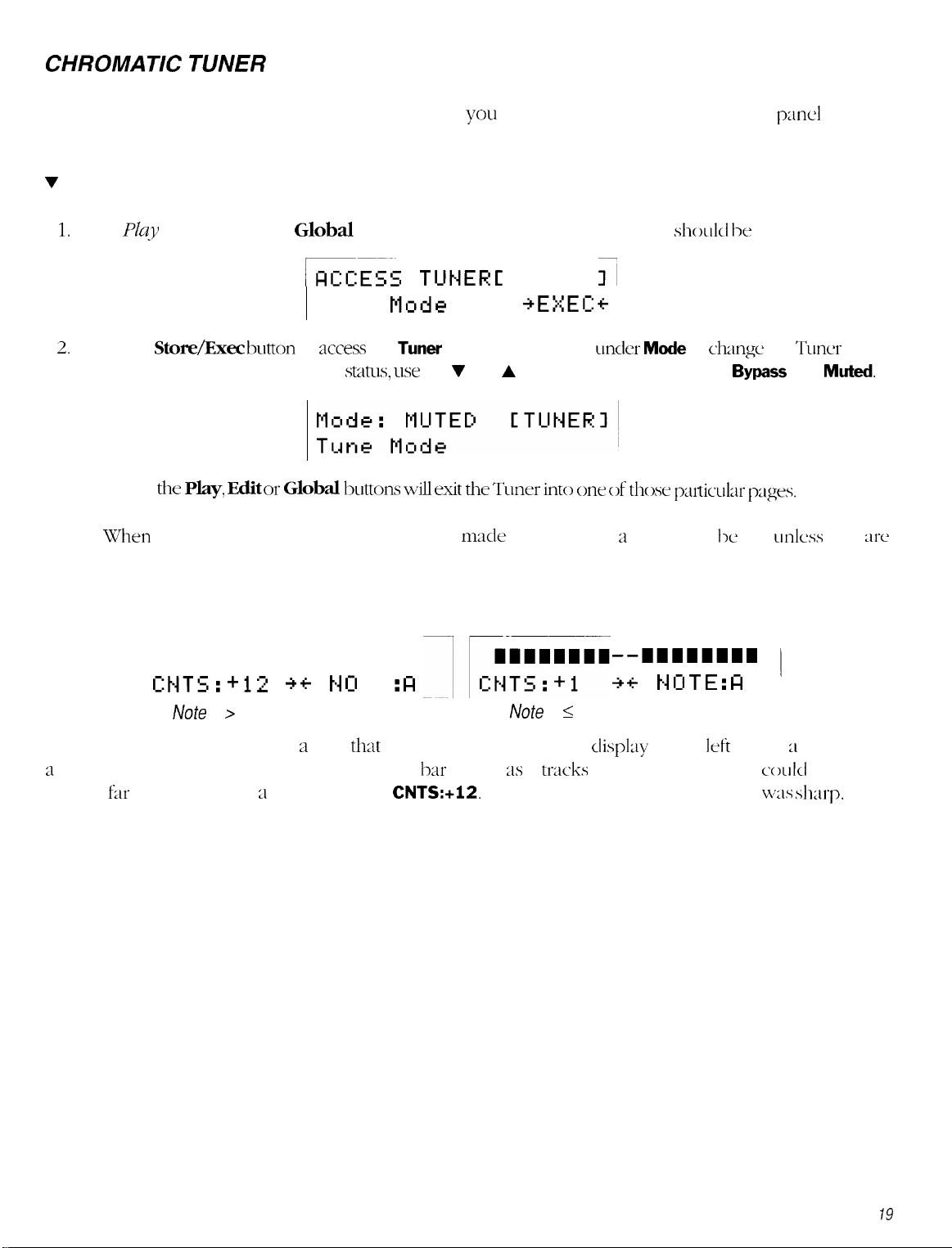
CHROMATIC TUNER
The Tube Fex comes with a chromatic tuner to allow
To access the tuner:
V
Chromatic Tuner
1.
From
2.
3.
Note:
JYq
mode, press the
Global
GEzz
Tune
Press the
status. To change the Tuner mute
Pressing
\Vhen
first stored.
St~re/Exec button
the Play,
entering the Tuner mode, any changes
Edit or
to
access
status, use
Global httom will exit the TLlner do
button one time. The following screen
TUNER C
Mode
the
Tuner
or move the cursor
the V and A buttons to change between
you
to tune your guitar using the front
sl~o~~l~l lx
TUNER
I’
+EXEC:+
u-&r Mode
one of
mzade
while editing ;I preset will lx lost
those phhr
to change the Tuner mute
p;uxl
displayed:
Bypass
pges.
and
udess
display.
Muted.
they
xe
4. When the Tuner is accessed, you should see a display similar to one of the following:
----------I I------
C:tjTS:+l2
Note
is > 2 cents of being in tune.
The display on the right shows a note
a
little sharp and should be adjusted. Since the
the bar
far
to the left with ;I cents value of, CNTS:+l2. This would indicate that the note
+ +t4 0
T E :
that
is, essentially, tuned. The
FI
bar
moves
Note
is 5 2 cents of being in tune.
21s
it
tracks
--11111111
t-1 15 T E :
+
+
display
the note, this display
on the
n
Ieft
shows ;I note that is
codd
also show
was shad-p.
Chapter 2 Overview
19
Page 19
Chapter 3 Editing Programs
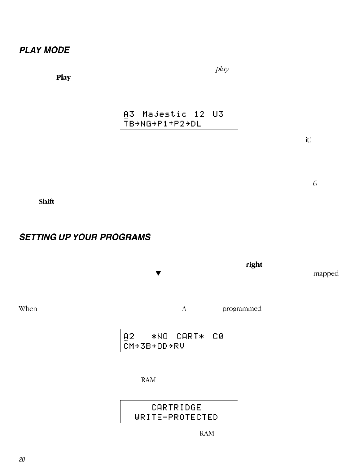
PLAY
Most of the time during performance, the Tube Fex will be in the
pressing the
change command (such as those sent by an optional foot controller). A typical display for play mode is shown
below:
MODE
Play
play
mode. The play mode is accessed by
button. The Tube Fex also switches to play mode each time it responds to a MIDI program
173 Majestic
12
U3
TB+twPl+P2+DL
As described in the quick start section, the first letter A in the display (with the flashing cursor under
that the program being played is in program bank A. The number following it is the program number. The
name is the name of the preset which that program points to. The U indicates that this preset is stored in user
preset memory, and the number is the number of the preset.
On the bottom line of the display are the first five effects in the effect chain. (If the chain is longer than 6 effects,
the others will not be shown. In this case, the chain is: Tube preamp is series with Noise Gate in series with
Pitch
Note: Lower case letters indicate that the effect has been bypassed.
Shift
1
in parallel with
Pitch
Shift 2 in series with Delay.
it)
indicates
SETTING UP YOUR PROGRAMS
Any program from any bank can call up any preset. In performance this is an extremely handy feature. To
change which preset is called by the program currently selected, press the
cursor is flashing under the preset name. Use v or A buttons to select the preset you desire to have
to this program. Changes are automatically stored, so this is all you have to do. Press the left arrow button
to select the program, switch to the next program, and set it up by repeating the above steps.
When a RAM cartridge is installed, programs in bank 11 or B can be
on the cartridge. If at a later time the cartridge is removed and this program is selected, the display will show:
FE
*tW
GIRT*
programmed
C0
?M+3B+OD+R’v’
The sound being played will not change. You should replace the cartridge, or select a new preset for this program.
A third program bank is available on the
that the cartridge write protect is disabled; otherwise you will get the following message:
RAM
cartridge. ‘When reprogramming this bank, you must ensure
CFIRTRIDGE
WRITE-PROTECTED
right
arrow button so that the
to point to presets stored
mdpped
The program will not change. For more information on the
20 Chapter 3 Editing Programs
RAM
cartridge see chapter 5.
Page 20

PERFORMANCE PARAMETER CONTROL
Most effects’ parameters can be varied during performance via MIDI control change
available from the optional foot controller. Each preset can have up to eight parameters that respond to these
changes. Most of the factor); presets are set up with controllers assigned to them
mode of the foot controller to control change. Select an active controller by pressing the necessary buttons
on the foot controller corresponding to the effect to be controlled. Now using the v or A buttons, you can
change the value of that parameter during performance.
conmands.
(SW the playlist).
These are
Set the
VOLUME CONTROL DURING PERFORMANCE
The Tube Fex will respond to MIDI volume change messages (controller #7 >. These changes are global. That
is, they affect the unit even after the program is changed. A CV pedal assigned to controller #7 will act as a
MIDI volume pedal. You can reassign the volume to a different control
be controlled from the front panel, but this is not usually done during performance. See chapter 4.
nun~ber
if you wish. Volume can also
Chapter 3
Editing Programs
27
Page 21

Chapter 4
There are four major functions that can be performed via MIDI on the Tube Fex: change Programs/Banks;
change effect parameters during performance via Continuous Controller messages; store presets on remote
storage devices via MIDI system exclusive messages; and remotely edit and store any user accessible
parameter using special Remote Editing
program change messages when a new program is selected from either the front panel or via MIDI.
Using MIDI
SysEx
messages. The Tube Fex can also be setup to transmit MIDI
TRANSMITAND
MIDI messages are transmitted and received on one of sixteen different MIDI channels. The unit can be set
to transmit messages on any of these channels, and to respond to valid incoming messages on any one or
all sixteen channels. To change the channel the unit receives on, press the
appears as below:
The cursor is flashing under RC (Receive Channel). Use the V or A buttons to select MIDI channel l-16 or
OMNI. OMNI
To change the MIDI channel the unit transmits on, press the
TC
(Transmit Channel). Use the V or A buttons to select the desired MIDI transmit channel (one through sixteen).
To turn the transmit program change feature on or off, use the
flashing cursor under
When
each time the program is changed either from the front panel or via MIDI (including changes sent from an
optional MIDI foot controller).
ON,
will allow your unit to respond to valid MIDI commands received on any channel.
Transmit Program change will send a MIDI Program Change message out on the transmit channel
RECEIVE CHANNELS
Global
Recu
RC TC TP DP LP DS
TP
(Transmit Program Change). Use the v or A buttons to turn this feature
Ch=l
right
CMIDI 1
LS
arrow
button. The cursor is now
right
or left arrow buttons to position the
button until the MIDI menu
fl&ing
ON
under
or
OFF.
The other functions on the MIDI menu are system exclusive functions and are described in the section titled
System Exclusive Remote Storage.
MIDI PROGRAM
The Tube Fex will respond to valid
receive channel. Program changes will cause the unit to recall a program within the program bank currently
selected. There are two banks of 128 programs in the unit’s memory, bank A and bank B. A third bank,
becomes available when the optional RAM cartridge is installed. Program banks can be changed on the front
panel by incrementing the program above 127 or below 0 while in play mode, or by sending a MIDI bank
select message to the unit.
22 Chapter 4
CHANGEAND BANK
MZXP~oqam
SWITCHING
Change and Bank
5’eZectmessages
received on the unit’s
C,
Using MIDI
Page 22

The
format
of the
IMIDI
lxmk select message is:
(all
nunbers
HO 00 00 20
in
1iex;idecimal)
00/01/02
where:
130
00
00
20
00/01/02
A MIDI bank select
program is changed either via MIDI program change or
To set up the preset-to-progmn
=
MIDI continuous controller 0 (bank select)
=
bank high byte (always
=
MIDI 2 byte data indicator
:
00 selects bank A, 01 selects bank B, 02 selects
comnmd
will tell the unit to switch to a
0)
from
map,
see chapter 2.
the front
M/D/ CONTINUOUS CONTROLLERS
Many of the
assignments are set up to take advantage of the
optional MIDI foot controllers. Continuous controllers
depending upon the
not in Preset nieniory or the edit buffer. Continuous controllers
for variation during performance. For a description of how to
chapter 3. For ;I list of controller assignments of the
factory
presets in the Tube
vdue
of the controller message received. These
Fex llave MIDI
continuous controllers assigned to
GmeraZ Pzqbc~.s~ Cmtmllw
make tempor:lq chtmgus
fxtory
presets. see the
lxmk
C
program
in the new
panel.
chmges
x-e
not intended for s(
Lssign
controllers to
bank the
next time the
them. ‘1’1~ c.ontroller
messagt~ transmittccl by an
to
dect pat‘anlctms
are
only
made in the 1
xmcl
editing,
lmt
c+ExYt p:~i*;tinetei-s,
pklylist.
>SP md
only
see
MID/ VOLUME CONTROL
The
Tube Fex
on or off, climge the controller
volume
Press the Global
With the cursor
level
3ffects all
n-e refer to it 3s the
To turn the
the bottom line of the
To
change
bottom
responds to
,\,!I111 1 ‘o/?l/lzc~(~ontr~)~~l-7)
tlxlt volunic’ rqxml.5
level. These functions are
lmtton se\7eral times
flmhing
presets md
under the
renxiins
~k,ha/~.olume.
MIDI ~olurne feature
displq. USV
the controller
line, and
use
nundxr
the V or A
pt’rfbnned
the
ON, press the
on the
until
volunie
the volume menu app~rs ;IS Ixlc w:
le\d,
smie e\.en \z.liile
the V or A
to
\xhich
the
Imttons
to select ;i new
conmxmd~
to, change the
Volume
use the
right
buttons
~~)lutne
menu
V of A
arrow
to turn
responds,
on its
recei\,e
rqx mse sde, (x inaniially
undc~ the
l~uttons
climging
lmtton
MI111 W~U~W
controller
chmnel.
Global
to
adjust thv vc~lcrinv. This
from ant’ lxesct
to
~ncn.e
the cursor mclcr
ON or OFF.
pl:tcc
the
C’II~SO~ unclcr tile # sign
nunibm
You
hrttc
may
turn
this
dxmgc the
m.
to
3tiotl1cr. ‘l’li3t’s b;l>p
midi:OFF
function
gI( )l,al
voluint
on
on
the
Chapter 4
Using
MIDI
23
Page 23

The MIDI Scale can change the range of volume affected by the controller. A Scale of
range control. To vary this, place the cursor under SC for scale and use the v or A buttons.
+50
will give you full
MIDI SYSTEM EXCLUSIVE REMOTE STORAGE
The Tube Fex can utilize MIDI System Exclusive (SysEx) to store and reload presets on a remote MIDI
storage device such as a Peavey MIDI Librarian’“, MIDI Streamer’“‘,
computer equipped with MIDI and the appropriate software. The Tube Fex can dump
presets, sets of ten presets, or individual presets. When reloading sets or individual presets, they can
be loaded back to where they originated or into any other set or preset location. Presets can even be
reloaded directly into the edit buffer.
DPM@ 3,
or other sequencer or
all
the user
MIDI SysEx functions are in the MIDI menu under the
until the MIDI menu appears.
Recu
RC TC
To dump a single preset to an external storage device (or another Tube Fex): In the MIDI menu display press
the
right
or left arrow button until the cursor is under DP (Dump Preset).
Ch=l
TP DP LP DS LS
Durw Prst. Ul
RC TC
Use the v or A buttons to select the preset(s)
Exec button to execute the dump. The display will briefly show:
Note:
The MIDI transmit channel of the Tube Fex must be set the same as the MIDI receive channel on the
external device unless the external device is set to OMNI.
TP De LP DS LS
(l-128,
Global
Prst All,
button. Press the
[MIDI1
+EXEC+
or
Edit Buf)
to be dumped. Press the
Global
button several times
Store/
24
The Tube Fex can also dump sets of presets. The sets are arranged as follows:
Set 0
Set
1
Set
2
Set
3
Set
4
Set
5
Set
6
Set
7
Set 8
Set
9
Set
10
Set11
Set12 120-127
O-9
10-19
20-29
30-39
40-49
50-59
GO-69
70-79
SO-89
90-99
100-109
110-119
Chapter4
Using MIDI
Page 24

To dump a set of presets to an external device (or another Tube Fex): In the MIDI menu display press the
right
or
left
arrow button until the cursor is under DS (Dump Set).
11Jse
the 7 or A buttons to select the set (O-12) to be dumped. Press the
dump. The display will briefly show:
Store/Exec
button to execute the
Note:
The
MIDI
transmit channel of the Tube Fex must be set the same as the
external device unless the external device is set to OMNT.
MID1
receive channel on the
LOADING SETS OR PRESETS TO THEIR ORIGINAL LOCATIONS
To load sets or presets to their original locations from an external storage device or another Tube Fex,
set the
Tube Fex). Then send the set or presets to the Tube Fex. That’s all there is to it!
Note: See the owners manual of the storage device for instructions on sending
LOADING SETS OR PRESETS TO
To load sets or presets to a new location. Set the MIDI receive channel to match the
the external storage device or Tube Fex. Then select LP (Load Preset) if loading a preset to a new location
or LS
the Tube Fex.
Note:
MTDT
receive channel to match the MIDI send channel on the external storage device (or other
MIDI
dumps.
NEW
(Load
Set) if loading a set to a new location. Select the new location. Then send the
The
MIDI
receive channel of the Tube Fex must be the same as the channel the data was
transmitted on. An error message will appear if they are not the same. If this occurs, set the receive
channel to the channel shown in the message :: ~1 transmit again.
LOCATIONS
MI111
send channel on
preset
or set to
omj+d~y
REMOTE EDITING USING MIDI SYSTEM EXCLUSIVE
A set of special system exclusive editing commands is available on the Tube
programming of all effect parameters, effect levels, the effect chain, and
The edit buffer can also be stored in any user preset location remotely. These changes
immediately, but will not appear on the screen unless the
Appendix B
or
s0ft3m1-e.
Chapter 4
for complete remote editing command information for programmers of
Using MIDI
parameter
continuous
being edited is currently selected.
Fjex.
This will allow remote
controller assignments.
rem( w ect iting
can t>c
devices
heard
SW
25
Page 25

HOW TO SETUPA
CONTIAIUOUS
CONTROLLER
For this example let’s walk through the steps required to create a
controller pedal. Assuming you have a continuous pedal hooked up to the Tube Fex via a MIDI foot controller,
first select or write a patch that has the envelope filter (EF) effect and store it. Then push the Edit button,
select
EF
and push the
Move the cursor under
your foot controller has channel 7 as a continuous channel send. Next push the Global button until the
following screen is displayed:
Move the cursor under Pram and use the 7 and A buttons to select Freq. Next move the cursor under
and select
select
effects. You can set the scale anywhere in between to adjust the effect to your tastes. Next press the
and move the cursor under
and select a frequency, try
cursor under
work the continuous controller pedal to try the effect. Adjust the envelope filter parameters and the scale to
suit your taste. Press the Store button to save the settings and continuous controller to your preset.
Cntrl#=7.
+lOO.
It is
Ty
Edit
button again. Next, push the
REIGV
RC TC TP DP LP DS
“^
RC
and use the V and A buttons to select channel
Et#.JFLT
#I
Pram C# Ch
-
Next move the cursor under Ch and select RCV. Next move the cursor under SC and
impor&nt
to select a filter, try
to note that the scale can be set from HO0 allowing normal or reverse wah
Sn
and select a sensitivity level. Try
50.
Next move the cursor under Rs and set the resonance, try 52. Next move the
LP-Slo.
Ch=l
Frvi
Next move the cursor under
Global
CMIDII
CCHTRLI
SC
“wah
wah” effect using a continuous
button until the following screen is displayed:
LS
1.
For this example we will assume
C#
wall
Edit
button
+48
to start. Next move the cursor under
Mx
and try a mix level of 50%. Now
Fq
Note:
Move the cursor under
parametric EQ to create this effect.
If you get volume control instead of wah wah, push the Global button until the following screen is
displayed:
midi
and change the setting to
VOLUME=100 CVULI
#7
rni-di:Ot4
OFF.
SC=+54
Now try your effect.
You
can also use the
4-band
26
Chapter 4
Using MIDI
Page 26

Chapter 5 RAM Cartridge
The optional
be accessed
internal user
to any preset in cartridge, user, or
Note: The RAM cartridge menus are accessed through the Global button.
/NIT/A
RAM Cartridges are sold separately by your Peavey Dealer. Ask for the
new, cartridges must be initialized for use with the Tube Fex. To do this, press the Global
get to the CART menu. Place the cursor under In (Initialize), and press the
RAM
individually,
memory.
L/ZING
Cartridge acts as a memory extension for the storage of
and played directly off the
The 128 additional programs appear as program bank C and can be set up to point
NEW
factory
CARTRIDGES
preset
RAM
memory.
cartridge without the need to move
128
additional presets. Presets can
C’U?W Ctird 32
Store/Exec
part
#7/02.3.
button
button.
them
into
When
until you
SAVING PRESETS ON THE CARTRIDGE
Presets may be stored individually to the cartridge by using the normal store procedure, or all
may be saved on the cartridge by using the
writes program bank A into the program bank C, converting all pointers to user presets into pointers to
cartridge presets in the process.
Save User -> Cart
fLlnction
on the CART menu. This function also
user
presets
LOADING PRESETS FROM THE CARTRIDGE
Cartridge presets may be recalled individually from the cartridge to the edit buffer, or all presets may be loaded
to user preset memory by using the
program bank C into program bank A, converting all pointers to cartridge presets into pointers to user presets
in the process.
Load Cart -> User
function on the CART menu. This function also writes
CARTRIDGE BATTERY
Most cartridges have a replaceable backup battery which maintains memory storage while the cartridge is
removed from the unit or the unit is turned off. The battery will last from two to five years depending on the
model. If the battery becomes low, the unit will warn you by periodically displaying the following screen:
Note: If this message is displayed you should back up your cartridge data immediately, then replace the
battery and restore the backed up data to the cartridge.
Chapter 5 RAM Cartridge
27
Page 27

Tutorials
Here are several of the most common functions performed with the Tube Fex in tutorial form.
Editing
Why edit a preset?
to adjust parameter settings to achieve the sound you are looking for. The easiest way to do that is to edit
an existing preset and store it to a user location (since the factory presets are “read-only”). Initially you may
notice that the factory presets and the user presets look identical-they are. They are also identical whenever
the Tube Fex is initialized. This is because the Tube Fex copies all the factory presets to the user preset
locations when initialized. So if you don’t want to lose your presets, we suggest you save them via MIDI. The
MIDI Streamer’“, a MIDI Data Storage Processor, from Peavey is an excellent choice for doing this.
1.
2.
and
Storing a
While
Press the
name/number in this example is
Press the
Play
Edit
Preset
we try to provide presets that kick a. .
button and use the v and A buttons to select the preset you want to edit. The preset
Abduction U4.
button one time.
. uh, that is, are useful, sometimes it is necessary
Position the cursor under the effect you want to edit. Use the
3.
Press the
4.
Position the cursor under the parameter you wantI( ) change.
5.
move the cursor.
6.
Change the value using the v and A buttons. (Go ahead, experiment!)
Repeat steps 3 through 6 until all changes are made.
7.
8.
Now its time to store the changes you made (you don’t want lose your changes, do you?).
Press the
9.
Edit
button again.
Store
m
button.
?TORE C~bductim
;OUIRbductionm
From this display it is possible to change the name of the preset and set the storage location.
10.
To change the name: Press the
11.
then use the V and A buttons to change the character.
12.
To change the storage location: Press the
then use the v and A buttons to select the new user storage location.
That’s it! You have just successfully edited and stored a preset. Congratulations!
13.
left
arrow
left arrow
button until the cursor is under the first character of the name,
left
and
right arrow
$zEq
Use
the
1
button until the cursor is under the storage location,
left
buttons to move the cursor.
and
right
arrow buttons to
28
Tutorials
Page 28

Program Mapping
‘TWX
the night before Christmas and all
1nouse.
. . whoops, wrong
stoly.
through
the house not 3 creature was stirring, not even
a
Once upon a time there lived a musician who
to
chqqe
at a time. .
from one preset to the next (he had only one button to use,
.gasp!‘).
He wished that it was possible to take his favorite and most useful presets
in such a way that he could move from one to the next with ease,
that would be too cumbersome. It
program mapping. This magical thing
presets in whatever order he chose-it
Okay,
to the next when
maybe
a Program Map isn’t
you
are using the front panel, or 21 foot controller with an increment and
A Program Map is simply ;I diagram
DualGuitar
When
nelv,
U
1).
or
reinitialized,
the Tube Fex restores the Program Map to the factory
was
then that this young
called a Program
was
‘~wondro~is”
that
was very
discouraged with the
musician
Map allowed the musician to place
a dream come true,
or even
points
“magic:il” but
fi-on1
a program
but
discovered a wondrous
and
he
it is a useful
hay,
program number corresponds one-to-one with the preset number (e.g.,
The following tutorial should help to illustrate the usefulness of the
Suppcxx
to them from
you ha\le
the
the following presets that
you
front panel of the Tube Fex:
use
all
the time
and
Pr~gr;im
you want to 1~
trdde
and
all it did was go up one preset
he didn’t want to
he had to go through
and
place them
reprogram
invention-
;tII
his favorite
progranin~ed lqpily
way
to move
fi-c
ever
~11
(
declwment 13utton.
Al > to ;I preset (for instance,
AO=I
defdt
JO. .
settings, where the
.ASO=l JSO,
etc.
>
Map.
al~le
to have
cl~lick
)ne
them,
after.
preset
;~ccess
Preset
#
IJllO
Fl12
u12
F64
Going from one preset to the next without mapping them would
had to put up with.
Luckily,
ure are
going to show
Preset Name Current Program Map #
Thr-uO
OLltOfPllase
SwarmKorus
FOLLOW
(Just
think
Dirt
WAH
about
you an asier
changing from
All0
I3112
A12
B64
ThruODirl
way using the
be nearly as Id 3s what oiir young musician
t
to
Program 11x1~. Pay
to do this once.
1.
Press the Play button. This places
number
and
the preset
rume/numher
Cursor under Program Number
2. Press the right arrow
program number AO,
button
but
allows you to change the preset
you
in the
play
mode. In this mode you can view
on one screen. For instance:
1
Cursor under Preset Name &Number
one time to place the cursor under the preset name. This
name/numl->er
Target Program Map
A0
Al
A2
ArS
OutOfPhase
using the V
attention, we’re only going
-
assigned to AO.
#
and A
Id1 the
I
leaves
buttons!)
program
you in
Tutorials
29
Page 29

3. Use the V and A buttons to change
the Tube Fex-“I want to stay in program number AO, but I want to change the preset that program
number A0 calls up from
4.
Press the
the cursor is under the program number, both the program number and the preset name/number change
when either the v and A button is pressed.)
5.
Press the A button one time to move to program number Al. This is like saying -“Okay, I’m through
with program number AO, now I want to go to program number Al and assign a preset to it.”
lefi
arrow button one time to place the cursor under the program number. (Notice that when
Pouiindcake UO
Poundcake UO
to
ThruO
to
ThruO
Dirt U
Dirt U
110:
110.
At this point you are telling
RI
DualGuit.ar
Ul
;P~TE~~~~DL~CM~~~~~H~
6. Press the right arrow button one time to place the cursor under the preset name.
7. Use the V and A buttons to change
8. Press the
9.
Press the A button one time to move to program number
lefi
arrow button one time to place the cursor under the program number.
DualGuitar
~ ;;jcT:;;t;;h-r
Fl12-1
U
1
to
OutOfPhase
A2.
F
112.
30
Tutorials
Page 30

10. Press the
right
arrow button one
time
to place
the
cursor
under
the preset
name.
11. Use the V and A buttons to
12. Press the left arrow
13. Press the A
14.
Press the
button
right
arrow
15. Use the T and A
button
one time to move to
button
buttonsto
chqge
The Bosman
U2
to
SwarmKorus
U 12.
one time to place the cursor under the program numtxr.
progrxn
number A3.
one time to place the cursor under the preset name.
I
n3
Pja..hsticl2
U3
TE+t-JG+P I +P2+DL
change Majestic12 U3 to FOLLOW WAH F64.
16.
Con~r:ltulatic)ns!
you’re familiar with program mapping.
You are now a
Progrxn
Mapping pro. (Okay,
>
maybe
you’re not 21 pro yet
Assignable Clip LED
After you’ve written 3 new preset, if you notice that the Clip
have an
overlod
problem somewhere in the effects
chain.
LED
changes from green to
No problem!
Push
following screen appears:
iblove
the
CUTSOT
under Mtr
and
using the A and V buttons you can move the clip
segment of the effects chain. As you move the clip LED play your instrument
stay
gr-een
for the effects that have correct output levels,
output that is overloading. Once you locate the
or its output level to fix the
Tutorials
overloxl.
problem.
but
will turn
simply
prcx
red
when
the Edit
red,
the Global
1,171)
to the
and
watch the clip
you find
the
button and djust
but
at least
this means you
Ixrtton
output
LED.
effect,
until the
of each
It will
input or
the effect
31
Page 31

Global Stuff: Utility, MIDI
These mini-tutorials provide instruction on several of the most common global settings for the Tube Fex. Each
mini-tutorial is independent of the previous
want to
and
proceed without wondering if you missed anything in a previous mini-tutorial!
and Controller
mini-hKorials.
Screens
This allows you to learn what you want when you
Settil zg
Setting
the View
1. Press the Global button until the following screen is displayed:
2.
Position the cursor under
display to a
1. Press the Global button until you get to the MIDI screen.
2. Position the cursor under RC; use the
the channel over which MIDI messages are received.
the MIDI
Aq$e
comfortd~le
Tmxsmit
p;yk~
VA,
use the
viewing angle.
Ch.znnel
right
right
or left
or
left
arrow
arrow button.
button. Use the V and A buttons to adjust the
TlJse
the V and A buttons to change
1. Press the Global button until you get to the MIDI screen.
;;; y;,,‘El:“::~
2. Position the cursor under TC; use the
the channel over which MIDI messages are
1. Press
2. Position the cursor under TC; use the
the channel over which MIDI messages are transmitted. (Make sure the receiving unit is set to receive
on the channel selected.)
the
Global
button until you get to the MIDI screen.
right
or
left
arrow button. Use the V and A buttons to chxnge
transmitted.
right
or left arrow button.
LJse
the V and A buttons to change
32
Tutorials
Page 32

3.
Position the cursor under
preset to dump
via
MIDI.
DP;
use the
right
or lefe
arrow
button. Use the V and A buttons to select the
4. Press the Exec button to send the preset. The following display is shown:
(Loading a preset to its original location does not require a procedure. Simply
transmitting unit. The Tube Fex will automatically store it in its original location.)
1. Press the Global button until you get to the MIDI screen.
2. Position the cursor under RC; use the
the channel over which MIDI messages are received. (Make sure the sending unit is set to transmit on
the
cliannel selected.)
R p
F;IC TC
3.
Position the cursor under
preset to receive via MIDI.
4.
Now send the preset to the Tube Fex from the transmitting unit.
LP;
use the
right
or left arrow button. Use the V and A buttons to change
I;. I..]r: h =
1
TP DP LP
right
or left arrow button.
CMIDII
[=I5 LS,
LJse
the V and A buttons to select the
You
should SW the following display:
send
the preset from the
If you see:
You need to:
c*
I*
Tutorials
Set the receive channel on the Tube Fex to the MIDI channel shown in the
Send the preset again from the transmitting unit.
clispl;~y.
33
Page 33

Appendix A Individual Effects
The Tube effect uses the two
12AX7
tubes to alter the audio signal in a more traditional manner. The
Tube effect has four modes (or voices) to select from. These are accessed by using the Mode button.
Note:
To change the tube mode you must be in Play Mode (accessed by pressing the Play button), Edit Mode
(accessed by pressing the Edit button), or the Tube page (accessed when you press the Edit button
a second time to begin editing the Tube parameters).
Configuration when
TB
is on front end of
effects chain
________________________________________-,
:
Pre
‘------------------_______________________
_________________________________________I
Tube Preamp
Distortion
(Tubes)
Solid-State Preamp i
i
ADZ/
*
DSP
i’
Note:
The Global Input Level is non-functional when the Tube
a
CLEAN
A
CRUNCH
h
LEAD Four gain stages and a passive EQ for high gain distortion.
fi ULTRA
Parameters
m
The Pr @regain) parameter adjusts the amount of gain the signal has before entering the tubes.
Range is O-100. When TB (tube) is present in a chain, turning the Pre Gain knob will alter this
parameter’s value even if you are not directly editing the TB parameters.
Pd:
The Pd (Pad) parameter changes gain of first tube stage without effecting tone. Select either Hi
(for distortion) or Lo (for clean).
Pt:
The Pt (Postgain) parameter adjusts the amount of gain the signal has as it leaves the tubes.
Range is
parameter’s value even if you are not directly editing the TB parameters.
L
All other settings
(TB)
is at the front of the effects chain.
Two gain stages and a passive EQ to achieve clean to slightly distorted tones.
Three gain stages and a passive EQ for medium distortion amounts.
Same as Lead, except with active EQ, allowing for greater tonal variation.
O-100.
When
TB
(tube) is present in a chain, turning the
Post Gain
knob will alter this
Note:
Appendix A Individual Effects
The previous three parameters apply to all four tube modes; however, the following four parameters
(Bs,
Mi, Tr,
Ps)
change to
(Bt,
Bd, Sd,
Sh),
respectively, when ULTRA is selected as the mode.
A-7
Page 34

Clean, Crunch, Lead parameters (Passive EQ)
B.S.
The Bs
(Bass) px-aneter
adjusts the amount of low frequencies present in the audio signal. Range
is O-100. When TB (tube) is present in a chain, turning the Bass knob will alter this parameter’s
value
even if you are not directly editing the TB parameters.
hfi.
The
Mi
Range
(Middle) parameter adjusts the amount of midrange frequencies present in the audio signal.
is
O-100.
When TB
(tulx)
is present in a chain, turning the Mid knob will alter this
parameter’s value even if you are not directly editing the TB parameters.
Tk
The Tr (Treble) parameter adjusts the amount of high frequencies present in
Range is
O-100.
When TB
(tulx)
is present in a chain, turning the Treble knob will alter this
parameter’s value even if you are not directly editing the TB parameters.
The
Ps
PS:
(Presence) parameter determines the amount of high
Ultra parameters (Active EQ)
Bt.
The Bt (Bottom) parameter adjusts the amount of low frequencies present in the
Kange
is
SO.
When
TB
(tube) is present in a chain, turning the
value even if you are not directly editing the TB
Bd.
(Body)
Range is
parameter adjusts the amount of midrange frequencies present
SO.
When
TB
(tube) is present in a chain, turning the
The
Bd
value even if you are not directly editing the TB
Ed.
The Ed (Edge) parameter adjusts the amount of high frequencies present in
Range is
SO.
When TB (tube) is present in a chain, turning the Treble knob will
parameter’s value even if you are not directly editing the TB
St?.
The Sh (Shift) parameter determines the center of the two mid-frequency
to 900Hz in
10
Hz increments.
fi-equency
parameters.
parztmeters.
Bass
knol>
Mid
knot>
paramctors.
thy audio
boost or cut. Range is
audio
signal.
k30.
signal.
will alter this parameter’s
in the audio
will al
ter
the
IXNK~S. Range
this
adio
sigd.
par-ametu-‘s
signd.
dtcr
this
is 300Hz
Note: The Effects Loop
chain or when it is not used at all.
(FX)
is only
availal->le
when
the Tulx
(TB)
effect is on
the
front-end of an effects
A-2
Appendix A Individual Effects
Page 35

The stereo Tremolo effect is the traditional amplitude modulated effect, with the exception of allowing
independence between left and right channels.
LFO
/
Parameters
LA-P:
Liz:
Rsp:
Rin: The
The
increments of 0.1 Hz.
The
is 0400%.
The
in increments of 0.1 Hz.
is 0400%.
-IL
Left Output
Right Output
-?-
LFO
cl
Lsp
(Left Speed) parameter adjusts the speed of the left modulator. Range is
Lin
(Left Intensity) parameter determines the amount of left signal being modulated. Range
Rsp
(Right Speed) parameter adjusts the speed of the right modulator. Range is
Rin
(Right
IntensitJ:)
parameter determines the amount of right signal being modulated. Range
0.0~10.9Hz
0.0~10.9Hz
in
Appendix A
Individual Effects
A-3
Page 36

Compressor
ccn)
The Compressor effect suppresses high input levels while boosting small signal levels as the
The net result is a more consistent output volume and increased sustain.
1 --,I
Input
N
Peak Detect
-
1~
Noise
1
output
Gate
.
Compressor L
-
(Sustain)
(Level)
Parameters
Ah%.-
Rd
Lw:
N$27
521s:
The Atk (Attack) parameter adjusts the speed at which the compressor responds to increases
in signal
The
X Slow
to X Slow results in a very slow decay.
The Sus (Sustain) parameter provides seven levels of sustain to
that can be achieved by the compressor at small signal levels. Range is O-6.
The Lev (Level) parameter adjusts the maximum output of the
At low signal levels, a compressor’s gain
with no signal present. The
suppression on the output. Range is
level.
Kang:e
Rel
(Release) parameter adjusts the time for the output signal to decay. Range is from
to
X Fast.
is from X Slow to X Fast.
Setting the release to
Ngt
(Noise Gate Threshold) parameter provides ten levels of noise
X Fast
mzty
results in a very rapid decay, while setting the release
vary
the maximum amount of gain
compreS.sor.
be very high, thus raising the
Range is 0400%.
level
l-10.
input
decreases.
of noise output
Distortion
The Distortion effect consists of a digital distortion followed by an equalizer section.
Parameters
The
Dr
Lk
PS:
Ft.
Ed
Bd:
signal. Range is
The Ps
section of the effect.
The Ft (Fat) parameter controls the low frequency gain. Parameter range
The Ed (Edge) parameter controls the high frequency gain. Range is *SO.
The
(Drive) parameter- controls the amount of distortion by pre-filtering
O-100.
(Post
Gain) parameter is used to reduce the signal level to prevent
Range
is 0-
100.
Bd (Body) parameter controls the mid
(IDS)
fbquency
gain. Range is *SO.
This
is a mono effect.
and
boosting the input
overdriving
&50.
the
EQ
A-4
Appendix A
individual Effects
Page 37

Sk?
R.S.
The Sh
(Shift)
parameter is used to select the center point of the mid frequency range. The shift
frequency is adjustable from 300 Hz to 900 Hz in 10 Hz increments.
The Rs (Resonance)
Range is
0.1
to
4.9.
parameter
adjusts the bandwidth of the midrange frequency.
Overdrive
(OD)
The Overdrive effect consists of an overdrive type digital distortion. Overdrive is a mono effect.
Pre-
w
)
(Lo-Roll)
.
Parameters
LR:
PII:
Cl:
The LR (Low
Rx-ge
is
The PD
Rolloff)
NORML,
(Pre
Drive) parameter is a gain control used to overdrive the signal.
parameter is used to adjust the overall tone by rolling off the low frequencies.
and 0.1 to
1.9
(kHz).
Range
The Cl (Clip) parameter is a “soft-clipping” control which provides increased sustain.
the clip level increases the sustain. Range is O-99.
Note:
As the clip level is reduced, the overall output level of the overdrive is reduced. Therefore,
clip levels will require a large increase in output volume. This can greatly decrease the dynamic range
of the effect and increase noise.
is
i-10.
Reducing
very
low
Lv.
The Lv (Level) parameter adjusts the output level of the Overdrive effect. Range is 0- 100%.
Appendix A
Individual
Effects
A-5
Page 38

The versatile Chorus effect allows for generation of all the common modulated effects (Chorus, Flange,
Doubling) and many uncommon effects. The Chorus effect can create a stereo effect from a mono input, or
maintain the stereo integrity of a stereo input.
Left
Input
Right
Input
Parameters
Rt:
Dp,
Dl:
Fb:
AIx:
The Rt (Rate) parameter controls the chorus rate. Range is
The Dp (Depth) parameter controls the chorus depth. Range is 0400%.
The DI (Delay) parameter controls the width of the Chorus modulation. Range is
The Fb (Feedback) parameter is used to create flange effects. Range is
The Mx (Mix) parameter sets the direct/effect mix. Range is
Feedback
>
>
1
-;‘~
Feedback
A
O-9.9Hz.
. Left Output
+ Right Output
O-28.9ms.
&99.
-tlOO.
Some setting exawples:
To produce a Chorus effect, try setting:
Rt:
Dp:
DI:
Fb:
Mix:
To produce a Flange effect, try setting:
Rt:
Dp:
DI:
Fb:
Mix:
A-6
1.4Hz
31%
3.0ms
+0
+lOO
O.lHz
100%
6.lms
+42
+43
To produce a Doubling effect, try setting:
Rt:
Dp:
DI:
Fb:
Mix:
2.1Hz
13%
15.8ms
+ll
+69
Appendix
A
hdividual
Effects
Page 39

The Tube Fex offers three types of delays: Stereo, Tapped, and Mono. Each of these delays offers the
to set the delay time using a special MIDI Sync Delay feature. The Left and Right delay times can IX set
independently to track MIDI clock messages.
ability
Stereo Delay
A true stereo delay with delay times from 0 to 255
a normal delay.
Left
Input
+
Right
>
&+
Elator
k-1
Input
elks
if using the MIDI sync feature or 0 to
Feedback
Feedback
Mix
_ ‘,,
+
b
A
‘\
,/
361 ms
l Right Output
if using
Parameters
‘I.Y:
LD:
LE.
m;
RF
Ts:
A&X:
Appendix A Individual Effects
The Ty (Type) parameter selects the type of t
The parameters will change depending on the type of delay selected.
The
LD
(Left Delay) parameter selects the amount of delay on the left channel. Range is
The LF (Left Feedback) parameter selects the amount of delay feedback on the
generates a repeating or echoing sound. Range is O-99%.
The
RD
(Right Delay) parameter selects the amount of deby on the right channel.
The RF (Right f;eedhack) parameter selects the amount of delay feedhack on the right channel.
This generates a repeating or echoing sound. Range is O-99%.
The TS (Tape Simulator) parameter is used as a low pass filter before the signal is
the
feedhack
is
lK,
2K, 4K,
The Mx (Mix) parameter sets the direct/effect mix. Range is
~.day
desired.
1
circuit. This feature is used to simulate a warmer, more realistic room sound. Range
SK, or OFF.
Select
+lOO.
STEREO, TAPPED, or MONO.
O-361ms.
lef‘t
channel. This
l<tngtl
is
O-361ms.
put
through
A-7
Page 40

This delay creates a stereo delay from a mono source. The range is from 0 to
feature and 0 to 724 ms if using a normal delay.
Left
Input
Right ) ~ ,
Input
Parameters
255
elks
if using the
Right Output
MII>T
sync
TY.
LD.
RD:
Fb.
TS
A&+:
The Ty (Type) parameter selects the type of delay desired. Select
The parameters will change depending on the type of delay selected.
The LD (Left Delay) parameter selects the amount of delay on the left channel. Range is
when using the MIDI Sync feature or
The
RD
(Right Delay) parameter selects the amount of delay on the left channel.
when using the MIDI Sync feature or
The Fb (Feedback) parameter selects the amount of delay feedback. Feedback is always taken
from the longest delay output.
The TS (Tape Simulator) parameter is used as a low pass filter before the signal is put through
the feedback circuit. This feature is used to simulate a warmer, more realistic room sound. Range
is lK,
The
Mx
2K, 4K, 8K,
(Mix) parameter sets the
or OFF.
Kange
O-724ms
O-724ms
is O-99%.
direct/effxt
using normal delay.
when using normal delay.
mix. Range is
STEREO, TAPPED,
~fi
100.
Kange
or
MONO.
O-255clks
is
0-255clks
A-8
Appendix AIndividual Effects
Page 41

A Mono delay with delay times ranging from 0 to
using a normal delay.
255 elks
if using the MIDI sync feature or 0 to
724
ms if
Right Inpu
Parameters
The Ty (Type) parameter selects the
TV.
The parameters will change depending on the type of delay selected.
DI.
Fk?
The DI (Delay) parameter selects the amount of delay. Range is
The Fb (Feedback) parameter selects the amount of delay
from the longest delay output. Range is O-99%.
7X
The TS (Tape Simulator) parameter is used as a low pass filter
the feedback circuit. This feature is used to simulate a
is lK,
il/l”Y.
The Mx (Mix) parameter sets the direct/effect mix. Range is
t+--
2K, 4K, 8K,
or OFF.
type
of delay desired. Select
STEREO, TAPPED, or MONO.
O-724ms.
feedlmck.
hefore
nrarmer, more
k100.
Kight
Output
Feedback is always taken
the signal is put through
realistic room sound.
Range
Appendix A individual Effects
A-9
Page 42

Pitch 1 and Pitch 2
(PI
and
P2)
In order to allow stereo pitch shifting yet still have a pitch shifter available which does not use a large amount
of effect space, we have developed a pitch shift effect with a panning input and independent left and right
mix
control. This effect is the only one that can be used in two locations in the chain
sim~lltanet,usly,
thus
allowing true stereo and independently controllable pitch shifting on each channel.
By placing two pitch shifters in parallel or series, and setting their inputs and mix levels panned to opposite
sides, independent stereo detuning will be available.
Parameters
I/l:
PD:
Pt:
0:
Fb:
LX5
Rrz%*
The In (Input) parameter controls the left/right input pan.
The
PD
(I?eDelay )
parameter allows up to
46
milliseconds of delay before the pitch transposition
begins. This creates a doubling or chorusing type sound. Range is
The
Pt
(Pitch) parameter is used to select large amounts of transposition in half‘ step increments.
Range is & 12 ( 1 octave).
The
Ct
(Cents) parameter is used to fine tune the transposed pitch when necessary. Range is
(‘,/2
step is 100 cents)
The Fb
of the
The LM
Weedl>ack>
I’rcDelay.
(Left
This can be used to create climbing or descending pitch type. Range is O-99%.
Mix) parameter controls the direct/effect
parameter controls the amount of output signal that is sent
mix
to the output of
output channel. Range is 0400%.
The
RM
(Right Mix) parameter controls the direct/effect
mix
to the output of the effect
output channel. Range is 0400%.
O-46ms.
llack
the effect
*SO.
to the input
for
tile
left
li)r
the right
A-10
Appendix A individual Effects
Page 43

Reverb
(RV)
The versatile stereo Reverb effect contains eight types of reverb, each with fully adjustable parameters.
Reverb
eo
fi TUNNEL
6
b
&
fi HALL
6
b
Types
PLATE
SPRING
ROOM
STAGE
GATED
REVRS
Produces a smooth reverb similar to that achieved with plate-reverbs.
Produces the many echoes associated with the acoustics of a tunnel.
Simulates the reverb produced by a spring reverb machine.
Produces the ambience of a live room.
Produces the ambience associated with a club stage.
Produces the reverberation ambience associated with a concert hall.
Produces a smooth rolling reverb that cuts off sharply rather than decaying away.
Produces a reverb that builds from a quiet attack to a sharp decay, giving the impression
of an instrument sound being played in reverse.
+
izk
:
\
Reverb
Parameters
Ty:
The Ty (Type) parameter selects the type of reverb desired. Select PLATE, TUNNEL, SPRING,
ROOM, STAGE, HALL, GATED,
of reverb selected.
sz
PD.
Dp:
Mix.
The Sz (Size) parameter determines the size of the reverb being used. Range is
LARGE,
The PD
reverberations begin. Range
REVRS
Tk?:
The Tm (Time) parameter allows vary each reverb time. Range is 0-30s (seconds) for all reverb
types except
The Dp (Damping) parameter controls the overall tone of the reverb being produced. Range
is 125 Hz to 8
being decayed very quickly; higher settings (4
to continue on in the reverberation. This parameter is not available when using the GATED
or REVRS reverb type.
The
or
or
HUGE.
(PreDelay)
REVRS.
This parameter is not available when using the
parameter determines the amount of delay that is to be added before the
O-46ms.
This parameter is not available when using the GATED or
The parameters will change depending on the type
SMALL, MEDIUM,
GATED
or
REVRS
reverb type.
GATED and REVRS.
kHz
or OFF. A low setting (250 Hz) results in high frequency reverberations
Mx
(Mix) parameter controls the direct/effect mix at the output of the effect. Range is
For
GATED
and
kHz,
REVRS
8
kHz,
or OFF) allow the high frequencies
types, the range is
25365ms.
reverb type.
0400%.
Appendix A individual Effects
A-77
Page 44

Clussic
EQ
(CQ)
The Classic Equalizer effect is a sweepable mid EQ used on many guitar amplifiers.
Parameters
Lo.
r2ld:
97:
Hi.
The 5-Band Graphic Equalizer effect is a full stereo, five-band EQ with
The Lo (Low) parameter controls the level of the low frequency range. Range is
0-
The Md (Mid) parameter controls the level of the mid frequency range. Range is
The Sh
(Shift)
parameter is used to select the center of the mid frequency. Range is
The Hi (High) parameter controls the level of the high frequency range. Range is
5Band
Graphic Equalizer
(5B)
&12
dB gain on each frequency band,
100.
O-100.
O-100.
O-100.
allowing emphasis or de-emphasis of any of the five bands. The center frequencies of the five bands are as
follows: 100 Hz, 330 Hz, 1
The 3-Band Sweepable Mid EQ effect is a standard stereo EQ with
kHz,
3
kHz,
S-Band
10
kHz
EQ with
Sweepable
Mid
(3B)
&12
dB of gain on each frequency
hand.
Parameters
Q. The Ty (Type) parameter allows you to select from the following three EQ types: Guitar, Voice,
and
Drastic.
Lo:
AlIP?:
Mid
Hi.
The
Lo
(Low Gain) parameter adjusts the gain of the low frequency band parameter. Range is
The
MFrq
(Mid Frequency) parameter is used to select the center frequency of the mid frequency
band. Range is 99 Hz-3.3
kHz.
The Mid (Mid Gain) parameter adjusts the gain of the mid frequency
Range is
60.
The Hi (High Gain) parameter adjusts the gain of the high frequency
Range is
&SO.
hand
band
+SO.
parameter.
parameter.
4-Band
Parametric EQ
c4B)
The Parametric Equalizer is a four band stereo equalizer with individually
bandwidths, and gains for each of the four bands.
Parameters
Band+
Frq:
BW
Guin:
The
Band#
bands. After a band has
13e
made for that particular band.
(Band, where g is 1, 2, 3, or 4 ) parameter is used to select any one of the four
heen
selected, the frequency,
lxmdwiclth,
The Frq (Frequency) parameter is used to select the center frequency point of each
Range is 20 Hz-16
The BW (Bandwidth) parameter determines the width of the
The
Gain
parameter adjusts the gain of the band. Depending upon the setting, the gain can be used
kHz.
band.
to emphasize (+dB) or de-emphasize (-dB) the particular band. Ranges is -24dB
A-72
adjustable
and gain setting may
Range is
Appendix A
center frequencies,
band.
1-l/100
of an octave.
to +12dB.
individual Effects
Page 45

Hum Filter
The Hum Filter effect is effective in removing the A.C. line noise from a signal.
Parameter
(HF)
Fq:
The Coil Tap effect is a special digital filter which can be used to emphasize or
Parameters
FLJ
Ph:
The
Exciter effect uses a “distortion technique” to add harmonics.
distorted sound, but instead produces an exciter effect.
in a
The
Fq
(Frequency) parameter selects between an AC line frequency. Select either
or
50Hz
(European).
Coil Tap
When the phase parameter is set to a positive number, the
amount of harmonics being emphasized. When the phase parameter is set to a negative number,
the harmonics are de-emphasized. Range is
The
Ph
(Phase) parameter is used to select the emphasis or de-emphasis of harmonics. Setting the
Phase to a positive number will emphasize harmonics, while setting the Phase to a negative
number de-emphasizes the harmonics. Range is
Exciter
&‘T,l
1-
10.
(EX)
Fq
(Frequency) parameter controls the
k100.
Using this technique does not, in fact, result
60Hz (IJ5.A.)
de-emphdsize
harmonics.
Parameters
DC
Tk
ly.
Ku.
The Dr (Drive) parameter setting determines the amount of harmonics added. Range is 0 (no
harmonics) to 100 (maximum harmonics).
The Tu (Tune) parameter controls the amount of emphasis. Range is
frequencies) to 4.9K (excites higher frequencies).
The Ty (Type) parameter is used to select between three different distortion types which
three different sounds. Range is
type 3 adds even and odd harmonics.
The Ba (Balance)
parameter
O.lK
(excites lower
product
1-3.
Type 1 adds even
is used to set the balance. Range is 0 (direct) to 100 (excited).
han-nonics,
type 2 adds odd harmonics,
Appendix A
Individual Effects A-73
Page 46

Envelope Filter
(EF)
The Envelope Filter effect is an amplitude modulated filter. As the input signal level to the envelope filter
changes, the filter frequency changes. This effect is sometimes referred to as an
“automatic wah.”
Parameters
The
Sn
is
k100.
(Sensitivity) parameter is used to adjust the sensitivity to changing input signal levels.
If the sensitivity is set to a positive number, then the filter frequency will increase with
Range
a rising input. If sensitivity is negative, then frequency decreases with a rising input level.
The Fq (Frequency) parameter adjusts the starting point of the filter frequency.
From there the filter will sweep up or down (depending on sensitivity) as the playing
frequency ranging from 2K to
values correspond to the frequency range 100 Hz to 2
When the Bandpass filter type is selected, the KS (Resonance)
SK,
respectively. When the sensitivity is positive, the frequency
kHz.
parameter
is used to adjust the
amount of the Bandpass filter. Kange is 0 (narrowest) to 100 (widest). When the
Kange
level
Lowpass
is
O-100.
changes
filter
is selected, Resonance adjusts the steepness of the filter cutoff.
The Ty (Type) parameter is used to select the filter type. Select
(lowpass-fast), BP-Slo (bandpass-slow), or
BP-F&
(bandpass-fast).
LP-Slo
(lowpass-slow), LP-Fst
The Mx (Mix) parameter is used to control the direct/effect mix at the output of the effect.
Range is 0400%.
Auto Pan
(PN]
The Auto Pan effect is used to pan the output signal between the left and right outputs. The panning rate
and depth are both user selectable. The Auto Pan is a stereo effect.
Parameters
Rt.
Up:
The Rt (Kate) parameter selects the speed at which the signal pans between the two outputs.
Kange
is
O.O-99.9Hz.
The Dp (Depth) parameter determines the amount of signal being panned. Kange is
Selecting a depth setting of 10% would yield a less
clefined
pan, and setting the depth to 90%
O-100%.
would result in a deep panning from side to side.
A-14
Appendix A individual Effects
Page 47

Speaker
Simulation (SS)
The Tube Fex has four stereo speaker simulation curves:
35
2x12
2~
2x12
h
4x12 Cabinet
~3
4x12 British
Open
Closed
Simulates the frequency response of an open backed
Simulates the frequency response of a closed backed
cabinet.
cabinet.
Simulates the sound of four 12” speakers in a single cabinet.
Simulates the frequency response of a well known British manufacturer’s guitar
speaker setup.
These speaker simulation curves are convenient for both live performance and recording applications where
the guitar is directly connected to a mixing console.
Tip: To
try
only affect
adding the
what goes out the balanced (direct) outputs
following
. . .
+FX+SS
to the end of vour effects chain:
(use the stereo Effects Send outputs to go to your cabinet)
Stereo Simulator
and have full range going to your cabinet
(So
A transverse filter approach is used to simulate stereo separation of a mono signal. The mono signal is fed
into a comb filter and the output and input is summed in the right channel and subtracted from the left channel.
The resulting output simulates stereo separation of frequency bands.
separated frequency bands. There is a
LowI’ass
filter which, when on, will keep the bass centered between
Tune
adjusts the distance between the
the two channels. The Depth of the stereo separation is variable from 0400%.
Parameters
LP
The LP
(LowPass)
parameter is a
lowpass
filter which, when on, will keep the bass centered
between the two channels. Choose ON or OFF.
TUm:
Dc$d:
The Tune parameter adjusts the distance between the separated frequency bands.
Range is
The Depth
100~SOOHz.
parameter
is the depth of the stereo separation. Range is
O-100.
The Noise Gate effect is a
downward
Noise Gate
expander.
(NG)
The Peak level is determined by the input signal plus attack and decay variables which set the speed at which
the peak can change.
Parameters
The
Atk
Atk
(Attack Time) parameter is used to remove sharp attack transients. The larger this number
the longer the attack will take to open the gate once closed. Lange O-99.
Rd.-
The
Rcl
(Release Time) parameter adjusts the amount of time it takes a decaying signal to drop
below the threshold. The larger this number the longer it will take for a decaying signal to drop
below the threshold. Range
Appendix A Individual Effects
l-99.
A-75
Page 48

71~
SUZ:
The
Thr
(Threshold) parameter sets the level, in
to close. Range is -2 to -90
The Sen (Sensitivity) parameter determines the peak level below threshold that the gate will be
fully closed.
Kange
is
l-9.
dB.
dH,
below digital clipping that the gate will begin
Eflects
The movable effects loop appears just as any other effect and can be placed anywhere in the effects chain.
The sends are stereo and are available from two jacks at the back of the unit. The
this stereo signal may be summed in stereo with the output from the
The signal returning to the
then passed on to the next effect in the chain.
Note:
When a MONO signal is returned, plug the signal into the LEFT/MONO effects return jack.
that 100% of the return signal is summed back into the A/D converter.
Instrument
Input
lil)
DSP
is summed to mono, then added to the stereo direct signal. This signal is
Sends
L
I
D/A Converter
I
R
I
Loop
(I;x)
Returns
returns
DSP
after the last effect in the chain.
are in stereo, and
This
OutpLlts
ensures
A-76
DSP
+
Effects
+
->
Effects Loop
Appendix A Individual Effects
Page 49

Parameters
Send: The
Dir: The Dir (Direct Level) parameter determines the level of the direct signal that is mixed with the
Rtn: The
Send
(Send Level) parameter determines the level of the signal that is sent to the Effects Send
jacks. Range is
O-100.
input from the effect loop returns. Range is
Rtn
(Return Level) parameter determines the level of the signal that
O-100.
is
returned to the effects
chain. Range is O-100.
Sum: The Sum (Summed Return Level) parameter turns ON and OFF an analog switch that sums the
stereo returns with the analog output from the digital effects.
Splitter/B&Amp (SP)
The
splitter/hi-amp
effect enables you to split the stereo signal into two separate chains, placing different effect
types on each chain. The signal following the splitter is MONO and only appears on one channel. Therefore,
note that the signal on the LEFT path (top line) only passes through the LEFT half of effects following the
splitter, and the signal on the RIGHT path (bottom line) only appears on the RIGHT channel of effects
following the splitter.
High Pass Filter
>
Effects
b
Left Out
Effects
>
Balance
1
Low Pass Filter
Splitter/&-Amp
Parameters
A&x&There are two modes available; SPLITTER and
Bal:
Hi-L;
Lo-R:
The
Bal
(Balance)
parameter
controls the righ
a normal stereo balance where the signal output from both sides is
0,
100%
of the right signal is passed through and none of the left signal is passed; at
of the left signal passes and none of the right signal is passed.
This is a high pass filter that allows frequencies higher than the specified frequency to pass to the
left channel. Range is 20 Hz to 3.3
kHz.
This is a low pass filter that allows frequencies lower than the specified frequency to pass to the
right channel. Range is 20
Hz
to 3.3
kHz.
Effects
I
#‘left
I
BI-AMP.
balance of the splitter output. This works like
100%
at a balance of 50; at
*
Right Out
100, 100%
This parameter is not available when SPLITTER is
This parameter is not available when
SPLITTER
is used.
used.
Appendix A
Individual Effects
A-17
Page 50

Appendix B MIDI Implementation
MIDI Implementation
Model: Tube Fex
Date:
1195
Version: 1
.O
Function Transmitted Recognized
Basic
Channel Channel
Mode
Note
Number
Velocity Note On
After-
touch
Pitch Bender
Control
Change
IkhUlt
Default
Messages X
Altered
True Voice X 0
Note Off
Key’s
Ch’s
l-16
3
X
X
X
X
X
X
l-16
1,
3
X
X
X
X
0
X
0
O-120
Remarks
Memorized
MIDI Dynamic
Effects Controller
MIDI Dynamic
Effects Controller
MIDI Dynamic
Effects Controller
MIDI Dynamic
Effects Controller
Controller
B)pl-i”S
#c)l-
Program
Change
System
Common : Tune
System
Real Time : Commands
Auxiliav: All Notes Off
Messages: Active Sense
Mode 1 :
Mode 3 :
Appendix 13MIDI
Tru
:
Songs
:
Song
:
Clock
:
Local On/Off
:
Reset
OMNI
ON, POLY
OMNI
OFF, POLY
implementation
eg
1’0s
Se1
Mode 2 :
Mode 4 :
OMNI
ON, MONO
OMNI
OFF, MONO
O-127 O-127
0
X
X
X
X
X
X
X
X
X
0System Exclusive
X
X
X
0
X
X
X
X
X
0 : Yes
X : No
Page 51

Appendix C System Exclusive Format
The following is the format for the System Exclusive dump and load requests:
FO 00 00 1B
Where:
rs
ch
cm
nn =number of selected
data
cksum
Note: For valid SYSEX DUMP requests, the
Table of
Note: All numbers are in hexadecimal
cm nn
00 nn Dump One Preset (nn = 00 02 nn
04
-
06 -
Dump All Programs
OE - Dump Edit Buffer
09
05
rs ch cm nn data . . . cksum (data . . . cksum . . .) F7
=
reserved for future use.
= MIDI
=
=
=
receive channel.
MIDI command. (See Table of
IJser
Preset or Set. (Include only for Dump One Preset, Dump One
or Dump Set requests. Do not include in Dump All Presets, Controllers, or Programs.)
parameter data included only in load messages.
modulo 128 checksum included only in load messages.
Comtnands)
Commands
7F)
including continuous controllers.
L>ump
Preset Set (nn = 00 -
Dump All Presets (nn not included)
OS)
including continuous controllers.
data
and checksum is not included.
inclucling
continuous controllers.
Controb-,
Dmp
Dump Prext
DuI’IZP
Dump All
Dump
One
PTesel?
Set:
All
Presets.
P~~~rutizs:
Edit
&@er
~>umps
Dumps ten preset’s
Dumps all 128 user preset’s parameter data, continuous controllers, and the program/
volume
Dumps the program/volume map.
Dumps contents of name, chain, parameter, and continuous controller
one preset’s parameter data and continuous controllers.
parameter datd
I-Ildp.
and continuous controllers.
fi-om
edit
buffer.
SYSEX Dump File Format
The following information is provided for programmers wishing to make use of sysex dump files to initialize
remote editing software.
The first ten
Following that, in
Finally come
in the remote editing
Appendix C
bytes
transmitted in response to a dump one preset request is the sysex
nybl~lizcd
125) nybblized bytes
comnyands.
SysEx
Format
form are ten
representing the effect parameters. The
The order of the effecz and the number of bytes for
mmbytes.
Next come ten
n$$Yizedt~ytc’s
fornut
representing
of this
data
load
one
preset
the ef’fecb
is the
same Ii ~-mat
each
effect is as follows:
header.
chain.
used
C-7
Page 52

Levels:
Reverb:
Overdrive:
Chorus:
Delay:
Compressor:
Pitch1 :
Coil tap:
Speaker sim:
5
band eq:
3
band eq:
4
band eq:
Pan:
Then follow twenty-eight nybblized zeros (at the time of this printing). This is an expansion area for effects
in
fllture
updates to the Tube Fex.
Following that are forty nybblized bytes representing the eight continuous controller assignments. Once
again, the format is the same as the remote editing format in Appendix D.
The last two bytes are the Modulo 128 checksum and the End Of Exclusive message.
dump all format:
8 bytes
8 bvtes
5
bytes
7
bvtes
8
bytes
5
bytes
7
bytes
2bytes
1
byte
5
bytes
6
bvtes
17
bytes
3
bytes
Env. Filter:
Exciter:
Classic eq:
Noise gate:
Distortion:
Hum filter:
Stereo sim:
Pitch2:
Effects loop:
Tube:
Tremolo:
Splitter:
5
bytes
5
bytes
4
bvtes
4
bvtes
8
bytes
1
byte
3
bytes
7bytes
4
bytes
8
bytes
6
bytes
6
bytes
During a sysex dump, all
during reload. These are followed by the two program maps.
128
presets are dumped each with its own modulo 128 checksum for error trapping
System Exclusive Dump Examples:
To dump Preset #l
FO 00 00 1B 09 05 00 00 00 00 F7
To dump Preset Set #3
FO 00 00 1B 09 05 00 00 02 02 F7
To dump all Presets over MIDI channel 1, send the following string:
FO 00 00 1B 09 OS 00 00 04 F7
To dump all Programs over MIDI channel 1, send the following string:
FO 00 00 1B 09 05 00 00 06
(OOH)
over MIDI channel 1, send the following string:
(02H)
over MIDI channel 1, send the following string:
F7
To dump the Edit Buffer over MIDI channel 1, send the following string:
FO 00 00 1B 09 05 00 00 OE F7
c-2
Appendix C Sys
Ex
Format
Page 53

FXJY4PE
This is the command to edit the effect chain. Pram is a number between 0 and 7 which corresponds to the
location of the
(all numbers in hexadecimal)
Data
00
01
02
03
04
05
06
07
08
09
OA
OB
oc
OD
OE
OF
10
11
12
13
14
15
16
17
18
FF
0: Effect
parameter
=
End of Chain
=
Compressor
=
Distortion
=
Overdrive
=
chorus
=
Delay
=
Pitch
1
=
Pitch
2
=
Reverb
=
Classic EQ
=
5
Band Graphic Equalizer
3
Band Mid Sweep Equalizer
=
=
4
Band Parametric Equalizer
=
Hum Filter
=
Coil Tap
=
Exciter
=
Envelope Filter
=
Pan
=
Speaker Simulator
=
Stereo Simulator
=
Noise Gate
=
Effects Loop
=
Splitter
=
Tube
=
Tremolo
=
End of Left (top) path
Chain
in the effect. The data corresponds to each effect as follows:
Important note to programmers:
location, then be sure to add an End of Left Path in the position following the last desired effect for the left
path. Right path effects follow this marker. When deleting the splitter from the chain, the end of left path marker
must be replaced with an End of Chain marker before replacing the splitter with another effect.
D-2
When adding a splitter to the chain, add the splitter at the desired
Appendix D
Remote Editing with SysEx
Page 54

Effects can be added to the current end of the effect chain, or any existing effect can be changed to another
type. Any attempt to add an effect beyond the end of the existing chain or to duplicate an existing effect will
be ignored by the unit.
FXJIPE
This
1:
conmand
Compressor
allows remote access to the Compressor parameters. The data is stored as follows:
PRAMI
0 = Attack Time
1
=
Release Time
2 = Sustain
3 = Level
4 =
Noise Gate Threshold (O-9 => l-10)
FXJ’YPE
2:
Distortion
PRAM
0 = Drive
1 = Post Gain
2
=
Fat (Bottom)
3
= Edge
4 = Body
5 = Shift
6 =
Kesonance (units)
7 = Resonance (tenths)
FXJIT’E
3:
Overdrive
PRAM
0
=
LoRollOff
1
=
LoRollOff
2 =
3 =
4
PreDrive
Clip Level
=
Output Level
(units) \
(tenths)
may
/
\ may
be loaded as 1
byte or
2 bytes of data
/
be loaded as 1 byte or 2 bytes of data
FX-f’KPE 4:
cJ9ou;us
PKAM
0 = Rate (units)
1= Rate (Tenths)
\ may
/
2 = Depth
3
=
Delay (units) \
4 =
Delay (tenths)
Appendix DRemote Editing with
may
/
be loaded as 1 byte or 2 bytes of data
be loaded as 1
SysEx
byte
or 2 bytes of data
D-3
Page 55

=
5
6
= Mix
Feedback
(o-200 =>
(O-200 =>
-100 to
-100 to
+lOO)
+lOO)
FX-TKPE 5:
PRAM
0 = Left (mono) Delay (low byte)
1 = Left (mono) Delay (high byte)
2 = Left (mono) Feedback
3 =
Right Delay (low byte)
4
= Right Delay (high byte)
j = Right feedback
6
= Mix
7 = Tape
FXJITPE 6=
PRAM
0 = Pitch (O-24 => -12 to
1
2 = Feedback
3
= Left Mix
4 =
5 =
6 =
Input Pan
(O-200 =>
Sim /
(high nybble = tape sim freq, low nybble = delay type)
=
Cents
PreDelay
Right Mix
-hY
-100 to
Delay Type
Pitch
(O-100 => -50
Length
(O=full
Shift
right,
+lOO)
1
+l2)
to
+50)
lOO=full
\
may be loaded as 1 byte or 2 bytes of data
/
\
may be loaded as 1 byte or 2 bytes of data
/
left)
FX-TYPE
PRAiVl
=
0
=
1
=
2
3
= Left Mix
= PreDelay
4
r
=
=
FX-TY?‘E
PIitAn4
0 = Type
1 = Size
2 = Time (seconds)
3
= Time (tenths)
4 =
=
5
6 =
Gated Reverb Time
7 = Pre-delay
7
Pitch (0 - 24 => -12 to
Cents (0 - 100 => -50 to
Feedback
Right Mix
Inhut
8: Reverb
Damping
Mix
Pitch Shift
Length
Pan (0 = full right, 100 =
2
+12)
+50)
fLll1
left)
\
may be loaded as 1 byte or 2 bytes of data
/
D-4
Appendix DRemote
Editing with
SysEx
Page 56

FX-TYPE
9:
PRAM
0 = Low Gain
1= Mid Gain
2
=
Mid Shift
3 =
High Gain
Classic EQ
FX-TYPE
$A:
T-Band
PRL4M
0
=
100 Hz Gain (0- 48 => -12 to
1
=
330
Hz Gain (0- 48 => -12 to
2 =
3
4
FXJ’KPE $I2
=3
=
1
10
kHz
kHz
Gain (0
Gain (0
kHz
Gain (0- 48 => -12 to
S-Band
PRAM
0 = Lo Gain (0 -
=
Mid Freq (mantissa)
1
2 = Mid
3
= Mid Gain (0 -
4
= High Gain (0 -
j
FX-TYPE $C=
Freq (
exponent)
=
TYPe
4-Band
Graphic Equalizer
+12
+12
-48 => -12 to
-48 => -12 to
+12
in .5 dB steps)
+12
in . j
+12
Mid Sweep Equalizer
SO>
\
may be loaded as 1
/
50)
50)
Parametric Equalizer
in . j
cl13
steps)
in .5 dB steps)
clB
steps)
in .5 dB steps)
b);te
or 2 bytes of data
PRAM
0
=
Band 1 Frequency (mantissa) \
1
=
Band 1 Frequency (exponent:)
2 =
3
4
5
Band 1 l/Bandwidth
=
Band 1 Gain (0 - 72 => -24 to
=
Band 2 Frequency (mantissa) \
=
Band 2 Frequency (exponent)
6 = Band 2 l/Rmdwidth
7
=
Band 2 Gain (0 - 72 => -24 to
8
=
Band 3 Frequency (mantissa) \
9 =
Band 3 Frequency (exponent)
A = Band 3 l/Bandwidth
B
=
Band 3 Gain (0 - 72 => -24 to + 12 in .5
C
=
Band 4 Frequency (mantissa) \
I> = Band 4 Frequency (exponent)
E =
Band 4 l/Bandwidth
F
=
Band 4 Gain (0 - 72 => -24 to
/
+12
/
+12
/
/
+12
may
be loaded as 1
in .5
clB steps)
may
be
loadecl
in .5
clB
steps)
may
be
loadecl
clB
steps)
may
be
loaclecl
in . j
clB
steps)
byte
or 2
bytes
of
data
as 1
byte
or 2
hYtes
of
data
as 1 byte or 2 bytes of data
as 1 byte or 2
bytes
of data
Appendix
Remote Editing with SysEx
D
D-5
Page 57

FXJ’YPE $D:
PRAM
=
0
Frequency (0 - 1
Hum
Fiilter
=>
50 - 60
Hz)
FX-fYPE $E:
PRL4M
0 = Frequency
1 = Phase
FX-f’KPE
PRflM
0 = Drive
=
1
2 = Tune (fraction)
3
=
4 =
FX_TypE $10: Envelope Filter
PRAM
0 = Sensitivitv
1 = Frequency
3
= Resonance
4
5
= Mix
FX-f-‘KPE
Tune (integer) \ may be loaded as 1 byte or 2 bytes of data
Type
Balance
= Type
$11: Auto Pan
Coil Tap
$F:
Exciter
/
PRAM
\
=
0
1
2 = Depth
FX-TKPE $12: Speaker Simulator
PRAIVl
0 = Type
D-6
Rate (units)
=
Rate (tenths)
may be loaded as 1 byte or 2 bytes of data
/
Page 58

FX-TYFE
PRAM
0 =
Lowpass
1= Tune
2
=
Depth
$13:
Stereo Simdutor
Filter (off/on>
FX-TYPE
$14: Noise Gate
PRAM
0 = Attack Time
=
Release
1
2
= Threslmld
3
= Sensitivity
Time
FX-TYPE $15: Effects Loop
PRAM
0 = Send Level
=
Direct Level
1
2
=
Return Level
3
=
FX-TPE $16
Surn111er
Splitter
PRAM
0 = Mode
=
Balance
1
2 =
3 = Hi&pass
4 = Lowpass Freq
j
High pass Freq
Freq (exponent)
=
Loa-pass
(mantissa >
(mantissa)
Frey (exponent
\
may be loaded as 1 byte or 2 bytes of data
/
\
may be loaded 3s 1
>
/
byte
or 2
bytes
of
data
FX-TYPE $17 Tube
PKAlcl
0 = Mode
1= Pregain
2
=
Pad
3
=
4 =
j
6 =
Postgain
Bass/Bottom gain
=
Middle/Body gain
Treble/Edge gain
7 = Presence/Shift
Appendix
D
Remote
Editing
with
SysEx
o-7
Page 59

FX-TYPE $IS:
PRAM
0 = Left Speed (units)
1
=
Left Speed (tenths)
2 = Left Intensitv
3 = Right
4
= Right Speed (tenths)
5
Speed (units)
Right Intensity
=
Tremolo
FXJYPE
PRAWI
Ten PRAMS each refer to a character position in the name buffer.
FX_TypE $IA - $21 correspond to controllers 1 - 8. Each controller has five parameters;
PRAM
0 = Effect type
1 = Effect parameter/
3
= Continuous Controller Number
4
=
=
5
These Effect type / Parameter Pairs are identical to the pairs listed above. Each of the 2 byte
referenced by the first PRAM of the pair. Some effects parameters do not have controllers available. An error
message will appear if an unused
FXJYPE
$19:
Name Buffer Edit
\
may be
Channel 0 - 16 ( 16 is Omni)
Scale Factor (-100 - 100)
$22: Effect
Levels
loadecl
FXJYPE/Parameter
as 1 byte or 2 bytes of data
(l-128)
pair is sent.
they
are:
parameters
are
PRAM
0
=
=
1
=
2
=
3
=
4
5
=
=
6
=
7
D-8
Effect1level
2
3
level
level
Effect
Effect
Effect4level
Effect5level
Effect6level
Effect7level
Effect8level
Appendix D Remote Editing with SysEx
Page 60

Specifications
Frequency Response
12Hzto20kHztl,-2dB
Total Harmonic Distortion
Less than 0.02% at 1
Signal-to-Noise Ratio
Greater than 90
Input and Output Jacks
W’
differential or single-ended
XLR balanced outs (-10
A/D Conversion
Rate:
Quantization:
64x Oversampled
D/A Conversion
Rate:
Quantization:
Presets/Programs
256 presets (128 user, 128 factory)
mappable to 256 programs
(optional cartridge adds 128 more presets
and 128 more programs)
MIDI
MIDI In, MIDI ThruiOut
Simultaneous Effects
Up to 7 maximum (any order)
Effect
Types
Tube (Clean, Crunch, Lead, Ultra)
Stereo Tremolo
Compressor
Chorus
Delay:
Stereo: 360 ms per channel maximum
Tapped: 724 ms per channel maximum
Mono:
Auto Pan
Pitch Shift 1: One octave up or down maximum
Pitch Shift 2: One octave up or down maximum
Reverb:
Plate
Spring
Tunnel
Room
Stage
Hall
Gated
kHz
(1 V RMS)
dB
dBV)
44.1
kHz
16 bit
44.1
kHz
18 bit
724 ms per channel maximum
Reverse
Exciter
Coil Tap
Enadope
Prcanq~~
5-Bmcl
3-Band Sweep
4-tkmd
Classic (guitar) Equalizer
Hum Filter
Speaker Simulation:
Dislortion
Ovcrdrivtf
Noise Gate
Stereo Sirnulatot
Stereo
Effects Loop:
User Interface
20 character by 2 line
12
Data
Dimensions
Width: 17 ‘i
Depth: 12”
Height: 1
Weight: 12 poimds
Power Supply requirements
L1.S.: 120
Expm 220/2-i-o VAC. 50/60 IIz,
Filter
Tone Control
Graphic
Parxnetric
2x12 Open
2x12
4x12 Cal3inet
4x12 British
Splitter/I3i-Amp
pusll-huttons
Knolx
VAC. 60 Hz, 25 watts
Equalize1
Mid Eydizer
Closecl
,”
‘/,”
Eqcdizer
LCD
25
watt5
Appendix DRemote Editing with
SysEx
D-9
Page 61

THIS LIMITED WARRANTY VALID ONLY WHEN PURCHASED AND REGISTERED IN THE UNITED STATES OR CANADA. ALL EXPORTED PRODUCTS ARE
SUBJECT TO WARRANTY AND SERVICES TO BE SPECIFIED AND PROVIDED BY THE AUTHORIZED DISTRIBUTOR FOR EACH COUNTRY.
Ces clauses de garantie ne sont vaiables qu’aux Etats-Unis et au Canada. Dans tour
par le distributeur national et assuree par
lul
seion la legislation envigueur.
les
autres pays,
les
clauses de garantie et de maintenance sont fixees
Diese Garantie ist nur in den USA and Kanada gultig. Alle Export-Produkte sind der Garantie und dem Service des lmpot-teurs des jewelligen Landes
unterworfen. Esta garantia es
comprados en el extranjero, estan sujetos a
valida
solamente cuando el
product0
es
las
garantias y servicio que cada distribuidor autorizado determine y ofrezca en
PEAvw ONE-YEAR
- - pe--3iiiimRAm/REMED~
comprado
en E.U. continentales o en Canada. Todos
LIMITED
_---.
---
10s productos
10s
diferentes paises.
que
Sean
PEAVEY ELECTRONICS CORPORATION (“PEAVEY”) warrants this product, EXCEPT for covers, footswitches, patchcords, tubes and meters, to be free from
defects in material and workmanship for a period of one (1) year from date of purchase, PROVIDED, however, that this
retail purchaser and
IS
subject to the conditions, exclusions, and IimItations hereinafter set forth:
PEAVEY
90-DAY
LIMITED WARRANTY ON TUBES AND METERS
limited
warranty IS extended only to the
origrnal
If this product contains tubes or meters, Peavey warrants the tubes or meters contained in the product to be free from defects in material and workmanship for a
period of ninety (90) days from date of purchase; PROVIDED, however, that this limited warranty is extended only to the original retail purchaser and is also subject to
the condrtions, exclusrons, and limitations hereinafter set forth.
CONDITIONS, EXCLUSIONS, AND LIMITATIONS OF LIMITED WARRANTIES
These
limited
a.
b.
c.
warranties shall be void and of no effect, if:
The
first
purchase of the product
IS
for the purpose of resale; or
The original retail purchase is not made from an AUTHORIZED PEAVEY DEALER; or
The product has been damaged by accident or unreasonable use, neglect, improper service or maintenance, or other causes not arising out of defects in
material or workmanship; or
d.
The serial number affixed to the product is altered, defaced, or removed.
In the event of a defect in material and/or workmanship covered by this limited warranty, Peavey will:
a.
In the case of tubes or meters, replace the defective component without charge.
b.
In other covered cases (i.e., cases involving anything other than covers, footswitches, patchcords, tubes or meters), repair the defect in material or
workmanship or replace the product, at Peavey’s
option;
and provided, however, that, in any case, all costs of shipping, if necessary, are paid by you, the
purchaser.
THE WARRANTY REGISTRATION CARD SHOULD BE ACCURATELY COMPLETED AND MAILED TO AND RECEIVED BY PEAVEY WITHIN FOURTEEN (14)
DAYS FROM THE DATE OF YOUR PURCHASE.
In order to obtain service under these warranties, you must:
a.
Bring the defective item to any PEAVEY AUTHORIZED DEALER or AUTHORIZED PEAVEY SERVICE CENTER and present therewith the ORIGINAL
PROOF OF PURCHASE
If the DEALER or SERVICE CENTER is unable to provide the necessary warranty service you
DEALER or AUTHORIZED PEAVEY SERVICE CENTER which can provide such
supplied
to you by the AUTHORIZED PEAVEY DEALER in
connectron
servrce.
with your purchase from
will
be directed to the nearest other PEAVEY AUTHORIZED
him
of this product.
OR
b.
Ship
the defective
Item,
prepaid, to:
PEAVEY ELECTRONICS CORPORATION
International Service Center
326 Hwy. 11 & 80 East
MERIDIAN, MS 39301
including therewith a complete, detailed description of the problem, together with a legible copy of the original PROOF OF PURCHASE and a complete return
address. Upon Peavey’s receipt of these items:
If the defect is remedial under these limited warranties and the other terms and conditions expressed herein have been complied with, Peavey will provide the
necessary warranty service to repair or replace the product and will return it, FREIGHT COLLECT, to you, the purchaser.
Peavey’s liability to the purchaser for damages from any cause whatsoever and regardless of the form of action, including negligence,
IS
limited to the actual
damages up to the greater of $500.00 or an amount equal to the purchase price of the product that caused the damage or that is the subject of or is directly related to
the cause of action. Such purchase price will be that in effect for the specific product when the cause of action arose. This limitation of liability will not apply to claims for
personal injury or damage to real property or tangible personal property allegedly caused by Peavey’s negligence. Peavey does not assume liability for personal injury or
property damage arising out of or caused by a non-Peavey alteration or attachment, nor does Peavey assume any responsbility for damage to interconnected
non-
Peavey equipment that may result from the normal functioning and maintenance of the Peavey equipment.
UNDER NO CIRCUMSTANCES WILL PEAVEY BE LIABLE FOR ANY LOST PROFITS, LOST SAVINGS, ANY INCIDENTAL DAMAGES, OR ANY
CONSEQUENTIAL DAMAGES ARISING OUT OF THE USE OR INABILITY TO USE THE PRODUCT, EVEN IF PEAVEY HAS BEEN ADVISED OF THE POSSIBILITY
OF SUCH DAMAGES.
THESE LIMITED WARRANTIES ARE IN LIEU OF ANY AND ALL WARRANTIES,
r-XPRESSED
OR IMPLIED, INCLUDING, BUT NOT LIMITED TO, THE IMPLIED
WARRANTIES OF MERCHANTABILITY AND FITNESS FOR A PARTICULAR USE; PROVIDED, HOWEVER, THAT IF THE OTHER TERMS AND CONDITIONS
NECESSARY TO THE EXISTENCE OF THE EXPRESSED, LIMITED WARRANTIES, AS HEREINABOVE STATED, HAVE BEEN COMPLIED WITH, IMPLIED
WARRANTIES ARE NOT DISCLAIMED DURING THE APPLICABLE ONE-YEAR OR NINETY-DAY PERIOD FROM DATE OF PURCHASE OF THIS PRODUCT.
SOME STATES DO NOT ALLOW LIMITATION ON HOW LONG AN IMPLIED WARRANTY LASTS, OR THE EXCLUSION OR LIMITATION OF INCIDENTAL OR
CONSEQUENTIAL DAMAGES, SO THE ABOVE LIMITATIONS OR EXCLUSIONS MAY NOT APPLY TO YOU. THESE LIMITED WARRANTIES GIVE YOU SPECIFIC
LEGAL RIGHTS, AND YOU MAY ALSO HAVE OTHER RIGHTS WHICH MAY VARY FROM STATE TO STATE.
THESE LIMITED WARRANTIES ARE THE ONLY EXPRESSED WARRANTIES ON THIS PRODUCT, AND NO OTHER STATEMENT, REPRESENTATION,
WARRANTY, OR AGREEMENT BY ANY PERSON SHALL BE VALID OR BINDING UPON PEAVEY.
In the event of any modification or disclaimer of expressed or implied warranties, or any limitation of remedies, contained
herern
conflicts with applicable law, then
such modification, disclaimer or limitation, as the case may be, shall be deemed to be modified to the extent necessary to comply with such law.
Your remedies for breach of these warranties are limited to those remedies provided herein and Peavey Electronics Corporation gives this limited warranty only
with
respect to equipment purchased in the United States of America.
INSTRUCTIONS - WARRANTY REGISTRATION CARD
1.
Mail the completed WARRANTY REGISTRATION CARD to:
PEAVEY ELECTRONICS CORPORATION
POST OFFICE BOX 2898
MERIDIAN, MISSISSIPPI 393022898
a.
Keep the PROOF OF PURCHASE. In the event warranty service is required during the warranty period, you will need this document. There will be no
identification card issued by Peavey Electronics Corporation.
2.
IMPORTANCE OF WARRANTY REGISTRATION CARDS AND NOTIFICATION OF CHANGES OF ADDRESSES:
a.
Completion and mailing of WARRANTY REGISTRATION CARDS - Should notification become necessary for any condition that may require correction,
the REGISTRATION CARD will help ensure that you are contacted and properly notified.
b.
Notice of address changes - If you move from the address shown on the WARRANTY REGISTRATION CARD, you should notify Peavey of the change of
address so as to facilitate your receipt of any bulletins or other forms of notification which may become necessary in connection with any condition that may
require dissemination of information or correction.
3.
You may contact Peavey directly by telephoning (601) 483-5365.
Page 62

IMPORTANT SAFETY INSTRUCTIONS
01995
SAVE THESE INSTRUCTIONS!
Features and specifications subject to change without notice.
Peavey Electronics Corporation 711 A Street / Meridian, MS 39301 / U.S.A. / (601) 483-5365 I Fax 486-l 278
#80302283
Printed in U.S.A.
lo/95
 Loading...