

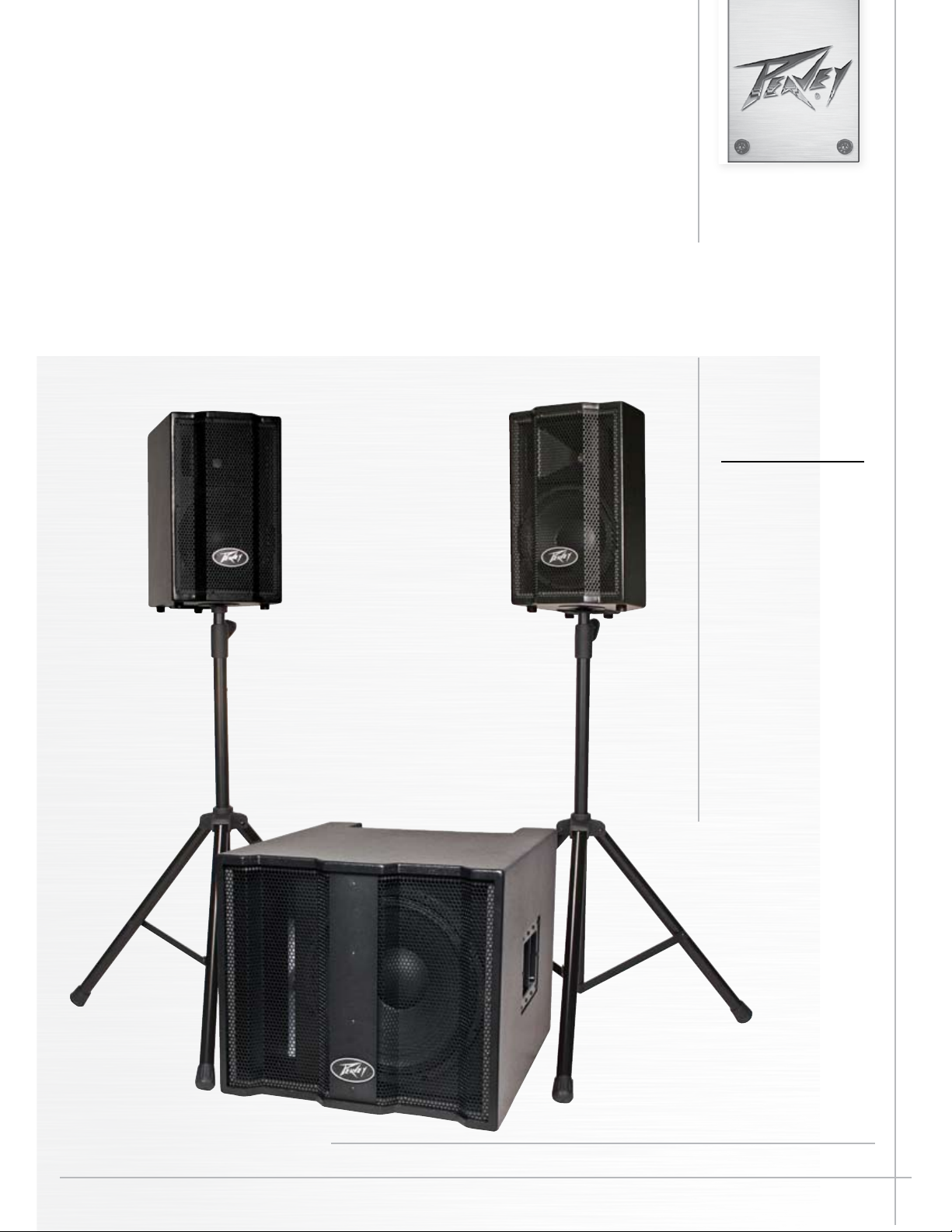
TriFlex™ II
Three-way self-powered two-channel sound
reinforcement system
Operating
Manual
www.peavey.com
Intended to alert the user to the presence of uninsulated “dangerous voltage” within the product’s
enclosure that may be of sufficient magnitude to constitute a risk of electric shock to persons.
Intended to alert the user of the presence of important operating and maintenance (servicing)
instructions in the literature accompanying the product.
CAUTION: Risk of electrical shock — DO NOT OPEN!
CAUTION: To reduce the risk of electric shock, do not remove cover. No user serviceable parts inside.
Refer servicing to qualified service personnel.
WARNING: To prevent electrical shock or fire hazard, this apparatus should not be exposed to rain or
moisture‚ and objects filled with liquids‚ such as vases‚ should not be placed on this apparatus. Before
using this apparatus‚ read the operating guide for further warnings.
Este símbolo tiene el propósito, de alertar al usuario de la presencia de “(voltaje) peligroso” sin
aislamiento dentro de la caja del producto y que puede tener una magnitud suficiente como para
constituir riesgo de descarga eléctrica.
Este símbolo tiene el propósito de alertar al usario de la presencia de instruccones importantes sobre la
operación y mantenimiento en la información que viene con el producto.
PRECAUCION: Riesgo de descarga eléctrica ¡NO ABRIR!
PRECAUCION: Para disminuír el riesgo de descarga eléctrica, no abra la cubierta. No hay piezas útiles
dentro. Deje todo mantenimiento en manos del personal técnico cualificado.
ADVERTENCIA: Para prevenir choque electrico o riesgo de incendios, este aparato no se debe exponer a
la lluvia o a la humedad. Los objetos llenos de liquidos, como los floreros, no se deben colocar encima
de este aparato. Antes de usar este aparato, lea la guia de funcionamiento para otras advertencias.
Ce symbole est utilisé dans ce manuel pour indiquer à l’utilisateur la présence d’une tension dangereuse
pouvant être d’amplitude suffisante pour constituer un risque de choc électrique.
Ce symbole est utilisé dans ce manuel pour indiquer à l’utilisateur qu’il ou qu’elle trouvera d’importantes
instructions concernant l’utilisation et l’entretien de l’appareil dans le paragraphe signalé.
ATTENTION: Risques de choc électrique — NE PAS OUVRIR!
ATTENTION: Afin de réduire le risque de choc électrique, ne pas enlever le couvercle. Il ne se trouve
à l’intérieur aucune pièce pouvant être reparée par l’utilisateur. Confiez I’entretien et la réparation de
l’appareil à un réparateur Peavey agréé.
AVIS: Dans le but de reduire les risques d’incendie ou de decharge electrique, cet appareil ne doit
pas etre expose a la pluie ou a l’humidite et aucun objet rempli de liquide, tel qu’un vase, ne doit
etre pose sur celui-ci. Avant d’utiliser de cet appareil, lisez attentivement le guide fonctionnant pour
avertissements supplémentaires.
Dieses Symbol soll den Anwender vor unisolierten gefährlichen Spannungen innerhalb des Gehäuses
warnen, die von Ausreichender Stärke sind, um einen elektrischen Schlag verursachen zu können.
Dieses Symbol soll den Benutzer auf wichtige Instruktionen in der Bedienungsanleitung aufmerksam
machen, die Handhabung und Wartung des Produkts betreffen.
VORSICHT: Risiko — Elektrischer Schlag! Nicht öffnen!
VORSICHT: Um das Risiko eines elektrischen Schlages zu vermeiden, nicht die Abdeckung enfernen.
Es befinden sich keine Teile darin, die vom Anwender repariert werden könnten. Reparaturen nur von
qualifiziertem Fachpersonal durchführen lassen.
WARNUNG: Um elektrischen Schlag oder Brandgefahr zu verhindern, sollte dieser Apparat nicht
Regen oder Feuchtigkeit ausgesetzt werden und Gegenstände mit Flüssigkeiten gefuellt, wie Vasen,
nicht auf diesen Apparat gesetzt werden. Bevor dieser Apparat verwendet wird, lesen Sie bitte den
Funktionsführer für weitere Warnungen.
IMPORTANT SAFETY INSTRUCTIONS
WARNING: When using electrical products, basic cautions should always be followed, including the following:
1. Read these instructions.
2. Keep these instructions.
3. Heed all warnings.
4. Follow all instructions.
5. Do not use this apparatus near water.
6. Clean only with a dry cloth.
7. Do not block any of the ventilation openings. Install in accordance with manufacturer’s instructions.
8. Do not install near any heat sources such as radiators, heat registers, stoves or other apparatus (including amplifiers) that
produce heat.
9. Do not defeat the safety purpose of the polarized or grounding-type plug. A polarized plug has two blades with one wider than
the other. A grounding type plug has two blades and a third grounding plug. The wide blade or third prong is provided for your
safety. If the provided plug does not fit into your outlet, consult an electrician for replacement of the obsolete outlet.
10. Protect the power cord from being walked on or pinched, particularly at plugs, convenience receptacles, and the point they exit
from the apparatus.
11. Only use attachments/accessories provided by the manufacturer.
12. Use only with a cart, stand, tripod, bracket, or table specified by the manufacturer, or sold with the apparatus. When a cart is
used, use caution when moving the cart/apparatus combination to avoid injury from tip-over.
13. Unplug this apparatus during lightning storms or when unused for long periods of time.
14. Refer all servicing to qualified service personnel. Servicing is required when the apparatus has been damaged in any way, such
as power-supply cord or plug is damaged, liquid has been spilled or objects have fallen into the apparatus, the apparatus has
been exposed to rain or moisture, does not operate normally, or has been dropped.
15. Never break off the ground pin. Write for our free booklet “Shock Hazard and Grounding.” Connect only to a power supply of the
type marked on the unit adjacent to the power supply cord.
16. If this product is to be mounted in an equipment rack, rear support should be provided.
17. Note for UK only: If the colors of the wires in the mains lead of this unit do not correspond with the terminals in your plug‚
proceed as follows:
a) The wire that is colored green and yellow must be connected to the terminal that is marked by the letter E‚ the earth symbol‚
colored green or colored green and yellow.
b) The wire that is colored blue must be connected to the terminal that is marked with the letter N or the color black.
c) The wire that is colored brown must be connected to the terminal that is marked with the letter L or the color red.
18. This electrical apparatus should not be exposed to dripping or splashing and care should be taken not to place objects
containing liquids, such as vases, upon the apparatus.
19. The on/off switch in this unit does not break both sides of the primary mains. Hazardous energy can be present inside the
chassis when the on/off switch is in the off position. The mains plug or appliance coupler is used as the disconnect device, the
disconnect device shall remain readily operable.
20. Exposure to extremely high noise levels may cause a permanent hearing loss. Individuals vary considerably in susceptibility to
noise-induced hearing loss, but nearly everyone will lose some hearing if exposed to sufficiently intense noise for a sufficient
time. The U.S. Government’s Occupational Safety and Health Administration (OSHA) has specified the following permissible
noise level exposures:
Duration Per Day In Hours Sound Level dBA, Slow Response
8 90
6 92
4 95
3 97
2 100
1 1⁄2 102
1 105
1⁄2 110
1⁄4 or less 115
According to OSHA, any exposure in excess of the above permissible limits could result in some hearing loss. Ear plugs or protectors to
the ear canals or over the ears must be worn when operating this amplification system in order to prevent a permanent hearing loss, if
exposure is in excess of the limits as set forth above. To ensure against potentially dangerous exposure to high sound pressure levels, it is
recommended that all persons exposed to equipment capable of producing high sound pressure levels such as this amplification system be
protected by hearing protectors while this unit is in operation.
SAVE THESE INSTRUCTIONS!

ENGLISH
TriFlex™ II
Thank you for purchasing the class D powered TriFlex™ II. The TriFlex II is a three-way self-powered two-channel sound reinforcement system.
Based on a common subwoofer cabinet with a premium 15” woofer, and a pair of two-way satellite speakers with a 10” heavy-duty woofer
and a RX
TriFlex
satellite speaker.
Input jacks provided are a balanced input XLR and a 1/4” phone combo jack, with a pair of RCA phono jacks available, and a Master volume
control and a Sub volume control.
Features
• 1000W Active Two-Channel Three-piece Speaker System
• One shared Subwoofer cabinet which houses the inputs and power amps
• Two two-way Satellite speakers with speaker pole stand adaptors
• Subwoofer has 15” woofer, with 500W peak available power
• Satellite speakers have 10” woofer, RX
• 250W peak available power to each Satellite speaker
• Peavey’s exclusive DDT
• System comes with two 15 foot speaker cables
• Protective slipcover with cable storage pockets and built-in Velcro retaining straps.
• Heavy-duty locking casters on Subwoofer cabinet for transport of system
• Satellite speakers nest on top of the Subwoofer, help ease transport
• Four-pin twist-lock connectors on amplifier outputs and Satellite inputs
™
14 titanium diaphragm dynamic compression driver mounted on a 75° by 75° coverage Quadratic Throat Waveguide™ horn. The
II features a bi-amped power section that provides 500 watts peak power for the subwoofer and 250 watts peak power for each
14 1.4” compression driver tweeter
™
compression on the Satellite power amps.
DESCRIPTION
The TriFlex II is a three piece, two-channel sound system, already tweaked and ready to go for sound reinforcement, DJ gigs, and
various music playback duties. Consisting of a shared Subwoofer cabinet and a pair of Satellite speakers, the TriFlex
pre-engineered for a balanced sound and a crisp, punchy presentation. The three-way effective performance that the system is capable of
provides a clear sound at high output levels, with plenty of punchy bass.
The Subwoofer cabinet has a 15” heavy-duty woofer in it, as well as the system electronics, which consists of a preamp, electronic crossover,
sub-sonic filter, and three power amps. Equipped with 3” heavy-duty locking casters, the Subwoofer cabinet can be rolled around with the
two Satellite speakers nested on top. Once in position, you can remove the Satellite speakers, flip the Subwoofer over 90 degrees onto it’s
rubber feet, and the electronics controls and inputs and outputs are now readily available on the top at the rear of the Subwoofer cabinet.
The sturdy Subwoofer cabinet construction of 18 mm MDF with internal bracing, and a tough black acrylic paint finish, paired with a 16 gauge
perforated metal grille, provide good road-worthiness for years to come.
The amplifier is in a separate sub-enclosure in the Subwoofer cabinet, so the electronics are not exposed to the Subwoofer’s air pressure and
vibration.
Controls and Inputs/Outputs are across the rear top of the unit when it is oriented for use, with the amplifier heatsink on the back panel.
All controls and heatsinks are recessed with no knobs sticking out or sharp heatsink edges exposed.
The Satellite speakers consist of a custom 10” heavy-duty woofer and a Peavey RX14
a Quadratic Throat
waveguide horn. Equipped with a speaker stand pole mount, the Satellite speakers can be placed high up on a speaker
1.4” titanium diaphragm compression driver tweeter on
stand to get the sound out into the audience cleanly. There is also a 45° angled section on the back side of the Satellite speakers so they can
be used as floor monitors when laid on the appropriate side.
Two 15 foot 16 ga. speaker cables with the mating 4-pin twist-lock connectors on each end are supplied with the TriFlex II System to hook-up
the Satellites to the TriFlex
Any good quality 1 3/ 8” diameter pole speaker stands can be used with the TriFlex
speaker stand available as an accessory that will fit into the free slipcover supplied with the TriFlex
II System electronics in the Subwoofer cabinet.
II Satellite speakers, and there is a specific model of
II, the model PP1 speaker stand, Peavey
part number 03011200
II system has been
4
Applications
The Peavey TriFlex™II System has a variety of applications such as DJ, sound reinforcement, public address, or
karaoke. It can even be used as a pair of powered monitors by turning the Subwoofer level all the way down.
A typical signal source for the line-level inputs of the Peavey TriFlex II would be a sound reinforcement mixing
console (mixer) or the output from a CD player, MP3 player or tape deck.
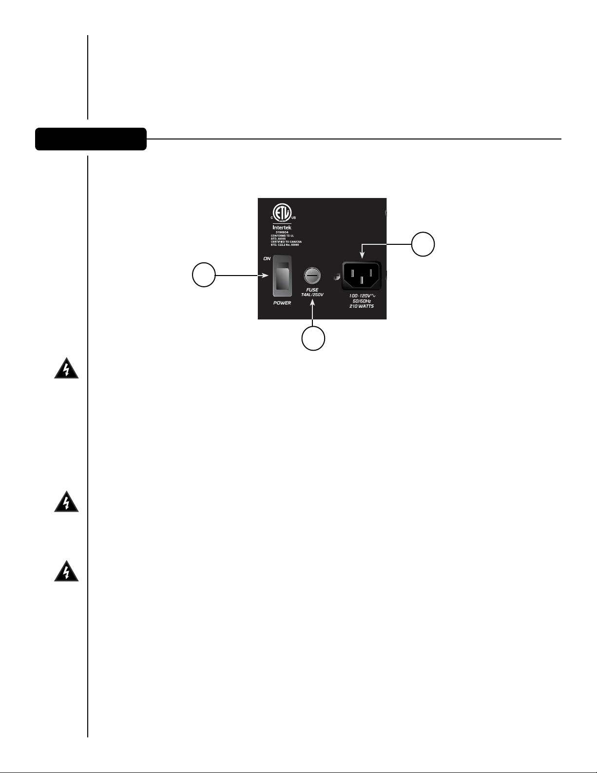
REAR PANEL BOTTOM
2
3
1
FUSE (1)
The unit is AC power line fuse protected from overloads and fault conditions with a slow-blow 4.0 Amp 250V
fuse. This fuse is located within the cap of the fuse enclosure just to the left of the ON-OFF switch. If the
fuse fails, THE FUSE MUST BE REPLACED WITH THE SAME TYPE AND VALUE IN ORDER TO AVOID DAMAGE TO
THE EQUIPMENT AND TO PREVENT VOIDING THE WARRANTY The fuse in the TriFlex II can be replaced with a
time-delay type 5 x 20 mm size, 4 amp 250V rated fuse, which conforms to the international fuse classification
"T4AL". In the USA, types GDC, GMC, 215, 218, and 477 cartridge-style 5 x 20 mm size fuses with a 4 amp 250V
rating can be used. If the unit continues to blow replacement fuses, do not keep replacing them, it should be
taken to a qualified service center for repair.
IEC POWER CORD CONNECTION (2)
This receptacle is for the IEC line cord (supplied) that provides AC power to the unit. It is very important that
you ensure the TriFlex II has the proper AC line voltage supplied. You can find the proper voltage for your TriFlex
II printed next to the IEC line (power) cord on the rear panel of the unit.
Please read this guide carefully to ensure your personal safety as well as the safety of your equipment. Never
break off the ground pin on any equipment. It is provided for your safety. If the outlet used does not have a
ground pin, a suitable grounding adapter should be used and the third wire should be grounded properly. To
prevent the risk of shock or fire hazard, always be sure that the mixer and all other associated equipment are
properly grounded.
ON-OFF SWITCH (3)
This rocker switch supplies AC power to the TriFlex II when switched to the ON position. The ON position is with
the right side of the switch pushed “in” or nearly flush with the rear panel.
5
 Loading...